An Autonomous Landing and Charging System for
Drones
by Ziwen Jiang
B.S., E.E.C.S. M.I.T., 2018
Submitted to the
Department of Electrical Engineering and Computer Science
in Partial Fulfillment of the Requirements for the Degree of
Master of Engineering in Electrical Engineering and Computer Science
at the
Massachusetts Institute of Technology
June 2019
c
○ 2019 Ziwen Jiang. All rights reserved.
The author hereby grants to M.I.T. permission to reproduce and to
distribute publicly paper and electronic copies of this thesis document
in whole and in part in any medium now known or hereafter created.
Author . . . .
Department of Electrical Engineering and Computer Science
May 24, 2019
Certified by . . . .
Hari Balakrishnan
Professor of Electrical Engineering and Computer Science, MIT CSAIL
Thesis Supervisor
May 24, 2019
Accepted by . . . .
Katrina
LaCurts
Chair,
Master of Engineering Thesis Committee
An Autonomous Landing and Charging System for Drones
by
Ziwen Jiang
Submitted to the Department of Electrical Engineering and Computer Science on May 24, 2019, in partial fulfillment of the
requirements for the degree of
Master of Engineering in Electrical Engineering and Computer Science
Abstract
A sensor-equipped consumer-grade drone can help collect data about the world. How-ever, a drone’s flight time today is measured in tens of minutes. Charging multiple drones in a network also requires manual assistance. In this thesis, we develop an integrated system with an autonomous charging pad that a drone can accurately land on. At the same time, the charging system allows the drone to land in environ-ments with low visibility, especially during the nighttime. This research combined vision-based marker detection and flight control algorithms to create accurate landing procedures with different camera modules. Two charging platform designs of wireless and wired contact charging were built with the marker. The autonomous charging system enables a drone to land more accurately than the GPS-based navigation and gets charged without human assistance.
Thesis Supervisor: Hari Balakrishnan
Acknowledgments
I would like to thank all the help and guidance from the Networks and Mobile Systems research group, with whom I was able to develop the drone network and explore interesting engineering topics.
I would also like to thank my family and friends, who supported me throughout my college and M.Eng period.
Contents
1 Introduction 13
2 Related Work 17
3 Drone Model 19
3.1 Hardware Assembly . . . 19
3.2 Onboard Computer System . . . 21
4 Accurate Landing 23 4.1 Infrastructure Overview . . . 23
4.2 Initial GPS Navigation . . . 24
4.3 ArUco Marker Position and Attitude Estimation . . . 25
4.3.1 Camera Calibration . . . 26
4.3.2 Marker Detection and Pose Estimation . . . 29
4.4 Landing Procedures . . . 31
4.4.1 Repetitive Command Control . . . 33
4.4.2 PID Control . . . 34
4.4.3 Multi-level Descending . . . 35
4.5 Night Vision . . . 36
4.5.1 Night Vision Camera . . . 36
4.5.2 Control Method Adjustments . . . 37
5 Drone Charging Platform 39 5.1 Wireless Charging . . . 39
5.1.1 Wireless Charging Coil . . . 40
5.1.2 Charging System Integration . . . 41
5.2 Wired Contact Charging . . . 44
5.2.1 Charging Platform . . . 45
5.2.2 Charging System Integration . . . 45
6 Results 49 6.1 Test Setup . . . 49
6.2 Accurate Landing Tests . . . 52
6.3 Charging Platform Tests . . . 57
6.3.1 Power Analysis . . . 58
6.3.2 Feasibility Analysis . . . 59
7 Conclusion and Future Work 63 7.1 Conclusion . . . 63
7.2 Future Work . . . 64
7.2.1 Accurate Landing . . . 64
7.2.2 Charging Platform . . . 64
List of Figures
3-1 The drone’s hardware setup without propellers. . . 21
4-1 General procedures diagram for accurate landing. . . 25
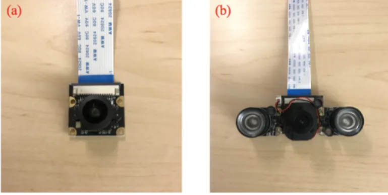
4-2 Camera modules used in the drone network system: (a) wide angle fish-eye camera; (b) automatic IR-Cut sensor vision video camera. . . 26
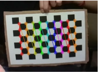
4-3 A Chessboard image with corners detected and drawn by OpenCV functions cv2.findChessboardCorners() and cv2.drawChessboardCorners() for the camera calibration. . . 29
4-4 ArUco marker detected by the wide-angle fisheye camera with marker coordinate system axis drawn in the bright environment [9]. The posi-tion and the attitude of the camera in respect to the marker are shown in the text on the top left side. . . 31
4-5 General procedure diagram for accurate landing control mechanism. . 32
4-6 ArUco marker detected by the night vision camera with marker coor-dinate system axis drawn in the dark environment [9]. The position and the attitude of the camera in respect to the marker are shown in the text on the top left side. . . 37
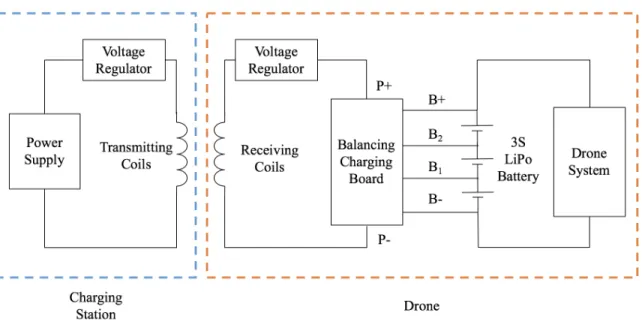
5-1 In this general diagram for wireless charging, the electronic parts of the charging station (left blue box) include a power supply, a voltage regu-lator, and transmitting coils. The electronic parts on the drone (right orange box) include a balancing charging board, a battery, a voltage regulator, and receiving coils. The drone’s battery starts charging when the distance between the transmitting coils and the receiving coils is within the induction length. . . 40 5-2 A wireless charging module with the transmitting coil on top and the
receiving coil at the bottom. . . 41 5-3 The landing platform with the wireless chargers and an ArUco Marker. 42 5-4 A 18650 LiPo battery balancing charging protection PCB. . . 43 5-5 In this general diagram for wired charging, the electronic parts of the
charging station (left blue box) include power supply, a voltage regu-lator, and the copper sheet on the charging platform’s surface. The electronic parts on the drone (right orange box) include a balancing charging board, a battery, and four conductive pads on landing gears. The battery starts charged when the copper sheet on the charging platform and the conductive pads on the drone are in contact. This connection process is similar to a mechanical switch, which is symbol-ized in the diagram (middle green box). . . 44 5-6 The wired contact charging platform with conductive surface and an
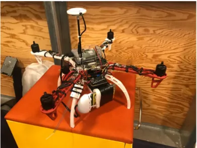
ArUco Marker. . . 46 5-7 (a) Drone with both conductive pads and wireless receiving coils
in-stalled (one of the charging pad at the back side is replaced by wireless charging coils in this figure). (b) A close look at the contact pad in-stalled on the drone. The bottom of the pad is covered with copper tape, while the copper sheet continues to the top of the pad. Wires are soldered on the copper sheet at the top of the pad and connected to the input pins of the balancing charging board. . . 47
6-1 Accurate landing flight tests during (a)the daytime and (b)the night-time. The testing environment during the daytime was not in fully darkness since street light was needed for recording, but the light con-dition was low enough for the necessity of night vision. Flight tests in environment with no street lights were also performed. . . 50
6-2 The camera frame with marker detected and pose estimation on drone with (a) fisheye camera during the daytime; (b) night vision camera during the nighttime. . . 51
6-3 The battery charging measurement setup in the lab for (a) the wireless charging platform and (b) the wired contact charging platform. . . . 51
6-4 The charging board setup with LiPo battery as power supply for wired contact charging and wireless charging platforms at outdoor environ-ment. (a) The drone landed on the the wired contact charging platform at the correct orientation during the daytime. (b) The drone tried to land on wired contact charging platform during the nighttime. (c) The drone landed on the wireless charging platform at the correct orienta-tion during the daytime. (d) The drone tried to land on the wireless charging platform during the nighttime. . . 52
6-5 Average coordinate offsets recorded from marker position estimation at the end of the positioning cycles with wide angle fisheye camera. PID control produced smaller offset than the repetitive control. . . 53
6-6 Average coordinate offsets recorded from marker position estimation at the end of the positioning cycles with night vision camera. PID control produced smaller offset than the repetitive control, while the fisheye camera had better performance than night vision camera on the marker position estimation. . . 54
6-7 Average time spent in each positioning cycle using wide angle fisheye camera and night vision camera. PID control spent less time to position the drone than repetitive control. The time needed for the positioning cycle with the fisheye camera was shorter than that with the night vision camera. . . 55 6-8 Average total time spent in the landing tests using wide-angle fisheye
camera and night vision camera. PID control used a shorter time than the repetitive command control to land the drone. The landing tests with the fisheye camera took less time than the tests with the night vision camera. . . 56 6-9 The final landing locations of the drone with the wide angle fisheye
camera during the daylight using PID control, repetitive command control, and GPS navigation. The landing accuracy of the GPS navi-gation method was the lowest, while the landing accuracy of the PID control method was the highest. . . 57 6-10 The final landing locations of the drone with the night vision camera
during the nighttime using PID control, repetitive command control, and GPS navigation. The landing accuracy of the GPS navigation method was the lowest, while the landing accuracy of the PID control method was the highest. The landing accuracy at night was lower than the accuracy at daytime. . . 58 6-11 Testing results of successful landings for during the daytime and
night-time with wireless and wired contact charging platforms. The wired contact charging platform design had a higher success rate than the wireless charging platform. The landing success rate was higher at the daytime than at night. . . 60
Chapter 1
Introduction
Drones, or unmanned aerial vehicles (UAVs), can fly over a large area and collect data for multiple applications, such as mapping, traffic prediction, environmental monitoring, and early hazard detection [23]. A network that includes multiple drones and schedules different tasks requested by the developers is an excellent example of utilizing a drone’s high flexibility.
However, the drone’s short flight time isn’t able to support it to finish multiple tasks continuously. A drone’s flight time is usually under 30 minutes because of its battery capacity and the weight limit [10]. Drone operator needs to swap the battery manually or connects the drone to a power supply for charging. In a system with multiple drones that covers large areas, such as districts and cities, manual drone charging limits the efficiency of the system and increases the operation cost. We need to develop a method that can charge the drones autonomously within the drone’s coverage area for the sustainability of the system.
In this research, we develop an autonomous charging system for drones. The system is divided into two parts, a landing procedure that allows the drone to land on the target accurately and a charging platform that charges the drone automatically. This thesis will focus on our improved solutions of the landing procedures based on previous methods [13] and exploration of different charging mechanisms.
1. A GPS module for initial charging station allocation.
2. An ArUco marker and drone vision module for position estimation.
3. A drone flight controller and an onboard computer unit for position adjustment.
We experiment two control algorithms, repetitive command control and PID con-trol, to land the done accurately on the target location with the correct orientation and fixed position for autonomous charging outdoors. We also test these control meth-ods with a wide-angle fisheye camera that operates in the daytime and an IR-Cut sensor vision video camera that can operate during both day and night.
The charging station contains an ArUco marker, the charging structure, and a power supply. We explore two charging platform designs, wireless charging using inductive charging coils and wired charging using conductive contacts. The feasibility and power of these two charging platform designs are tested. To be integrated into the drone network, the charging station’s GPS location is also stored in the database of the onboard computer.
With the drone’s position estimated from the marker, our control algorithms can position the drone over the charging platform and accurately land the drone on the platform in multiple tests. Both wireless and wired charging platforms can charge the drone’s battery automatically once the drones lands on the correct position, while they have different charging efficiencies and powers.
The rest of the chapters in this thesis are organized as follows:
∙ Chapter 2 surveys the related work.
∙ Chapter 3 presents an overview of the drone network system and the hardware setup of the drone unit.
∙ Chapter 4 describes the setup and control algorithms we use for accurate land-ing.
∙ Chapter 6 presents the experimental results for accurate landing and charging under different conditions.
Chapter 2
Related Work
Automated drone systems that include landing docks and charging functionality have been explored before [5, 6, 19]. In many precise drone landing projects, the accuracy usually relies on the camera and a visible ground marker. In the research that is done by Zhao and Pei (2012), an improved version of SURF (Speed Up Robust Features) is used to improve the detection of feature points within the landing region [25, 3]. Data from the inertial measurement unit, GPS, and the velocity of the drone are integrated into the calculation of the relative position and orientation of the drone against the ground markers. Another research project uses a convolution neural network (CNN) named, lightDenseYOLO, to infer the marker location [21]. The algorithm combines lightDenseNet as the feature extractor and YOLO v2 as the predictor for one stage de-tection. The system can find the marker direction and relative difference between the centers of UAV and ground markers for position calculation. However, these meth-ods all require heavy-duty onboard computing devices or access to cloud resources, as well as visible light conditions. For autonomous landing with lighter hardware requirement and setup, Junaid et al. (2017) uses a circular target with OpenCV ROS library [13]. They apply image filtering and Hough circle transformation to smoothen the image for object detection. With a flight control algorithm, their quadcopter is able to land on the platform.
For the drone to operate throughout the day and night, the system needs to have lighter hardware setup and the capability of working during nighttime. Xu et
al. (2013) presents an approach using cooperative IR markers on the ground [24]. Their methods utilize the two-step calibration for external and internal parameters, and feature lines of the target to estimate the posture of drones. The conversion between the world coordinate system (WCS) and the camera coordinate system (CCS) determines the rotation matrix that is needed for the position and attitude estimation between the drone and the ground markers.
There are different charging platforms designed for drones. Instead of waiting for the charging to complete on the platform, the charging station developed by Michini, et al. (2011) directly swaps fully charged batteries onto the drone [17]. The landing pad in the station contains sloped edges that help quadcopter slide into the charging position. The grip arms in the front and at the back of the landing pad secure the vertical and horizontal alignment of the drone. The station is also able to charge the batteries that are swapped out and stock them for later usage. Although this charging platform has high efficiency, the complexity of this mechanical landing platform makes the charging station deployment more complicated, especially for the drone system that requires multiple charging stations and operates outdoors. In this case, autonomous charging systems that charge the drone on the platforms have been developed [7, 20]. The charging mechanisms are categorized into two types, wireless charging and wired contact charging. For wireless charging, induction based power transfer circuits are designed especially for drones by different research groups [2, 15]. Both Junaid et al. (2017) and Jung et al. (2012) have developed wireless charging systems using existing inductive coils and voltage regulators for power transmission [13, 14]. Although wireless charging does not require conductive contact, its power efficiency and charging speed may not be optimal for our drones. Wired contact charging has higher power rate. Skysense has presented a wired charging system with electrodes installed on the drone’s battery and a charging pad with conductive surface [1].
In our work, we attempt to combine the techniques from these papers, because they align well with our research goal. We aim to develop an autonomous charging system that can operate at night and charge the battery in a faster way.
Chapter 3
Drone Model
We decide to use Flame Wheel F450 developed by SZ DJI Technology Co., Ltd for the charging system because of its excellent expansion capability, sufficient flight time, and reasonable cost. Compared with other DJI drone models for general consumers, F450 is an industrial model with more flexibility for our customization. Different from other quadcopters, F450 has a higher takeoff weight limit and a larger onboard space. The DJI flight control system and Onboard SDK also help us develop the autonomous charging system faster. In section 3.1, we will present the specific components we use to assemble the drone. In section 3.2, we will introduce the onboard computer setup and the drone control functions we develop.
3.1
Hardware Assembly
The essential drone framework is assembled with an F450 ARF kit and Hobbypower universal tall landing gears (Hobbypower). We install four 420 Lite ESC motors, an N3 flight controller, the DR16 RC receiver system, a GPS module, an onboard computer, an radio, and the power management unit on the drone. The drone’s battery can either be a 3S or 4S LiPo battery with sufficient charge storage since the maximum allowable voltage is 17.4 V.
For communication between the drone and the ground station, we decide to use Nanostation 5AC loco for the radios on the drone and the ground station (Ubiquiti,
US). The Nanostation 5AC loco supports multiple MHz level bandwidth with 13 dBi gain. Its tunable channel selection, sufficient distance, and user-friendly interface are suitable for a quick setup for our experiments.
The drone is powered by a LiPo battery with its voltage regulated. The output of the battery connects to the ESC motors, the drone power management unit, and an additional voltage regulator for the onboard computer, which is a Raspberry Pi 3. The ESC motors require direct connection with the battery that can sustain high current and voltage of at least 11.1 V. The power management unit regulates the power input for DJI drone components, including the N3 flight controller, the GPS module, and the RC receiver. Raspberry Pi 3’s recommended voltage is 5 V, which is regulated by an LM2596 DC-DC buck converter (eBoot). LM2596 DC-DC buck converter is a step-down switching regular that supports up to 7.5 A load current, which is suitable for the onboard computer system on the drone as Raspberry Pi 3’s peak current consumption doesn’t exceed 1 A. For radio powering, since Nanostation requires 24 V power input, we use an XL6009E1 adjustable DC-DC switching boost converter (Sunrom) for stepping up battery voltage to 24 V. Since the regulator can support up to 4 A switching current, and the radio’s power consumption is 8.5 W, the boost converter is sufficient for the system operation. The power is transmitted through the Ethernet power pins on Raspberry Pi 3 from the regulator to radios. Figure 3-1 shows the drone with the hardware setup.
The charging system on the drone supports both wired and wireless charging, which will be explained in Chapter 5. The drone also comes with a remote controller, which is used to manually control the drone and change the flight mode in case of emergency.
Before each experiment, the drone’s IMU and GPS are calibrated for flight safety. The onboard computer is turned on after the calibration finishes. During autonomous landing, the onboard computer controls the drone’s flight locations, as well as com-municating with ground stations for flight status update.
Figure 3-1: The drone’s hardware setup without propellers.
3.2
Onboard Computer System
The onboard computer system is in charge of the flight control during autonomous landing, as well as collecting data and communicating with the ground station.
For the onboard computer system, we decide to use a Raspberry Pi 3 because of its compatibility, cost, and sufficient computation power for our applications. It also supports both Ethernet and wireless communications, which are suitable for our radio setup and onboard electronic components.
Raspbian operating system runs on the Raspberry Pi 3. DJI provides Linux onboard SDK, which contains functions in C++ that allow the drone to takeoff, safely land, and move by a position offset in meters using GPS. Our research group developed a Python library from these flight control functions for our applications. The following functions are used in this research:
∙ Takeoff() takes off the drone and keeps it hovering at a certain altitude.
∙ Landing() slowly lands the drone and turns off the motors.
∙ FlyToXYZYaw(x, y, z, yaw, speed) takes the offsets between the target and the drone’s initial takeoff location on x-, y-, and z-axis of the world’s coordinate system, the yaw angle relative to the North, and the flight speed as inputs. It
outputs flight controller command that flies the drone to the target location and rotates the drone to the target yaw angle with the speed we input.
∙ CurrentYaw() outputs drone’s current yaw angle relative to the North.
Chapter 4
Accurate Landing
For a drone charging system that doesn’t require manual support, it needs to navigate the drone towards the charging station, and control the drone to land on the charging platform at the correct position and orientation. We decide to combine vision-based algorithms and flight control methods to maximize the precision of the drone’s landing location on the charging platform. In this chapter, we will introduce our methods of localizing the charging station and landing the drone during night time. In section 4.1, we will introduce the general landing procedures. In section 4.2, we will present the GPS navigation step that guides the drone to the charging platform. In section 4.3, we will show our methods to detect the ArUco marker and estimation of its position and attitude. In section 4.4, we will illustrate the control methods we implement. In section 4.5, we will discuss the integration of night vision camera into the landing procedures.
4.1
Infrastructure Overview
We use a combination of GPS navigation, ArUco marker localization, and position control to land the drone automatically on the charging platform. In a drone net-working setting, when the drone is low on battery, the onboard computer initiates a charging mission. The onboard computer searches for the closest charging platform’s location and commands the drone to land on the designated station. The locations
of the charging platforms are stored in a static database that the onboard computer can access to.
As shown in figure 4-1, the general procedures of accurate landing have four steps:
1. When the drone initiates the charging task, the onboard computer commands the drone to fly to the target GPS location of the charging station using the GPS module on DJI F450.
2. Because GPS module has certain inaccuracy, the initial navigation towards the charging platform is not precise enough to accurately land the drone on the charging platform. The second step of the accurate landing uses an Aruco marker on the charging platform for the drone with a camera to track platform position. Once the drone detects the location of the ArUco marker relative to the drone, our control algorithm starts positioning the drone to the center above the marker by repetitively adjusting the drone’s location. The position adjustments continue until the drone reaches the center right above the marker or timeout error happens.
3. After finishing the positioning cycle at a certain height, the drone descends to a lower level to repeat another positioning cycle, so that the drone stays above the marker while descending. The errors caused by wind and drifting are minimized.
4. The drone starts the landing process once its location is within the acceptable range of the marker. The onboard computer reports the landing status when drone’s motors are turned off. The autonomous charging process starts after the landing finishes.
4.2
Initial GPS Navigation
GPS navigation is used for the first step of the drone’s accurate landing. We use the FlyToXYZYaw function we create in our Python library from DJI Onboard SDK to
Figure 4-1: General procedures diagram for accurate landing.
command the drone to fly to the location of the charging platform using GPS module. Once the drone reaches the charging platform location, it hovers above the platform and waits for the marker detection in the next step.
4.3
ArUco Marker Position and Attitude Estimation
Detecting ArUco marker and estimating its position and attitude relative to the drone is crucial for localizing charging platform. Matrix barcodes have been widely used in information transfer and marker localization, such as ArUco marker and QR code [22, 12]. ArUco marker comes with great potential for both identification and localization in 3D space [3]. ArUco marker’s black border helps the computer vision algorithm to quickly detect the marker’s location within the image, while the binary matrix inside the border facilitates the ID of the marker. With an ArUco marker embedded in the charging station, the drone can localize the station when it hovers
above the charging platform, and identify whether it lands on the correct platform. Before we use the camera, we need to calibrate the camera to compensate for the distortion caused by pinhole camera structure. During accurate landing procedures, the onboard computer converts camera’s pixel units into real-world units so that the drone can calculate its location relative to the marker’s position in the real-world coordinate system.
4.3.1
Camera Calibration
Camera calibration is necessary to prevent image distortion caused by a pinhole cam-era. We needs to do the calibration for each new camera once before we use it. In our experimental setup, we choose to use two different cameras for tests (figure 4-2). The wide angle fish-eye camera (SainSmart) has a viewing angle of 160 degrees. It supports 1080P resolution at 30 fps and 15-pin MIPI camera serial interface, which is great for integration with the onboard computer Raspberry Pi 3. The other camera we used in our flight experiments is an automatic IR-Cut sensor vision video camera (Dorhea) that supports night vision with a pre-installed IR sensor and IR LED lights. It also supports 1080P resolution with 72-degree viewing angle.
Figure 4-2: Camera modules used in the drone network system: (a) wide angle fish-eye camera; (b) automatic IR-Cut sensor vision video camera.
The wide-angle fish-eye camera was used for most of our tests during the daytime, as it provides broader vision and was convenient for bigger area coverage. The night vision camera was used for the flight test at night since the wide-angle fish-eye cam-era cannot detect the marker in the low light condition. Both camcam-eras are pinhole
cameras, which require camera calibration. To calibration the camera, we measure and calculate the distortion coefficients and the camera matrix.
There are two significant sources of image distortion: radial distortion and tan-gential distortion [3]. Radial distortion causes the straight lines to be more curved when they are further away from the center of the image. Tangential distortion causes the distance between the object and the viewing point to be closer than expected, because of the unparalleled surface between the image plane and the lens plane.
The Brown–Conrady model [4, 8] can correct these two kinds of distortions with the distortion correction formulas. We follow the OpenCV tutorial [18] and calculate the radial distortion and tangential distortion coefficients.
To solve for the radial distortion coefficients, the following formulas are applied:
𝑥𝑐𝑜𝑟𝑟𝑒𝑐𝑡𝑒𝑑 = 𝑥(1 + 𝑘1𝑟2+ 𝑘2𝑟4+ 𝑘3𝑟6) (4.1)
𝑦𝑐𝑜𝑟𝑟𝑒𝑐𝑡𝑒𝑑 = 𝑦(1 + 𝑘1𝑟2+ 𝑘2𝑟4+ 𝑘3𝑟6) (4.2)
in which 𝑟 is the distance between the distorted image point and the distortion center on image plane, 𝑥 and 𝑦 are the distorted image point coordinates, 𝑥𝑐𝑜𝑟𝑟𝑒𝑐𝑡𝑒𝑑 and
𝑦𝑐𝑜𝑟𝑟𝑒𝑐𝑡𝑒𝑑 are the corrected image point coordinates, 𝑘1, 𝑘2, and 𝑘3 are the radial
distortion coefficients.
To solve for the tangential distortion coefficients, the following formulas are ap-plied:
𝑥𝑐𝑜𝑟𝑟𝑒𝑐𝑡𝑒𝑑 = 𝑥 + [2𝑝1𝑥𝑦 + 𝑝2(𝑟2+ 2𝑥2)] (4.3)
𝑥𝑐𝑜𝑟𝑟𝑒𝑐𝑡𝑒𝑑 = 𝑦 + [𝑝1𝑟(𝑟2+ 2𝑦2) + 2𝑝2𝑥𝑦] (4.4)
in which 𝑟 is the distance between the distorted image point and the distortion cen-ter on image plane, 𝑥 and 𝑦 are the distorted image point coordinates, 𝑥𝑐𝑜𝑟𝑟𝑒𝑐𝑡𝑒𝑑 and
𝑦𝑐𝑜𝑟𝑟𝑒𝑐𝑡𝑒𝑑 are the corrected image point coordinates, 𝑝1 and 𝑝2 are the tangential
dis-tortion coefficients.
𝑘1, 𝑘2, 𝑘3, 𝑝1 and 𝑝2 make up the distortion coefficient vector that our camera
In addition to the distortion coefficients, the calibration needs the camera ma-trix for each camera. The camera mama-trix is composed of the intrinsic and extrinsic parameters of the camera, including the focal lengths and the optical center of the camera. These parameters are related to the rotation and translation vectors, which convert images from camera coordinate system to world coordinate system. The camera matrix formula is shown as the following:
⎛ ⎜ ⎜ ⎜ ⎝ 𝑓𝑥 0 𝑐𝑥 0 𝑓𝑦 𝑐𝑦 0 0 1 ⎞ ⎟ ⎟ ⎟ ⎠ (4.5)
in which 𝑓𝑥 and 𝑓𝑦 are focal length, 𝑐𝑥 and 𝑐𝑦 are optical centers.
To obtain the data points needed for the camera calibration, we use a set of known 3D object points from the real-world coordinate system and a set of corresponding 2D image points from images taken by the calibrating camera. As OpenCV has developed functions needed for calibration, including findChessboardCorners(), we decide to use a 7 x 10 chessboard with grid square size of 20 mm as the real-world object for calibration [3, 18].
The calibration procedures are shown as follows:
1. We first take at least 20 images of the chessboard at various angles and locations from a static camera angle, and store them in the JPEG form.
2. We then use the OpenCV function cv2.findChessboardCorners() to find the corners of chessboard images, which are the 2D image points of the chessboard in the camera frame. Figure 4-3 shows a chessboard image with corners detected and drawn.
3. The 3D coordinate points of the chessboard corners are derived from the chess-board grid size and the number of rows and columns. We use cv2.calibrateCamera() with the 3D object points and 2D image points of the chessboard to calculate the camera matrix and the distortion coefficients.
Figure 4-3: A Chessboard image with corners detected and drawn by OpenCV func-tions cv2.findChessboardCorners() and cv2.drawChessboardCorners() for the camera calibration.
With the camera matrix and the distortion coefficients, we can minimize the errors caused by the distortions from the camera lenses.
4.3.2
Marker Detection and Pose Estimation
For ArUco marker detection and pose estimation, we use OpenCV ArUco Marker library [11, 22, 12, 3], and follow the corresponding tutorial [9]. Pose estimation includes the estimation of the marker’s position and attitude relative to the camera. We generate a 160 mm x 160 mm ArUco Marker with ID of 27 from the ArUco marker library’s DICT_4x4_250 dictionary. Once the marker is generated, we put it on the cardboard for a landing platform prototype. For the marker detection, we analyze each image frame captured by the camera and use the OpenCV built-in detection function, detectMarkers(), to detect the marker. The detection procedures are divided into two parts:
1. The image frame is first analyzed by segmentation and thresholding to select the square shaped objects that were marker candidates.
2. Once the marker candidates are selected, the inner codification are extracted by transformation and Otsu thresholding so that we can confirm whether the
marker belongs to the certain library and its specific identifier. Once the de-tection finishes, we obtain the coordinates of the marker’s four corners and its id.
We use the function estimatePoseSingleMarkers from OpenCV to estimate the position and attitude of the marker relative to the camera frame. The function takes the camera matrix, the distortion coefficients, the corners’ coordinates of the marker, and the real size of the marker as input, and outputs the rotation vector and the translation vector that transform points from ArUco marker’s coordinate system to the camera coordinate system. The translation vector contains the marker position relative to the camera. To obtain the attitude of the marker relative to the camera, we use another OpenCV built-in function Rodrigues to convert the rotation vector to the rotation matrix, which contains the roll, pitch, and yaw angle of the marker relative to the camera in marker’s coordinate system. In our landing test design, the scale and orientation of the marker coordinate system is the same as the world coordinate system.
In the real test scenario, the marker is stable on the ground while the camera is moving, so we also calculate the camera position in respect to the marker by multi-plying the transpose of the rotation matrix and the translation matrix. The attitude of the camera regarding the marker can be obtained by multiplying a 180-degree rotation matrix around the z-axis of the camera coordinate system to the rotation matrix. In figure 4-4, an ArUco marker with its position and attitude estimated is shown. Meanwhile, we position the camera at the bottom of the drone and aligned the camera’s coordinate system with the drone’s coordinate system, so that the atti-tude of the camera frame in respect to the marker is also the attiatti-tude of the drone heading direction relative to the marker.
With the drone’s position and attitude relative to the marker on the charging platform figured out, we move on to the control methods of the drone movement that help accurately land it on the charging platform.
Figure 4-4: ArUco marker detected by the wide-angle fisheye camera with marker coordinate system axis drawn in the bright environment [9]. The position and the attitude of the camera in respect to the marker are shown in the text on the top left side.
4.4
Landing Procedures
The landing control algorithm uses the marker’s position on the charging platform as feedback to position the drone so that the drone can hover directly above the center of the marker before landing.
When we need to position the drone above the target marker before landing, the accuracy is affected by the systematic error and environmental conditions, such as wind. To compensate for the interference, we test two control methods: repetitive command control and PID control. We also decide to gradually lower the drone and center it on multiple levels before the final landing.
In figure 4-5, the general block diagram for accurate landing procedures is shown. The accurate landing is initiated by the onboard computer when it detects a low battery condition.
Once the drone hovers above the charging platform at around 2 meters after the initial flight to the charging platform, we start the marker detection and the drone’s position estimation procedures. After we calculate the offsets between the drone’s location and the marker’s location, our flight control algorithms fly the drone to
Figure 4-5: General procedure diagram for accurate landing control mechanism.
the place above the marker. Each positioning cycle takes a certain amount of time because the drone needs to move multiple times to approach the target. At the end of each positioning cycle, we do another round of ArUco marker detection and position estimation to check the relative distance between the drone and the marker. If the distances on both x and y-axis of the world coordinate system are within a certain offset threshold that we set (𝑇1), the drone descends to a lower height. If the distance
on either x or y-axis is above the threshold, we repeat the positioning cycle until either the reserved time for positioning at each height level is over or the relative distance goes below the threshold. A timeout error is recorded if the drone is not able to move to the location within the limit during the positioning process.
We use the FlyToXYZYaw function to position the drone. However, the actual location that the drone flies to have certain offsets compared to the target location due to systematic errors from the flight controller and the GPS module. The offsets are usually within half of meter. The offsets are not significant for the mission that
requires the drone to fly to a general location. However, for accurate landing that requires precise movements on a small scale, the offsets greatly reduce the landing accuracy. This is another main reason that we need to use the control methods during the positioning cycle to compensate for the errors from the FlyToXYZYaw function.
4.4.1
Repetitive Command Control
For repetitive command control, we call the FlyToXYZYaw function with the same input for multiple times during each positioning cycle, and gradually control the drone to approach the target location.
Through experiments, we find that, if we call the FlyToXYZYaw function with the same inputs for multiple times, the ending location of the drone gradually approaches the target location. This phenomenon may be caused by incorrect flight time esti-mation in each flight command, the short movement distance, and the GPS errors. In this case, we design the repetitive command control by calling the FlyToXYZYaw function for a certain amount of times in each positioning cycle. At the beginning of each positioning cycle of repetitive command control, we measure and calculate the offset between the drone and the marker. After that, we use this offset to calculate the target location that the drone needs to fly to based one drone’s current location. The target location is the input of the repetitive command control. The drone flies to a new location after the FlyToXYZYaw function is called. After each FlyToXYZYaw function call, we check the distance between the drone and the marker. If the dif-ference is lower than the threshold (𝑇1), we stop from the current positioning cycle
and proceed to the next step of descending. We also terminate the positioning cycle if the distance between the drone and the marker doesn’t go below 𝑇1 after a certain
amount of the FlyToXYZYaw function calls are finished. After each failed positioning cycle, we reinitialize a new target location based on the updated distance between the drone and the marker.
This method can be quickly implemented, but still can’t avoid the errors from the flight controller system. The offsets between the target location and the end location after theFlyToXYZYaw function call always exist.
4.4.2
PID Control
To better compensate for the error from the flight controller, wind, and the GPS, we develop a PID controller for the positioning cycle that uses the updated distance between the drone and the marker as the feedback to adjust the drone’s position. The PID controller can reduce the constant offsets between the target location and the end location after theFlyToXYZYaw function call.
In this control method, we first set up the target offset between the drone and the marker on the x-y plane of the world coordinate system, which is usually 0, because we want the drone to hover right above the center of the marker. After that, at the beginning of each positioning cycle, we measure and calculate the offset between the drone and the marker. We then use this offset to calculate the target location that the drone needs to fly to. This target location is the initial input into the PID controller, which is stored for the target location update. After each time the FlyToXYZYaw function call is finished, we measure and calculate the updated offset between the drone and the marker. The difference between the current offset and target offset is stored for the PID controller to update the new flight command.
Since the N3 flight controller can separately control movements on x and y direc-tions, we use two PID controllers to calculate the x and y coordinates of the target location needed for the FlyToXYZYaw function separately. The formulas of the PID controller for one coordinate are shown as follows:
𝑐𝑐𝑜𝑚𝑚𝑎𝑛𝑑 = 𝑐𝑐𝑜𝑚𝑚𝑎𝑛𝑑_𝑝𝑟𝑒𝑣+ 𝐾𝑝* 𝑒1+ 𝐾𝑑* 𝑒𝑝𝑟𝑒𝑣+ 𝐾𝑖* 𝑛 ∑︁ 𝑛=1 𝑒𝑖 (4.6) 𝑒1 = 𝑑𝑡𝑎𝑟𝑔𝑒𝑡− 𝑑𝑐𝑢𝑟𝑟𝑒𝑛𝑡 (4.7)
in which 𝑐𝑐𝑜𝑚𝑚𝑎𝑛𝑑 is the updated target location’s coordinate, 𝑐𝑐𝑜𝑚𝑚𝑎𝑛𝑑_𝑝𝑟𝑒𝑣 is the
target location’s coordinate in the previous PID control cycle, 𝑒1 is the difference
between the target offset between the drone and the marker, 𝑑𝑡𝑎𝑟𝑔𝑒𝑡, and the current
offset between the drone and the marker, 𝑑𝑐𝑢𝑟𝑟𝑒𝑛𝑡, 𝑒𝑝𝑟𝑒𝑣 is the difference between the
the previous PID control cycles, 𝑛 is the window size of how many previous errors that we would include in the integral controller; 𝐾𝑝 is the proportional control coefficient,
𝐾𝑑 is the derivative control coefficient, 𝐾𝑖 and is the integral control coefficient.
Through our PID control tests, we tune the PID coefficients, 𝐾𝑝, 𝐾𝑑, and 𝐾𝑖 by
initializing them with the reasonable values related to the sampling rate and adjusting them according to the system performance. We also change the reading window size for integral control based on the consistent error from the proportional control.
The goal of the PID controller is to more accurately position the drone above the center of the marker within a reasonable time.
4.4.3
Multi-level Descending
Multi-level descending allows the drone to land at a low height while keeping the correct position relative to the marker. The drone drifts away from the target during hovering and landing because of wind and other environmental interference. It is important for the drone to start landing at a relatively low height so that wind has less time to interfere with the drone’s location. We decide to gradually lower the drone and readjust its position after each descending movement since the drone’s position shifts even after changing its height.
As shown in figure 4-5, after a successful positioning cycle, the drone descends to a lower height. After each time that drone descends, we first check if the height of the drone relative to the marker is below our landing height threshold (𝑇2) by
marker position estimation. If the drone’s height is still above the threshold, we lower the drone’s height by passing the same x and y coordinates of the drone’s current position, and a lower z coordinates into the FlyToXYZYaw function. The amount of decrements on the z-axis is adjusted in the actual tests. After each height descending step, another cycle of marker position estimation and positioning the drone repeats. Once the drone’s height is below 𝑇2, and the offset between the drone and the marker
is also below 𝑇1, the Landing function is called. The drone slowly lands on the marker.
If the drone doesn’t descend below the threshold within the time limit of the landing process, a timeout error is recorded. The Landing function is called at the end of the
landing process time limit.
4.5
Night Vision
After the implementation of accurate landing with the wide angle fish-eye camera, we also test the night vision camera with an automatic IR-Cut sensor, because the drone system, especially the charging platform, needs to operate during the night.
With the night vision camera module, the drone can detect ArUco marker in a dark environment and performs the same landing procedures introduced in section 4.4. Specific control methods are adjusted to fit the night vision camera.
4.5.1
Night Vision Camera
At night, the regular fish-eye camera isn’t able to detect the ArUco marker, while the night vision camera with high-power IR LEDs and IR sensors can send IR light onto the marker and collects the reflected IR light to detect the marker.
To calibrate the night vision camera, we use the same calibration procedures as the wide-angle fish-eye camera. The camera matrix, the distortion coefficients, the rotation matrix, and the translation matrix are obtained and used for the marker detection and position estimation.
The IR-Cut sensor on the camera automatically removes the IR filter when the visible light is low, so that the camera initiates the night vision mode. The night vision camera can also operate during the day with the IR filter applied. Since our ArUco marker pose estimation functions use grayscale images, the captured images from the night vision camera are converted from RGB format into grayscale format for further processing. The detection accuracy of the ArUco marker by the night vision camera during the day and night is similar. We test the night vision camera during night time in the accurate landing tests.
The ArUco marker detection and position estimation process for the night vision camera is the same as the fisheye camera. The camera’s location relative to the marker is utilized for drone positioning (figure 4-6).
Figure 4-6: ArUco marker detected by the night vision camera with marker coordinate system axis drawn in the dark environment [9]. The position and the attitude of the camera in respect to the marker are shown in the text on the top left side.
4.5.2
Control Method Adjustments
The general flight control methods stay the same for the night vision camera, including multiple cycles of positioning using PID control and repetitive command control and multi-level descending.
However, because the night vision camera has a smaller viewing angle than the wide-angle fisheye camera, the perceiving image frame by the night vision camera covers a smaller area than the fisheye camera. With a smaller coverage area, it is easier for the drone to miss the marker if the positioning movement is too big.
For night vision camera, we change the following parameters in our control meth-ods:
1. We decrease the drone flight speed so that the individual movement steps during positioning cycle is smaller, which prevents the drone from moving out of the marker visible area;
2. We redesign the PID controller and use a smaller proportional control coefficient to reduce the movement size;
Chapter 5
Drone Charging Platform
This chapter discusses the physical design of the charging platform. The platform automatically charges the drone once the drone lands on it. We explore two charg-ing platform designs that can operate without human assistance. The two chargcharg-ing mechanisms are wireless charging and wired contact charging. In section 5.1, we will discuss the wireless charging platform using inductive power transmission coils. In section 5.2, we will present the wired contact charging platform using the conductive metal sheet and pads.
5.1
Wireless Charging
Wireless charging is widely used in the consumer and industrial electronics markets. The convenience and safety of this technology are its main advantages over traditional wired charging that requires conductive metal contact. The wireless charging system contains a charging pad and a power supply. When the drone lands on the charging platform, the platform’s power can sustain the operation of the onboard computer and the flight controller while charging the battery. We decide to use a similar wireless charging system implemented by Junaid et al. (2017) [13] with modification on the charging circuit and the mechanical design to fit the structure of our drone (DJI F450).
The core components of this system are inductive charging coils, voltage regulators, and a 3S LiPo charging balance protection board.
Figure 5-1: In this general diagram for wireless charging, the electronic parts of the charging station (left blue box) include a power supply, a voltage regulator, and transmitting coils. The electronic parts on the drone (right orange box) include a balancing charging board, a battery, a voltage regulator, and receiving coils. The drone’s battery starts charging when the distance between the transmitting coils and the receiving coils is within the induction length.
The transmitting charging coils are connected to the power supply, which can be replaced by other LiPo batteries in an outdoor environment. The LiPo battery on the drone is connected to the balancing charging board. The positive and negative terminals of the battery are connected to the power input pins of the drone system so that the charging current also powers the drone system when the drone lands on the charging platform.
5.1.1
Wireless Charging Coil
For wireless charging module, we use multiple pairs of inductive charging coils for our charging platform implementation. The wireless charging module is composed of transmitting and receiving board and coils (ElecFreaks). For the transmitting side, the control board is built based on XKT-355, a high current low price wireless supply
chip. For the receiving side, the board is built based on XKT 3169, a wireless charging high power receiver chip. The dimensions of the receiving and transmitting coils are of 38 mm diameter with a height of 2 mm. The coil inductance is tuned to be 30 𝜇H (figure 5-2).
Figure 5-2: A wireless charging module with the transmitting coil on top and the receiving coil at the bottom.
For the electrical properties of the wireless charging module, the typical input DC voltage is 12V with limits of 13.5V. The output voltage is regulated to be 12V DC with a maximum output current of 600 mA. The effective inductance distance is 1-20 mm, which is reasonable for our charging system.
5.1.2
Charging System Integration
The base of the charging plate is a 40 cm x 60 cm white acrylic board. On the charging plate, three transmitting coils are placed in a triangle shape on the left side of the ArUco landing marker. The transmitting coils’ location matches the landing gear’s position when the drone lands at the center of the marker and faces to the right. Three transmitting modules are connecting in parallel. They transmit power to the corresponding receiving coils through inductive power transmission.
Three receiving coils are connected in parallel and placed in a triangle shape that matches the transmitting coils on the charging pad. We place the receiving coils at
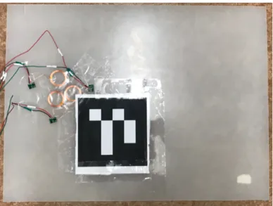
the end of one of the drone’s landing gears so that the charging coils don’t block the camera (figure 5-3).
Figure 5-3: The landing platform with the wireless chargers and an ArUco Marker.
The output of the receiving coils has a DC voltage at around 12V. To step up the output voltage from receiving coils to 12.4V, which is the voltage level of a fully charged 3S LiPo battery pack, we connect the output of receiving coils with the XL6009E1 adjustable DC-DC switching boost converter. The nominal voltage of the 3S LiPo battery is 11.1V, but a higher voltage on the charger side is required for the charging current to flow into the battery.
The output of the boost converter is connected to the power input port of the charging protection board. A 18650 charging protection board has AOD472 transis-tors for charge balancing (figure 5-4) so that each cell within the 3S LiPo battery pack is charged to the same voltage level. Balancing charging is essential for preventing the potential hazard from battery cells with different voltages. B+, B-, B1, and B2 pins are connected to battery’s positive terminal, negative terminal, the battery’s bal-ancing connector’s pins that correspond to the positive terminals of the first and the second battery cell within the battery pack. The maximum operating current and the maximum transient current of the battery protection board are 25A and 40A, which are sufficient for our drone’s charging.
Figure 5-4: A 18650 LiPo battery balancing charging protection PCB.
coils on the charging platform, the drone needs to orient to the correct direction during accurate landing by using the attitude of the drone heading direction relative to the marker.
In our experiment setup, when the drone’s heading position is aligned with the positive y-direction of the marker, the positions of the receiving coils and the trans-mitting coils are matched. At this position, the relative yaw angle between the drone and the marker is 90 degrees.
Before the last landing step of our accurate landing methods, we measure the yaw angle difference between the drone and the marker by marker attitude estimation. Since the function ChangeYaw can rotate the drone to a relative attitude in respect to the North direction, we also measured the current yaw of the drone in regard to the north by calling the CurrentYaw function. By subtracting the yaw difference from the drone’s current yaw and adding 90 degrees, we can calculate the target yaw angle that the drone needs to rotate to.
When the drone lands on the charging platform, the wireless charging module transmits power from power supply to the onboard charging system. The power output from the charging modules is used for sustaining the operation of onboard computer and flight controller, as well as charging the battery.
from the power supply since there is induction charging, while the battery continues to supply power to the drone.
5.2
Wired Contact Charging
We also explore wired contact charging, because the direct connection between a bat-tery charger and a power supply presents a higher power rate and efficiency. Our contact charging platform design also has larger error tolerance for our accurate land-ing methods.
In figure 5-5, a general electronic diagram of the wired contact charging system is shown. The core components of this system are a conductive sheet on the charging platform surface, the conductive pads placed at the end of the drone’s landing gears, voltage regulators, and a 3S LiPo charging balance protection board. The conductive pads are like the electrodes extending from the charging protection board.
Figure 5-5: In this general diagram for wired charging, the electronic parts of the charging station (left blue box) include power supply, a voltage regulator, and the copper sheet on the charging platform’s surface. The electronic parts on the drone (right orange box) include a balancing charging board, a battery, and four conductive pads on landing gears. The battery starts charged when the copper sheet on the charging platform and the conductive pads on the drone are in contact. This con-nection process is similar to a mechanical switch, which is symbolized in the diagram (middle green box).
be replaced by other LiPo batteries in an outdoor environment. A DC-DC voltage converter regulates the output voltage of the charging platform. The specific selection of the voltage converter depends on the power supply rating. Once the drone lands on the charging platform, the conductive surface on the platform and conductive pads on the drone landing gears are in contact to form an electrical path. The power supply is in direct contact with the charging board. Similar to the setup in wireless charging platform, the LiPo battery on the drone is connected to the balancing charging board. The positive and negative terminals of the battery are also connected to the power input pins of the drone system.
5.2.1
Charging Platform
In wired contact charging system, the charging platform is a charging pad with an ArUco Marker placed in the center of the pad. The charging pad is a 40 cm x 60 cm acrylic board, which has good insulation property and durability in an outdoor envi-ronment. The surface of the acrylic board is covered with copper tape for conductive contact. As shown in figure 5-6, a 3 cm gap is left between the top and bottom halves of the conductive surface to avoid shorting the charging circuit. Wires are soldered on the conductive surface of the platform and connect to the power supply. The top half of the conductive pad connects to the positive terminal of the voltage regulator’s output pins, while the bottom half connects to the negative terminal. During idle state, when the drone is not on the platform, no power is consumed from the power supply since the charging circuit is not closed.
5.2.2
Charging System Integration
The charging system on the drone is modified to fit the wired contact charging plat-form. The output of the charging platform is regulated to 12.4V DC so that no additional voltage regulator is needed on the drone. We still use a 18650 charging protection board for balanced charging. B+, B-, B1, and B2 pins on the protection board are connected to battery’s positive terminal, negative terminal and battery are
Figure 5-6: The wired contact charging platform with conductive surface and an ArUco Marker.
balancing connector’s pin, which is the same as the setup in wireless charging. For conductive pads on the drone, we use 3D printed 5 cm x 5 cm pads and installed them on the tips of the landing gears. The front and the back of the con-ductive pads are covered with continuous copper tape. As shown in figure 5-7, two conductive pads are placed on the landing gears of the drone’s front side, which are connected to the P+ pin of the balancing charging board. When the drone lands on the platform, these two pads are in conductive contact with the positive half of the charging platform. The other two conductive pads are placed on the landing gears of the drone’s backside, which are connected to the P- pin of the balancing charging board. During the landing, these two pads are in conductive contact with the negative half of the charging platform.
There are multiple security steps to prevent potential circuit shortage, contact problems, and overcharge. For short circuit and overcharge concerns, the charging protection board itself has an auto-shutdown mechanism when it detects abnormal current and voltage conditions. The charging process also halts when the 3S LiPo battery is fully charged.
To make sure that the conductive pads on drone match the correct terminals of the charging platform, we orient the drone to the correct direction during accurate landing by using the same method we introduce in the wireless charging section.
Figure 5-7: (a) Drone with both conductive pads and wireless receiving coils installed (one of the charging pad at the back side is replaced by wireless charging coils in this figure). (b) A close look at the contact pad installed on the drone. The bottom of the pad is covered with copper tape, while the copper sheet continues to the top of the pad. Wires are soldered on the copper sheet at the top of the pad and connected to the input pins of the balancing charging board.
The attitude of the drone heading direction relative to the marker is measured using marker position estimation.
Different from wireless charging, in the wired contact charging setup, when the drone’s heading direction is aligned with the positive x-direction of the charging plat-form, the charging plates on the drone connect to the correct charging plate halves. The yaw of the drone relative to the marker is around 0 degree. The target yaw angle is calculated by subtracting the yaw difference from the drone’s current yaw.
Firm conductive contact between the conductive pads on the drone and surface of the charging platform is important. We design the surface of both conductive pads and platform to be flat and increase the contact area between the pads and the platform. Once the drone lands on the charging platform, the weight of the drone also helps press the pads onto the platform for more secure contact.
Chapter 6
Results
In this chapter, we will present the results from the landing tests and charging plat-form analysis. In section 6.1, we will describe the general test setup and the param-eters we use. In section 6.2, we will present the results of landing accuracy and time consumption. In section 6.3.1, we will show the power output and the success rate of two charging platform designs.
6.1
Test Setup
The drone’s landing tests were performed in the outdoor environments with the wind speed less than 10 mph for consistency, as shown in figure 6-1. We used an Aruco marker on cardboard instead of the actual charging platform for flexibility, while the marker size and type were the same as the one on the actual charging platform. The flight tests during the daytime were performed with the wide-angle fisheye camera, while the flight tests at night were performed with night vision camera (figure 6-2).
We adjusted the specific parameters needed for our control methods after multiple flight tests. For the offset values during each positioning cycle (𝑇1), we set it to be
15 cm. It means that to finish a positioning cycle successfully, the position of the drone relative to the marker needed to be within 15 cm on both x and y-axis in the world coordinate system. During each cycle of positioning, after marker position estimation through image analysis, it took 0.1 – 0.5 second for the drone to finish
Figure 6-1: Accurate landing flight tests during (a)the daytime and (b)the nighttime. The testing environment during the daytime was not in fully darkness since street light was needed for recording, but the light condition was low enough for the necessity of night vision. Flight tests in environment with no street lights were also performed.
moving. We set the marker position update frequency to be 1.5 Hz. The time limit of each positioning cycle was 10 seconds. If the drone wasn’t able to position itself to an acceptable target location within 10 seconds, the onboard computer reset the target location based on the new relative position of the marker and initialized another positioning cycle. The time limit of positioning at each height level was 30 seconds. For the multi-level descending step in the landing procedures, we set the initial height that the drone hovered over the marker using GPS to be 2.0 m. After each successful cycle of positioning, the drone descended for 50 cm. The landing height (𝑇2) was 1.0
m. If the drone’s altitude was too low, the camera was not able to track the marker since the marker image in the camera frame was too big for the detection method to find the border of the marker.
For the charging power and efficiency measurement, we set up the test bench with a lab power supply and a multimeter for more accurate charging voltage and current measurement (figure 6-3). We used an HRB 3S 11.1V 3000mAh LiPo Battery with
Figure 6-2: The camera frame with marker detected and pose estimation on drone with (a) fisheye camera during the daytime; (b) night vision camera during the night-time.
XT60 connector for both the battery charging tests and the flight tests.
For wireless charging, we set the input voltage for the transmitting coils to be 13 V and maximum allowed input current to be 1.5 A. The permitted maximum charging current for each coil was 0.6 A. With the voltage regulator on the receiving coil side, the actual charging voltage to the battery was regulated to be 12.4 V.
For wired contact charging, we set the charging voltage to be 12.4 V and maximum allowed charging current to be 5 A.
Figure 6-3: The battery charging measurement setup in the lab for (a) the wireless charging platform and (b) the wired contact charging platform.
The feasibility of the charging platform in actual outdoor landing tests was mea-sured with different charging methods, drone hardware setups, and the control meth-ods. The primary purpose of this test was to measure the success rate of initiating the charging process after the drone lands on the charging platform. We wanted to verify whether the charging platform design was feasible in a real outdoor environment.
For the test setup, we placed the charging platform on the surface of either asphalt road or concrete floor. Another Lipo battery with a voltage regulator was used as the power supply source during outdoor tests for both charging platforms (figure 6-4).
Figure 6-4: The charging board setup with LiPo battery as power supply for wired contact charging and wireless charging platforms at outdoor environment. (a) The drone landed on the the wired contact charging platform at the correct orientation during the daytime. (b) The drone tried to land on wired contact charging platform during the nighttime. (c) The drone landed on the wireless charging platform at the correct orientation during the daytime. (d) The drone tried to land on the wireless charging platform during the nighttime.
6.2
Accurate Landing Tests
During the landing tests, we recorded three types of data for comparison among dif-ferent control methods, hardware setups, and environment light conditions as follows:
coordinate system at the end of every positioning cycle.
2. The average time that the drone spent in each positioning cycle and the average total time of the accurate landing tests. The time consumption that drone needs to position itself above the marker is important, as it indicates the efficiency of the accurate landing methods.
3. Landing accuracy. The final landing location of the drone is the determining factor of the success rate of our landing methods. We recorded the x, y co-ordinates of the drone’s landing position relative to the marker in the world coordinate system.
In figure 6-5 and figure 6-6, we present the average offsets on x- and y-axis at the end of positioning cycle for both fisheye camera and night vision camera. The offsets are calculated from the marker position estimation using images taken at the end of the positioning cycles.
Figure 6-5: Average coordinate offsets recorded from marker position estimation at the end of the positioning cycles with wide angle fisheye camera. PID control produced smaller offset than the repetitive control.
Figure 6-6: Average coordinate offsets recorded from marker position estimation at the end of the positioning cycles with night vision camera. PID control produced smaller offset than the repetitive control, while the fisheye camera had better performance than night vision camera on the marker position estimation.
As we can see from the graphs, for both cameras, PID control produced smaller offsets than repetitive control, because the integral control in the PID controller compensated for offsets from the systemic errors. Offsets from the wide-angle fisheye camera are lower than those using night vision camera. The main reason that the night vision camera had larger offsets was that, in some test cases, the drone lost the marker and stayed hovering during the tests until timeout, which was resulted from a smaller camera viewing angle.
These offsets were recorded while the drone was hovering at different height levels. This means that the drone was capable to position itself above the marker on the charging platform. The offsets with the wide-angle fisheye camera are reasonable for the charging platform’s size. The offsets from night vision camera are also close to the acceptable range, while it can be improved with a camera that has a broader viewing angle.
average total time spent for the landing tests (figure 6-8) using the wide-angle fisheye camera and the night vision camera. The most significant improvement of using PID control is decreasing the time needed for each positioning cycle and the whole landing test. As repetitive control gradually positioned the drone to the location above the marker, PID control outputted adaptable target location to reduce the offset between the drone and the marker faster. During the night tests, because we decreased the movement speed and movement size to compensate for the smaller viewing angle of the night vision camera, it took a longer time for the drone to finish each positioning cycle and the whole landing test.
Figure 6-7: Average time spent in each positioning cycle using wide angle fisheye camera and night vision camera. PID control spent less time to position the drone than repetitive control. The time needed for the positioning cycle with the fisheye camera was shorter than that with the night vision camera.
In multiple test cases for repetitive control, the drone lost the marker and stayed hovering. Sometimes, it drifted back to places where it detected the marker again to resume the positioning cycle. However, most of the positioning cycle had timeout errors. The calculated target location was outside of the area where the drone could detect the marker. PID control performed better in this case because it used the

![Figure 4-4: ArUco marker detected by the wide-angle fisheye camera with marker coordinate system axis drawn in the bright environment [9]](https://thumb-eu.123doks.com/thumbv2/123doknet/14136686.469768/31.918.264.655.107.399/figure-aruco-marker-detected-fisheye-camera-coordinate-environment.webp)

![Figure 4-6: ArUco marker detected by the night vision camera with marker coordinate system axis drawn in the dark environment [9]](https://thumb-eu.123doks.com/thumbv2/123doknet/14136686.469768/37.918.267.654.108.398/figure-aruco-marker-detected-vision-camera-coordinate-environment.webp)