HAL Id: hal-00742969
https://hal.archives-ouvertes.fr/hal-00742969
Submitted on 18 Oct 2012
HAL is a multi-disciplinary open access
archive for the deposit and dissemination of
sci-entific research documents, whether they are
pub-lished or not. The documents may come from
teaching and research institutions in France or
abroad, or from public or private research centers.
L’archive ouverte pluridisciplinaire HAL, est
destinée au dépôt et à la diffusion de documents
scientifiques de niveau recherche, publiés ou non,
émanant des établissements d’enseignement et de
recherche français ou étrangers, des laboratoires
publics ou privés.
Boris Kouassi, Irfan Ghauri, Bassem Zayen, Luc Deneire
To cite this version:
Boris Kouassi, Irfan Ghauri, Bassem Zayen, Luc Deneire. On the Performance of Calibration
Tech-niques for Cognitive Radio Systems. Wireless Personal Multimedia Communications (WPMC’11),
Oct 2011, Brest, France. pp.36-40. �hal-00742969�
On the Performance of Calibration Techniques for
Cognitive Radio Systems
Boris Kouassi
1, Irfan Ghauri
2, Bassem Zayen
3, Luc Deneire
11Laboratoire I3S, Sophia Antipolis, France 2Intel Mobile Communications, Sophia Antipolis, France
3EURECOM, Sophia Antipolis, France
Email: kouassi@i3s.unice.fr, irfan.ghauri@intel.com, bassem.zayen@eurecom.fr, deneire@i3s.unice.fr
Abstract—In Cognitive Radio (CR) systems, primary licensed
and secondary unlicensed users share the same spectrum. To minimize the interference caused by secondary users to primary users, we use Beamforming (BF). To perform BF in time division duplex (TDD), we acquire Channel State Information (CSI) with the help of channel reciprocity. This reciprocity is in practice not perfect due to non reciprocal Radio Frequency (RF) front-ends, this non reciprocity can be compensated by calibration algorithms, using only CSI, pilots and signalling. This paper1
compares the performance of three calibration algorithms in OFDM-MIMO (Orthogonal Frequency Division Multiplexing Multiple-Input Multiple-Output) context, namely a M × N SISO and two full MIMO techniques (Alternating Total Least-Squares MIMO: Alt TLS MIMO and TLS MIMO). Simulations performed on synthetic and measured channels show that the TLS MIMO successfully performs full calibration, whereas the less complex SISO method fails to compensate antenna mutual coupling. They also give an approximation of the required CSI to achieve calibration. The final objective is to implement a proper calibration scheme in an existing CR scenario on the EURECOM OpenAirInterface platform.
Index Terms—Cognitive Radio, reciprocity calibration, MIMO/TDD, beamforming, signal processing, channel estimate.
I. INTRODUCTION
Cognitive Radio (CR) is a promising radio communication system that emerged this last decade [1], [2]. It aims to exploit all the radio environment information in order to improve the transmission reliability, whatever the spectrum occupation, the number of users, etc. CR has been classified in three main groups: interweave CR, underlay CR and overlay CR [3]. This paper addresses the interweave CR approach which seeks to use all the available spatial and temporal holes to transmit the cognitive user signals. Thanks to CR, a primary licensed and a secondary unlicensed system can coexist in the same radio environment. The secondary users tempt to access the spectrum without interfering and distorting the primary communication. Therefore, we propose Beamforming (BF) techniques to minimize interference caused to primary users and to maximize the Signal to Noise Ratio (SNR) for secondary cognitive users [4]. To perform BF we exploit
1This work is supported in part by the EU FP7 project CROWN and
SACRA.
the channel reciprocity to derive the Channel State Infor-mation (CSI) allowing to use the locally estimated CSI to compute the beamformer. In practice, the channel reciprocity is destroyed by Radio Frequency (RF) circuits discrepancy. Consequently we need to use RF calibration techniques to restore the channel reciprocity. This paper considers different reciprocity calibration methods in the context of Multi-Input Multi-Output (MIMO) interweave CR network, and evaluate their performance in a real time implementation. The first calibration method consists in subdividing the MIMO channel into M × N SISO channels, hence the name M × N SISO. Then for each SISO channel, the problem is solved by Total Least-Squares (TLS) techniques [5], [6], [7]. Other approaches keep the MIMO structure, and estimate directly the calibration. One derives the parameters thought an alternating TLS method denoted Alternating TLS (Alt TLS MIMO) [8], while the last rewrites the problem in order to solve the calibration issue directly through a TLS solution denoted TLS MIMO [9]. Furthermore, we compare these techniques in terms of the reconstruction performance (both on synthetic and measured channels), and their computational complexity.
An evaluation framework is introduced in this paper to compare the proposed calibration algorithms. Specifically, we developed a real scenario using a Long Term Evolution (LTE) system. This scenario will be implemented on EURECOM’s OpenAir Interface (OAI) platform for real time experiments [10], [11]. The OAI platform is a simulation, emulation and real time experiment platform which tests the validity of innovative concepts in radio networks. We use the CR simulation part to assess the interweave CR implementation. Then, we exploit real channel measurements acquired from EURECOM’s MIMO Openair Sounder (EMOS) to observe the results in a real situation [12]. In order to determine an efficient and real-time processing algorithm, this paper presents the complexity and performance analysis of selected algorithms.
The paper is laid out as follows. Section II presents the system model, the BF scheme and the calibration problem. We explain the techniques to perform reciprocity calibration in Section III. In Section IV we observe and discuss simulation results and computational complexity. Section V addresses the implementation on OAI platform. The conclusions are eventually drawn in Section VI.
II. SYSTEM MODEL PTx STx PRx SRx Primary System Secondary System H22 h11 u1 v1 v2 u2 h12 h21
Fig. 1. Primary and secondary systems
Throughout this paper, we work under the assumption of an Orthogonal Frequency Division Multiplexing (OFDM) system. The model described in Fig.1 is designed assuming a primary system in Time Division Duplex (TDD) mode where users are licensed to communicate in the radio environment unlike the secondary users. However, through spectrum shar-ing, unlicensed users are able to transmit provided they avoid disturbing the primary communication. Our objective is to use interweave CR to meet these constraints while exploiting the primary TDD structure.
In order to perform interweave CR, BF and synchronization scheme are addressed. The secondary transmitter STx steers the signal towards the desired receiver and steers null towards the primary receiver PRx, thus increasing the SNR for sec-ondary receiver SRx and minimizing the interference caused to the primary receiver PRx. The receive interference from secondary to primary users is then expressed by v2hT12 ≈ 0,
where v2 is the BF vector at the secondary transmitter STx.
Furthermore, the transmit (Tx) BF requires the forward CSI between secondary transmitter STx and primary receiver PRx, this information can be obtained by feedback techniques. Unfortunately the primary system has no knowledge of the secondary system, which excludes the possibility to define a feedback procedure.
We propose to exploit channel reciprocity in TDD to obtain the CSI, enabling us to write the forward channel as the transpose of reverse channel and thus derive DL/CSI from UL/CSI and vice versa. As can be observed in the Fig. 2, in a real situation, the reciprocity assumption is jeopardized by RF filters2, estimation error and transmission latency. We
study the distortions generated by RF front ends. To solve the RF impairments and subsequently restore the reciprocity, calibration is required. It consists in finding and mitigating the RF distortion parameters. The literature mainly exposes absolute and relative calibration [8], [13], [14]. The absolute calibration needs a third system to estimate calibration factors, but we are interested by relative calibration (signal-space calibration) which simply uses existent terminals to firstly collect UL and DL CSI, then derive the calibration parameters and finally compensate RF impairments thanks to calibration factors [8].
2Remind that the RF filters models all the processing from signal reception
at the antenna to baseband signal processing.
In the sequel, we present a calibration procedure in the secondary system assuming a M× N MIMO system. Fig. 2 shows the transmission and reception filters TAN ×N, TBM ×M RAN ×N, RBM ×M respectively at front-ends A and B. Without loss of generality, the system model assumes M = N = 2. Given RF filters, one infers (1) and (2).
G= RB.C.TA, H= RA.CT.TB (1) G= PB.HT.PA, (2) PA = R −T A .TA, PB = RB.T −T
B and C is the composite
channel matrix between antennas. It is possible to determine the calibration parameters in SISO, MISO and SIMO as observed in [6].
Considering a SISO system, G= PBHPA= PBPAH, one
observes that PA and PB are scalars, they can be permuted
P = PAPB, G = P H. Thanks to Least-Squares (LS)
meth-ods, we are able to determine the calibration parameters if the system is overdetermined. The solution lies in the possibility to permute the filters for computation.
In SIMO and MISO, only one of the RF filters is scalar, so it is possible to solve the problem, by swapping calibration matrices like: SIMO: GM ×1= PBM ×M.PA1×1.H T M ×1 (3) MISO: G1×N = H1×NT .PB1×1.PAN ×N (4) Tx Tx Rx Tx Rx Rx Tx Rx B A Reciprocity==> Gdl= HTul Gdl Hul c11 c21 c12 c22 C
Fig. 2. Secondary system illustration (2 × 2-MIMO) with RF pairs
One recasts the problem as in SISO, thus it is possible to find a solution using LS methods [7], [5]. In the MIMO case, the equation is:
GM ×N = PBM ×MH
T
M ×NPAN ×N, (5) finding the calibration parameters is less obvious, and we can’t permute the matrices. The following section illustrates the MIMO calibration.
III. CLASSIFICATION OF ALGORITHMS
A. Method 1:M × N SISO
As illustrated in [8], it is possible to solve the MIMO calibration problem considering that each link[i, j](i ∈ M, j ∈ N) is a single SISO channel, we then find the calibration factors as shown in (6).
G(i,j)= PBiH(j,i)PAj = PBiPAjH(j,i) (6)
scalars PAj and PBican be permuted Pji= PAjPBi, G(i,j)=
PjiH(j,i). Thanks to LS methods, we are able to find the
calibration parameters if the system is overdetermined. In practice G and H are estimated with pilots
ˆ
G= G + αG, ˆH = H + αH, (7)
where αGand αH are the estimation errors assumed Gaussian
and i.i.d. The problem corresponds now to a TLS problem [7]. In order to find accurate calibration parameters in noisy channel, we consider K versions of the channel across the time, under the assumption that calibration factors vary slowly in time. Let’s write ˆG and ˆH respectively the DL and UL SISO concatenated channel between the jth antenna at side A and
ith antenna at side B such that ˆG= [ ˆG
(i,j)1, ..., ˆG(i,j)K] and
ˆ
H= [ ˆH(j,i)1, ..., ˆH(j,i)K]. The equation is finally reformulated
as a TLS problem defined by:
argmin
P (|| ˜
H||2+ || ˜G||2) s.t ( ˆH+ ˜H)P = ( ˆG+ ˜G). (8)
With ˜H and ˜G the corrections applied to H and G. The TLS problem can be addressed in different ways [7], [5]. Throughout this paper, we will focus on the Singular Value Decomposition (SVD) solution exposed in [7].
B. Method 2: Alt TLS MIMO
As mentioned earlier, in (5) the inability to permute PAand
PBmakes the problem more difficult. A classical method is to
assume one parameter known (say PA) and estimate the other
(PB). PA and PB are then estimated by an alternating TLS
like illustrated below [8]: 1. Initialize PA= IN
2. Use TLS SVD solution to solve: ˆ
PB s.t arg min ˆ PB
|| ˆPB−1G− HT||
3. Using ˆPB, find ˆPA s.t arg minPˆA|| ˆP
−1
B G− HTPˆA||
4. Iterate from step 2 until convergence
Note that the convergence has not been proved yet.
C. Method 3: TLS MIMO
The last technique consists in rewriting (5) in a new TLS formulation as presented in [9]. Let’s define
P = [vec{PA−1}T vec{PT
B}T]T, (9)
then, we can write the minimization problem as: min
∆E||∆E||F s.t(E + ∆E)P = 0K.N M ×1. (10)
Using K UL/DL channel estimations (k ∈ [1, K]), the system is overdetermined. E= [ET 1, ..., EKT]T ∈ C(KM.N )×(M 2+N2) , (11) and Ek = [Ω − Θ], Θ = IN ⊗ hTk1 .. . IN ⊗ hTkM ,Ω = IM⊗ Gk. (12)
This reformulation permits to directly estimate PA and PB
through a TLS solution. Given E= U ΛVH, the kernel of E
is spanned by the last column (M2+ N2) of V . Consequently,
the SVD solution of (10) is expressed by:
P = − 1
vM2+N2,M2+N2
vM2+N2, (13)
up to a scalar. Using the SVD to solve this special TLS formulation is complex for large matrix E. Fortunately, the system model assumes small size matrix (M, N ≤ 4, and K can be kept small).
IV. SIMULATION RESULTS ANDDISCUSSION
A. Evaluation framework
As mentioned earlier, the system is evaluated assuming a M× N = 2 × 2 MIMO channel (for the secondary link). Two main cases are tested, a channel matrix generated randomly and a real channel matrix measured using EMOS. In the simulated case, the composite channel C∈ CM ×N (Fig. 2.)
and the RF matrices RA,B, TA,B are normally distributed, the
entries of C are drawn from a complex normal distribution CN(µc,Φc2×2), where µc is the mean and Φc =
1 2σ2CI2
the covariance matrix. To reproduce the RF crosstalk effect, diagonal and non diagonal situations are simulated. Assuming a set of Kmaxchannel estimates during the simulation process,
we derive calibration parameters PA,B from K ≤ Kmax
channel estimates.
We finally use algorithms to find calibration parameters P and to reconstruct the channel. The performance evaluation consists in assessing the Mean Square Error (MSE) of the perfect channel G and the channel ˆGrec reconstructed after
reciprocity calibration.
M SE= E(||G − ˆGrec||2F), ˆGrec= G + αGrec (14) To evaluate the accuracy of ˆGrec, a comparison is done with
a maximum likelihood estimator of the mean of ˆG denoted
ˆ
µg = M ×N1 PMi=1
PN
j=1Gˆ(i,j), assuming that the estimation
B. Performance evaluation
The first simulation results given in Fig. 3 and Fig. 4 assesses the performance, assuming no crosstalk between antennas, meaning that PA and PB are diagonal. In order to
evaluate the algorithms reconstruction capability, the compos-ite channel C and RF filters (Fig. 2) are randomly generated.
0 10 20 30 40 10−4 10−2 100 102 104 SNR[dB] MSE MLE TLS MIMO K=3 Alt TLS MIMO K=3 MxN SISO: K=3
Fig. 3. Result with diagonal calibration parameters Kmax= 40, K = 3
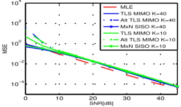
0 10 20 30 40 10−4 10−2 100 102 104 SNR[dB] MSE MLE TLS MIMO K=40 Alt TLS MIMO K=40 MxN SISO K=40 TLS MIMO K=10 Alt TLS MIMO K=10 MxN SISO K=10
Fig. 4. Result with diagonal calibration parameters K = 10, K = 40
As can be observed in Fig. 3 and Fig. 4, K= 3 channel esti-mates provides good performance for M× N SISO unlike Alt TLS MIMO and TLS MIMO. We note generally that K= 10 yields approximately the same results as K = Kmax= 40 in
every cases. Further simulations have shown that K∈ [10 15] allows to determine calibration parameters P accurately. Fig. 5 and Fig. 6 illustrate results with RF crosstalk, modelled by non-diagonal calibration parameters PA,B.
0 10 20 30 40 10−4 10−2 100 102 SNR[dB] MSE MLE TLS MIMO K=3 Alt TLS MIMO K=3 MxN SISO K=3
Fig. 5. Result with non diagonal calibration parameters Kmax=40, K = 3
0 10 20 30 40 10−4 10−2 100 102 104 SNR[dB] MSE MLE TLS MIMO K=40 Alt TLS MIMO K=40 MxN SISO K=40 TLS MIMO K=10 Alt TLS MIMO K=10 MXN SISO K=10
Fig. 6. Result with non diagonal calibration parameters K = 10, K = 40
The M × N SISO performance collapse. Conversely the Alt TLS MIMO and TLS MIMO lead to a better MSE with a slight improvement in the case of TLS MIMO.
C. Computational Complexity
This section derives the algorithmic complexity. Suppose the number of iterations denoted It for Alt TLS MIMO. From SVD computation complexity: O(min(N M2, M N2))
flops [15], we compute the three algorithms complexity: M× N SISO: (1 SVD) O(min(2K2, K22)M N )
Alt TLS MIMO: (2 SVD, It iterations) M in1= min(KM (2N )2,(KM )22N ),
M in2= min(KN (2M )2,(KN )22M ),
O(It(M in1 + M in2)) (15)
TLS MIMO: (1 SVD, 2 Kronecker products, K estimates) M in3= min((KM N )2(N2+ M2), KM N (N2+ M2)2), O(M in3+ K(M2N2+ M3N)) (16) 10 20 30 40 0 0.5 1 1.5 2 x 10⁴ K−Estimates Nb−Operations Complexity MxN SISO TLS MIMO Alt TLS MIMO 10 20 30 40 0 0.01 0.02 0.03 0.04 0.05 0.06 K−Estimates Time[s] Execution Time Alt TLS MIMO TLS MIMO MxN SISO
Fig. 7. Observation of computational complexity and Execution time
Fig. 7 shows the algorithms execution time and complexity variation as functions of K. The execution time is achieved on a computer characterized by: 3GB RAM, CPU Intel P 7450 2, 13GHz. We note that M × N SISO complexity is constant and less restrictive in terms of operations, whereas the Alt TLS MIMO is demanding in terms of calculation, which raises an implementation issue in the OAI platform.
V. IMPLEMENTATION USINGOPENAIRINTERFACE PLATFORM A. Platform Description Parameters Value Center Frequency 1917.6 MHz Bandwidth 4.8 MHz BS transmit Power 30 dBm Number of Antennas at BS 4 Number of Antennas at UE 2 Number of Subcarriers 160 TABLE I EMOS PARAMETERS
The real implementation of calibration techniques will be performed in the OAI. It has been design by the EURECOM Mobile Communication Department, it is a set of development tools composed of radio communication hardware and free software. Three main parts describe the platform: Emulation, Simulation, Real Experiment [10]. The first implementation of calibration will be performed on the CR simulator based on LTE/TDD specifications, to test performances before real time experiments. However, it is important to verify algorithms with real channels. Therefore, real channels acquired with EMOS are used [12].
The sensing procedure is based on a special frame structure Fig. 8. It is composed of SynCHronization symbol (SCH) follows by a Broadcast data CHannel (BCH), and finally 48 pseudo-random orthogonal QPSK signal used as pilots to estimate the channels. This particular frame is designed with 48 pilots to ensure a good SNR and reliable channel estimates. The EMOS characteristics are described in table I, More details are available on the platform website [10], [11].
Fig. 8. EMOS frame structure in OAI OFDM architecture [10].
B. Real channel results
We achieve a Monte Carlo simulation with 500 realisations on real channel measurements. We observe in Fig. 9 the re-construction error between real DL channel estimated through pilots ( ˆG), and the DL channel estimated through reciprocity
( ˆGrec) including UL channel and reciprocity parameters. We
notice after the running of algorithms, that the M× N SISO reconstruction error is better, but still remains larger in general (≥ 10−2). The performance of M× N SISO can be explained
here by the EMOS sensing process without RF crosstalk. VI. CONCLUSIONS
In this paper, we have presented three techniques to per-form reciprocity calibration in a cognitive radio context. The results from simulations show firstly that use K ∈ [10 15] estimates is sufficient to estimate the calibration parameters. Subsequently, we observed that without crosstalk in RF pairs,
0 10 20 30 40 10−2 10−1 100 101 102 SNR [dB] MSE Kmax=50 TLS MIMO K=40 TLS MIMO K=10 Alt TLS MIMO K=40 Alt TLS MIMO K=10 MxN SISO K=40 MxN SISO K=10
Fig. 9. Real channel simulation results
it is better to perform calibration with M× N SISO method which is more efficient and needs less computations. However, considering crosstalk effects, M× N SISO collapsed and we propose to use the TLS MIMO technique which requires more computations, but provides reliable calibration parameters. Eventually, we noted that the M× N SISO algorithm works better for real channel, due to the lack of RF crosstalk in the sensing process. This paper paves the way for a real reciprocity exploitation in MIMO systems and more generally in CR, thus reducing channel estimation and feedback overhead. The next step will consists in evaluating the BF scheme on the experimental platform.
REFERENCES
[1] J. Mitola. Cognitive radio: An integrated agent architecture for software
defined radio. PhD thesis, Royal Inst. Tech. (KTH), Stockholm, 2000. [2] S. Haykin. Cognitive radio: brain-empowered wireless communications.
IEEE Journal, Selected Areas in Communications, 23(2):201–220, 2005. [3] A. Goldsmith, S.A. Jafar, I. Maric, and S. Srinivasa. Breaking spectrum gridlock with cognitive radios: An information theoretic perspective.
Proceedings of the IEEE, 97(5):894–914, 2009.
[4] B.D. Van Veen and K.M. Buckley. Beamforming: A versatile approach to spatial filtering. ASSP Magazine, IEEE, 5(2):4–24, 1988.
[5] N. Mastronardi, P. Lemmerling, and S. Van Huffel. Fast structured total least squares algorithm for solving the basic deconvolution problem.
SIAM Journal on Matrix Analysis and Applications, 22:533, 2000. [6] F. Kaltenberger, H. Jiang, M. Guillaud, and R. Knopp. Relative channel
reciprocity calibration in mimo/tdd systems. In Future Network and
Mobile Summit, 2010, pages 1–10. IEEE.
[7] I. Markovsky and S. Van Huffel. Overview of total least-squares methods. Signal processing, 87(10):2283–2302, 2007.
[8] M. Guillaud, D.T.M. Slock, and R. Knopp. A practical method for wireless channel reciprocity exploitation through relative calibration. 8th
ISSPA 2005, Sydney, Australia, pages 403–406, Aug. 29-Sep. 1,2005. [9] M. Petermann, M. Stefer, D. W ¨ubben, M. Schneider, and K.D.
Kam-meyer. Low-complexity calibration of mutually coupled non-reciprocal multi-antenna OFDM transceivers. In 7th ISWCS, 2010, pages 285–289. [10] Eurecom OpenAirInterface website: http://www.openairinterface.org. [11] K. Florian, G. Rizwan, K. Raymond, A. Hicham, and B. Christian.
Design and implementation of a single-frequency mesh network using openairinterface. EURASIP, 2010.
[12] R. de Lacerda, L.S. Cardoso, R. Knopp, D. Gesbert, and M. Debbah. EMOS platform: real-time capacity estimation of MIMO channels in the UMTS-TDD band. In ISWCS 2007, pages 782–786.
[13] F. Negro, I. Ghauri, and D.T.M. Slock. Transmission techniques and channel estimation for Spatial Interweave TDD Cognitive Radio sys-tems. In 43rd Asilomar Conference on Signals, Systems and Computers, pages 523–527. IEEE, 2010.
[14] A. Bourdoux, B. Come, and N. Khaled. Non-reciprocal transceivers in OFDM/SDMA systems: Impact and mitigation. In RAWCON 2003.
Proceedings, pages 183–186. IEEE, 2003.

![Fig. 8. EMOS frame structure in OAI OFDM architecture [10].](https://thumb-eu.123doks.com/thumbv2/123doknet/13569848.420981/6.918.507.790.85.265/fig-emos-frame-structure-oai-ofdm-architecture.webp)
