ID_ XXX130
CHARACTERIZATION OF MUSSEL SHELLS AS A BIO-BASED BUILDING
INSULATION MATERIAL
Martínez-García, Carolina1; González-Fonteboa, Belén1*; Carro-López, Diego1; Martínez-Abella,
Fernando1; Juan Luis Pérez Ordóñez
1School of Civil Engineering. Department of Construction Technology, University of A Coruña.
Postal Address: E.T.S.I. Caminos, Canales, Puertos. Campus Elviña s/n, 15071 La Coruña, Spain.
*Corresponding author; e-mail: [email protected]
Abstract
In Galicia, 35% of mussel culture is intended for canning. This industry has 25 thousand tons per year of waste (i.e., shells) that mainly ends in landfills or at the bottom of the sea, thereby producing an important environmental impact. After performing a heat treatment, mussel shells become a by-product which is suitable for different uses (poultry feed or bed, soil acidity correction, and fertilizer). However, a minority output and other avenues target related to this by-product must still be explored.
Building insulation materials commonly cause significant harmful effect on the environment, especially if their entire life cycle is analysed (the use of large amounts of energy and water for their production, the difficulty to be recycled, or the reuse of waste in the case of demolition or reform, etc.)
The use of mussels could close the circle of the economy related to the canning industry in Galicia. The aim of this research is to prove the feasibility of mussel shells as a part of building solutions. Suitable thermal and acoustical characteristics of shells as a building insulation material have been found. The confined mussel shell inside a closed space (e.g., in a wooden box) has a thermal transmittance similar to an expanded clay or a light conifer wood, so it can be considered as a material of low thermal conductivity. Moreover, several acoustic studies indicate that a section of confined mussel shell presents a behaviour similar to a double-glazed window. Different building solutions have been designed using shells as a filling insulation material. First, they were tested in a laboratory and then in an experimental building of 60 square meters (Biovalvo Modulus). These modulus mussel shells were used in the roof, the walls and the foundation. Nearly 50 tons of treated mussel shells were converted into a useful by-product which was used as a bio-based building material.
Keywords:
Mussel shell; building insulation, thermal conductivity, sustainability, building acoustics
1 INTRODUCTION
In Galicia, the canning industry has 25 thousand tons per year of waste (i.e., shells) that mainly ends in landfills or at the bottom of the sea, thereby producing an important environmental impact. This waste is only the 35% of the total production of the cultured mussel, and it is heat treated becoming a by-product suitable for different uses (poultry feed or bed, soil acidity correction, and fertilizer). However, a minority output and other avenues target related to this by-product must still be explored.
On the other hand, the building sector is responsible for the 40% of the total energy consumption in Europe, as well as for about 1/3 of greenhouse gas emissions for the whole planet [Asdrubali et al. 2015]. For this reason, the reduction of energy consumption is one of the most important challenges of future buildings. Thermal
insulation is undoubtedly one of the best ways to reduce the energy consumption. The external envelope of a building plays an important role since it strongly affects the surrounding microclimate [Galli et al 2013, Pisello et al.2016]. In the last decades, the development of the envelope has led to an optimal thermal performance of vertical walls in terms of thermal transmittance. Moreover, from the whole energy losses for buildings, there is a large amount of thermal losses through the opaque walls, so using adequately insulated walls has become essential [Schiavoni et al 2016].
Nowadays, building materials are expected to perform several functions as well as to be sustainable. For example, building materials are supposed to satisfy structural, thermal, and acoustical demands [Glé et al. 2011].
The main goal of this paper is to prove the feasibility of mussel shells as a part of building solutions. A thermal
conductivity test was carried out on different mussel shell size particles. One of these sizes was selected to perform a suitable solution to test the airborne sound insulation.
After analysing the results, different building solutions for a roof, walls and foundations were designed. These solutions were constructed and proved in an experimental modulus called Biovalvo Modulus. As a conclusion, mussel shell waste can be used as a by-product with a low energy impact and could be applied for suitable sustainable building solutions.
2 MATERIALS
In the canneries, the mussel (flesh and shell) is boiled in water, eviscerated and mechanically separated from the byssus. What remains of this process is the waste called the whole shell (S) (Fig. 1a). In this project, 25 kg of the whole shell material were characterized and measured. It is mainly composed by shells with one valve or two valves which are joined, broken shells, clamshell bonded to the mussel shell, shells from other molluscs (cockles, oysters, clams, or broken scallops), and a very small part of byssus.
The whole mussel shells have been heat treated at 135 ºC for 32 minutes, using the treatment required by European regulations for poultry feeding as a reference (23). This procedure ensures the disinfection of the aggregates as well as guarantees their safe handling and storage. This treatment resulted in a mussel shell gravel (MG) (Fig.1b). From this mussel gravel, two mussel shell sands were obtained by crushing and sieving: one coarse sand (CMS) (Fig.1c) and one fine sand (FMS), although the latter was not used in this work. Therefore, three different fractions of mussel shell materials have been used in this study (Fig. 1). A total of 75 particles of the whole shell divided into three different series with 2 valves and other three series with 1 valve were measured. The length and width were measured with a digital gauge, and results are shown in Fig. 2. The whole mussel shell length was between 50 and 90 mm, and the width between 20 and 40 mm.
For sizing the characterization of the mussel gravel and coarse, the sand sieve method was used. The mussel gravel had a fineness modulus of 5.38 and a particle size of 4-16 mm. The mussel shell coarse sand had a fineness modulus of 1.90 and a particle size of 0-4mm.
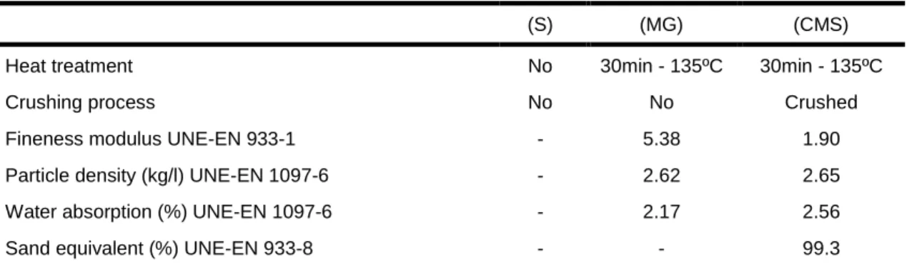
Their particle size distribution is presented in Fig. 3. The main properties of coarse and fine mussel shell materials are shown in Tab. 1.
Fig. 86: Mussel shell used: a) whole shell (S), b) mussel shell gravel (MG), and c) coarse mussel shell
sand (CMS).
Fig. 87: Whole mussel shell (S) size.
Fig. 88: Sieve size distribution of the mussel shell gravel and sand.
Tab. 20: Properties of mussel shell materials.
(S) (MG) (CMS)
Heat treatment No 30min - 135ºC 30min - 135ºC
Crushing process No No Crushed
Fineness modulus UNE-EN 933-1 - 5.38 1.90
Particle density (kg/l) UNE-EN 1097-6 - 2.62 2.65
Water absorption (%) UNE-EN 1097-6 - 2.17 2.56
Sand equivalent (%) UNE-EN 933-8 - - 99.3
0 20 40 60 80 100 120 0 5 10 15 20 25 mm Number of samples
Avg. length 2 valves Avg. width 2 valves Avg. length 1 valve Avg. width 1 valve length2v(s1) length2v(s2) length2v(s3) width2v(s1) width2v(s2) width2v(s3) length1v(s1) length1v(s2) length1v(s3) width1v(s1) width1v(s2) width1v(s3) 0 10 20 30 40 50 60 70 80 90 100 0,0625 0,125 0,25 0,5 1 2 4 8 16 32 Cumu la tiv e pass ing (%) Sieve size (mm) MG (2-16) CMS (1-4)
Flakiness index (%) UNE-EN 933-3 - 99.24 -
Los Angeles Coefficient (%) UNE-EN 1097-2 - 20 -
The mussel shell microstructure was studied in a previous work, providing microscopic images of the different parts of the shells, as it can be seen in Fig. 4. The results of the chemical characterization of materials by XRF are shown in Tab. 2. The main component of the shells in any of the samples is calcium carbonate, approximately 95%. The second compound is silicon oxide, which has a higher quantity in finer samples of mussels. The third component is the presence of sodium oxide which can be related to the presence of sodium chloride in the samples. These results are consistent with those published by various authors studying mussels, oysters, and cockles [Lertwattanaruk et al., 2012; Yang et al., 2005].
Fig. 89: Microstructure of a mussel shell [Martinez-Garcia et al. 2016].
The leaching test was performed according to UNE-EN 12457-4. The quantification of the concentrations of the elements in the leachate was performed by using the high-performance liquid chromatography (HPLC) and the inductively coupled plasma mass spectrometry (ICP-MS). The results of the leaching samples show that whole mussel shells could be classified directly as inert waste. However, mussel shell gravel or sand do not fall within the limits for inert waste. These types of materials comply with the limits for the following non-hazard category, which are 20,000 mg/kg for sulphate and 15,000 mg/kg for chloride. Therefore, samples of CMS and MG would not be under the limit for inert waste, but would be classified as non-hazardous waste.
3 METHODS AND SAMPLE PREPARATION
3.1 Thermal conductivity test
Thermal conductivity λ defines the steady state heat
flow which goes through a unit area of a homogeneous material, 1 m thick, induced by a 1K difference of temperature on its faces. It is expressed in W/m.k. In this work, thermal conductivity was measured according to UNE-EN 12667 for materials with a high thermal resistance. The tests were developed by the Laboratory of Building Quality Control of Vasque Country. The equipment used for the test is a device based on the HFM 436/6/1 Lambda heat flow meter method of the
NETZSCH brand. The control and data acquisition software is Q-Lab 2.
The average temperature of the sample in the test was
10˚C. The average increased temperature between cold
and hot face was 20˚C.
The test had a weight limitation of 25 kg because it is the maximum that the chiller plate on which the material to be tested can resist. The maximum dimensions of the test sample were 60x60x10cm. The measurement was performed on a central surface of the sample of 30x30cm. The tests carried out in accordance with the
aforementioned regulation were made on a
homogeneous material, generally on a plate or a panel. Although the mussel shell is a granular material that was not conform to the regulations, a solution to confine the material was designed in order to fit the test procedure. Three different samples were prepared to analyse the results of this material, with different size distributions and densities.
The specimens were designed to be confined in boxes made of plain laminated plywood board (19 mm), which were fixed with glue and nails. The flatness of both boards (upper and bottom) was maintained to avoid errors in the heat pulse transmission. Five points of heat flow distributed over the surface were applied to each box.
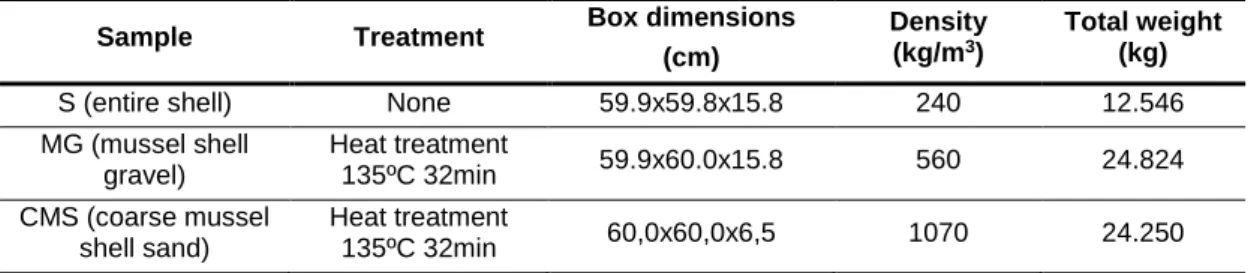
The characteristics of the elaborated boxes with the samples are shown in Tab.3.
The thermal conductivity was calculated as a sum of different parts of the sandwich system designed (upper wooden board + mussel shell + bottom wooden board).
The hot plate (TH) was in contact with the upper wooden
board, and the cold plate (TC) was in contact with the
bottom wooden board (Fig.5).
Fig. 90: Images of the samples: a) entire shell, b) mussel shell gravel, c) coarse mussel shell sand, and
Tab. 21: Description of the samples prepared for the thermal conductivity test.
Sample Treatment Box dimensions
(cm)
Density (kg/m3)
Total weight (kg)
S (entire shell) None 59.9x59.8x15.8 240 12.546
MG (mussel shell gravel) Heat treatment 135ºC 32min 59.9x60.0x15.8 560 24.824 CMS (coarse mussel shell sand) Heat treatment 135ºC 32min 60,0x60,0x6,5 1070 24.250
Thus, the total thermal resistance of the sample tested is the sum of the three resistances that form this thermal circuit. It should be noted that the filling material constitutes a non-homogeneous mixture composed by the random distribution of the shells and the intermediate air cavities.
The value of the filling material (i.e., mussel shell) conductivity was determined by deducting the thermal resistance of each wooden board from the total thermal resistance of the sandwich system.
The thermal resistance provided by the wooden board is determined from its thickness and thermal conductivity by using an equipment according to the ASTM C-1114: 06 standard in which the pair of test t board were of 70x110x7 mm (Fig. 7), obtaining a value
of ʎb = 0.12 ± 0.01 W / m.K.
Fig. 91: The thermal circuit tested which consists of three thermal resistances: two laminated wood boards and the inhomogeneous filling material (mussel shell).
Fig. 92: The wooden boards (70x110x7 mm) tested according to ASTM C-1114:06.
3.2 Sound reduction test
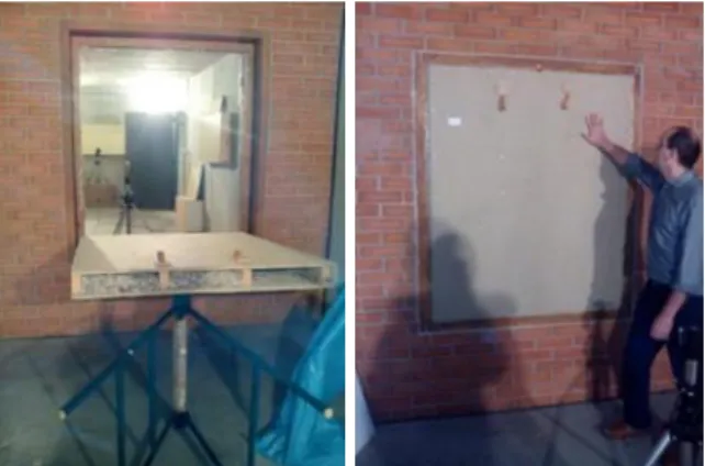
The acoustic test was carried out at the Cortizo Technology Center, concretely in a room equipped for
testing the airborne sound insulation of glazing systems
(Fig. 8). The mussel shell gravel was selected as a filling material in order to design a prototype of an envelope system. This prototype was made of wood boards (OSB) with the MG inside. This was installed in a test bench designed for testing windows.
The designed sample (Fig. 9) was composed by a big
box made of OSB boards, with a density of 650 Kg/m3
and a thickness of 15 mm. The external dimensions of the box were 1490x1240x120mm. Likewise, the box was filled with MG, with an average density of 560
Kg/m3. The thickness of the filling material was 90 mm.
This prototype was installed inside the test bench simulating a window, and it was sealed to the bench with a silicone mastic, which was supplied by the test laboratory. The silicone mastic was dried during 24 hours before performing the test.
The ambient conditions for the text were as follows:
Pressure = 100300±120 Pa
Humidity = 39±10%
Emission room temperature = 18.4±3˚C
Reception room temperature = 18.1±3 ˚C
The test was carried out according to UNE-EN ISO 10140-2. The airborne sound insulation between two rooms with a common horizontal separation was measured. A high enough sound pressure level was generated in one of the rooms, which was called the emitting room, so that it can be received in the other room called the receiving room. The sound detected in the receiving room should exceed at least 15 dB the background noise (ambient noise) of the room. Otherwise, it would be necessary to make the correction determined by the standard.
The acoustic air noise isolation index (Ra) assessed the relationship between the acoustic power incident on the material under testing and the total acoustic power transmitted through the material.
The acoustic noise-to-air noise index RA was calculated
from the sound pressure levels in the emitting room of the sound pressure levels measured in the receiving room. For the calculation, the surface of the sample and the area of equivalent absorption of the receiving room were considered. In addition, such index was calculated from the measured reverberation time values in the
room. The calculation was made according to UNE-EN 717-1.
The overall acoustic reduction index (A) for an exterior
noise (caused by cars) of a building element (RAtr) is the
global assessment of the sound reduction index in dB. Rw is the apparent weighted sound reduction index for automobile exterior noise.
RAtr = RW + Ctr
These parameters are introduced by the standard to take into account the different spectra of the noise sources (such as pink noise or traffic noise) and to evaluate sound insulation curves with very low values in a single frequency band.
The following table includes a guideline on the relevance of such terms according to noise sources. To carry out the test, the following measurement equipment has been used:
Dual channel symphony sound level meter marked 01 dB Metravib model 5470.
Rion brand calibrator with serial number 35173579 model NC-74.
GRAS 40 AF microphone with serial number 77375 GRAS 40 AF microphone with serial number 77374 Computer program dB01.
Dodecahedral speaker.
Volume of the broadcast room. 50.2 m3
Volume of the reception room. 50.5 m3
Fig. 93: Reverberation room.
Fig. 94: The sample designed in the test bench.
Tab. 22: Indicative table on the relevance of the term according the noise sources
Type of noise source
Term for suitable spectral adaptation
Human activities (conversation, music, radio, TV...)
Kids' games
Trains at medium and high speeds Highways more than 80 Km / h.
Jet aircraft at short distances Factories that emit noise of medium
and high frequencies Urban Traffic
C
Trains at low speeds Propulsion aircraft Long-range jet aircraft Music of discotheques Factories that emit noise of medium
and low frequencies
Ctr
4 RESULTS AND DISCUSSION
4.1 Thermal conductivity of mussel shells
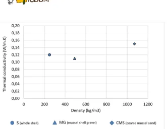
The total thermal conductivity value obtained for the whole shell used as a filling material was 0.12 ±0.01 W/m.K. The total thermal conductivity value obtained for the mussel shell gravel used as a filling material was 0.11±0.01 W/m.K. and the total thermal conductivity value obtained for the mussel shell coarse sand used as a filling material was 0.15±0.01 W/m.K.
Some authors agree that a material is usually considered as a thermal insulator if its conductivity is lower than 0.1 W/m.K. So, it can be said that the mussel shell thermal conductivity value is close to that range. On the other hand, the S and the MG systems density were greater than 300%, and 100% lower than the mussel shell coarse sand density, respectively, but the thermal conductivity measured in the three samples were similar. If the three materials were considered in the same conditions, the average of the three values would have the value of 0.126 ± 0.02, that is, it can be considered as a normal standard deviation.
After analysing the results, it was concluded that the increase in the density of the loose material (mussel shell) had not an important implication in the thermal resistance of the system.
Fig. 95: Thermal conductivity vs density of mussel shells.
Compared with other materials, mussel shells used as a filling material can be considered in the range of thermal conductivity of wood or expanded clay. Moreover, if the mussel shell system is compared with an envelope material (bricks or concrete), it can be said that the former is a better solution from a thermal and environmental point of view.
Materials ʎ (W / m.K). References
Glass wool 0.031-0.037 [Schiavoni et
al 2016]
Cork 0.037-0.042 [Schiavoni et
al 2016]
Expanded clay 0.10-0.14 (Leca®, 2017)
Wood 0.13-0.23 (ICCL, 2017)
Mussel shell 0.11-0.15 This study
Hollow brick 0.32 [ICCL, 2017]
Concrete block 0.45 [ICCL, 2017]
4.2 Acoustic properties
From an acoustic point of view, insulating materials can be characterized in terms of their ability to contrast sound transmission and to absorb impinging sound waves. The sound was dissipated inside a material because of friction or thermal loss (porous materials), as well as because of resonance phenomena (perforated and membrane absorbers) [Schiavoni et al 2016]. Airborne sound insulation is expressed by the weighted sound reduction index Rw, as indicated in UNE-EN 717-1. The sound reduction index defines the ability of a structure (wall, roof, window, etc.) to prevent the passage of sound through itself, and it is expressed in dB [Asdrubali et al. 2015]. Regarding the airborne sound insulation, this characteristic strongly depends on the mass of the materials: lightweight materials are commonly poor sound insulators. On the other hand, the sound insulation of a massive structure mainly depends on the performance of the heaviest components, such as masonry or concrete. If a double wall is concerned, the presence of a sound absorbing material in the gap allows cavity resonances to be limited, and consequently the sound insulation of the wall is increased.
The results measured in the Cortizo laboratories are shown in Tab. 4:
Tab. 23: Results of mussel shell sound reduction test.
Description Value (dB)
Global sound reduction index Rw
(C,Ctr) 42 (-1;-3)
Sound reduction index of airborne
sound RA 41
Sound reduction index of airborne
sound (car noise) RAtr 39
In this project, the building solution tested is not a conventional one from a mass point of view. The OSB
box (650 Kg/m3 each board), with the mussel shell
gravel (560 Kg/m3) inside, was defined with a total mass
solution lower than a conventional one. An example of conventional envelope solution wall could be composed by two walls of ceramic brick, 20 cm the outer brick leaf
and 7 cm the inner brick leaf (770 Kg/m3), with an
insulation material in the gap (<50 Kg/m3) of 3 cm and
with cement coatings in both external sides of the bricks. The former, which was designed for the sound test, had
a weight of 70 Kg/m2, and the latter weighted 280 Kg/m2.
This solution is intended to have an airborne sound reduction of 48 dB [Rindel, 2008].
This aspect, together with the fact that the mussel shell particles were distributed in a chaotic way inside the box with a porous structure, could be the reason for the value obtained in this result.
5 EXPERIMENTAL BUILDING WITH MUSSEL SHELLS AS A FILLING INSULATION MATERIAL
Different building solutions using mussel shells as a filling material were carried out. The aim of this work was the creation of an experimental building called Biovalvo Modulus.
A mussel shell gravel was selected as a filling material for all the building solutions because it had a heat treatment and its thermal conductivity value was the lowest.
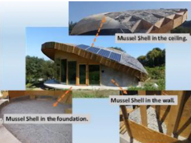
The design had the objective to develop a low energy building according to the Passivhaus standard. In addition, bioconstruction criteria have been applied. The MG was used for the insulation of the whole building without using any other conventional material. In addition, a solution for the foundation was carried out. The mussel shell gravel was used for filling, with a total width of 80 cm. It was compacted into layers. The roof solution was designed with a total of 45 cm of MG filling. Afterwards, it was covered with a wooden board, placing in turn a waterproofing layer on the upper side. The whole shell was selected as the coating for the roof. The vertical envelopes of the building were designed with a total of 45 cm of MG filling, inside a wooden structure closed with wooden board and cement or lime coatings.
0,00 0,02 0,04 0,06 0,08 0,10 0,12 0,14 0,16 0,18 0,20 0 200 400 600 800 1000 1200 Ther m al c ondu ctiv ity (W /m.K) Density (kg/m3)
Fig.11 shows the Biovalvo Modulus with the different mussel shell solutions.
Fig. 11: Biovalvo modulus images. 6 CONCLUSIONS
This experimental study analysed the thermal and acoustic properties of mussel shells, with the aim of proving the feasibility of this waste as a part of building solutions. A mussel shell is a granular, irregular and heterogeneous material, so it is required to be adapted to carry out thermal conductivity and sound reduction tests. As a conclusion, the best way to develop tests is confining the mussel shell in a wooden box.
Three different mussel shell sizes were tested: a whole
shell (240kg/m3), a mussel shell gravel (560 kg/m3), and
a mussel shell coarse sand (1070 kg/m3). The thermal
test showed that the thermal conductivity of the mussel shell was independent on the material density. The average value of the three samples is among the values of thermal behaviour of wood or expanded clay. Furthermore, acoustic characteristics of the shells as a building insulation material have been found. The acoustic studies indicate that a section of confined mussel shell presents similar behaviour to a double-glazed window. Different building solutions have been therefore designed using mussel shells as a filling insulation material.
In this modulus, mussel shells were used in the roof, the walls and the foundation. Nearly 50 tons of treated mussel shells were converted into a useful by-product applied as a bio-based building material.
7 ACKNOWLEDGMENTS
This work has been developed within the framework of the project "Valorización de las conchas de bivalvos gallegos en el ámbito de la construcción" (Valorization of Galician bivalve shell in the construction sector; Code 00064742 / ITC-20133094), funded by CDTI (Centro para el Desarrollo Tecnológico e Industrial) under the FEDER-Innterconecta Program, and co-financed with European Union ERDF funds. We wish to express our most sincere thanks to the professionals of the firms Extraco, Serumano and Galaicontrol.
8 REFERENCES
[Asdrubali et al 2016] Asdrubali, F., Bianchi, F., Cotana, F., D’Alessandro, F., Pertosa, M., Pisello, A.L., Schiavoni, S., 2016. Experimental thermo-acoustic characterization of innovative common reed bio-based panels for building envelope. Build. Environ.
[Asdrubali et al 2015] Asdrubali, F., D’Alessandro, F.,
Schiavoni, S., 2015. A review of unconventional sustainable building insulation materials. Sustain. Mater. Technol. 4, 1–17.
[Galli et al 2013] Galli, G., Vallati, A., Recchiuti, C., de Lieto Vollaro, R., Botta, F., 2013. Passive cooling design options to improve thermal comfort in an Urban District of Rome, under hot summer conditions. Int. J. Eng. Technol. 5, 4495–4500.
[Glé et al 2011] Glé, P., Gourdon, E., Arnaud, L., 2011. Acoustical properties of materials made of vegetable particles with several scales of porosity. Appl. Acoust. 72, 249–259.
[ICCL 2017] ICCL, 2017. CTE WEB [WWW Document]. URL http://cte-web.iccl.es/ (accessed 12.19.18). [Leca 2017] Leca®, 2017. Leca® Lightweight Expanded Clay Aggregate [WWW Document].
[Lertwattanaruk et al 2012] Lertwattanaruk, P., Makul, N., Siripattarapravat, C., 2012. Utilization of ground waste seashells in cement mortars for masonry and plastering. J. Environ. Manage. 111, 133–141. https://doi.org/10.1016/j.jenvman.2012.06.032
[Pisello 2015] Pisello, A.L., 2015. Experimental analysis of cool traditional solar shading systems for residential buildings. Energies 8, 2197–2210.
[Rindel 2008] Rindel, J., 2008. Sound insulation of buildings.
[Schiavoni et al 2016] Schiavoni, S., D׳Alessandro, F., Bianchi, F., Asdrubali, F., 2016. Insulation materials for the building sector: A review and comparative analysis. Renew. Sustain. Energy Rev. 62, 988–1011.
[Yang et al 2005] Yang, E.-I., Yi, S.-T., Leem, Y.-M., 2005. Effect of oyster shell substituted for fine aggregate on concrete characteristics: Part I. Fundamental properties. Cem. Concr. Res. 35.