1
Preparation of Single Crystals
“House-of-Cards”-1
like ZSM-5 and Their Performance in
Ethanol-to-2Hydrocarbons Conversion
3Zhengxing Qin,a Ludovic Pinard,b Mohammed Amine Benghalem,b T. Jean Daou,c Georgian 4
Melinte,d Ovidiu Ersen,d Shunsuke Asahina,e Jean-Pierre Gilson,f Valentin Valtchevf,g* 5
aState Key Laboratory of Heavy Oil Processing, College of Chemical Engineering, China
6
University of Petroleum (East China), Qingdao 266580, China 7
bInstitut de Chimie des Milieux et Matériaux de Poitiers (ICM2P), UMR 7285 CNRS, 4 Rue
8
Michel Brunet, Bâtiment B27, 86073 Poitiers Cedex – France. 9
cUniversité de Haute Alsace (UHA), Université de Strasbourg (UDS), Axe Matériaux à Porosité
10
Contrôlée (MPC), Institut de Science des Matériaux de Mulhouse (IS2M), UMR CNRS 7361, 11
ENSCMu, 3 bis rue Alfred Werner, F-68093 Mulhouse, France 12
dInstitut de Physique et de Chimie de Strasbourg, Université de Strasbourg 23, rue du Loess BP
13
43, F-67034 Strasbourg, France 14
eSEM Application Team, JEOL Ltd., Akisima, Tokyo 196-8558, Japan
15
fNormandie Univ, ENSICAEN, UNICAEN, CNRS, Laboratoire Catalyse et Spectrochimie, 6
16
Boulevard Maréchal Juin, 14050 Caen, France 17
2
g State Key Laboratory of Inorganic Synthesis and Preparative Chemistry, Jilin University,
1
Changchun, 130012, China 2
3
ABSTRACT
1
The present study reports the unbiased chemical etching of micron-sized ZSM-5 crystals with an 2
NH4F solution resulting in house-of-cards-like single crystals containing large rectangular
3
cavities surrounded by thin (15 – 30 nm), flat and highly crystalline walls. The formation of such 4
house-of-cards-like architecture is a result of the preferential extraction of mis-oriented 5
nanocrystalline domains followed by the uniform dissolution of the remaining part of the crystal. 6
The characteristic features of NH4F-treated zeolites are the retention of framework composition
7
(Si/Al) and Brønsted acidity, high crystallinity, a moderate increase in external surface area and 8
increased accessibility to their active sites. Such a combination produces zeolitic catalysts with 9
superior performances (activity, stability and coke resistance) in the ethanol-to-hydrocarbons 10
conversion. The physicochemical properties of this newly engineered zeolite are compared with 11
a hierarchical zeolite obtained by caustic leaching and zeolite nano-sheets synthesized with a 12
bifunctional template, a di-quaternary ammonium-type surfactant. 13
4
1. Introduction
1
Zeolites revolutionized oil refining and petrochemistry due to their excellent chemical and 2
(hydro)thermal stability, unique microporous structures of molecular dimensions and tunable 3
acidity located in a shape-selective environment [1-3]. With an increasing demand for highly 4
active and stable catalysts for existing and emerging processes, recent work with zeolites focused 5
on morphology tailoring either during their synthesis (bottom-up approach) or by post-synthesis 6
modifications (top-down approach), the so-called zeolite crystal engineering [4-8]. 7
Transport limitations in their micropore channels are probably the most serious drawback of 8
zeolite catalysts [9]. Decreasing zeolite crystal size is a straightforward approach to minimize 9
their impact. Advances in the understanding of zeolite nucleation/crystal growth allowed the 10
preparation of nanocrystals of many industrially important zeolites [10, 11]. However, the 11
number of zeolite crystals synthesized with nanosized dimensions is still limited. Zeolite 12
materials with nano-dimensions in a particular crystallographic direction were also prepared 13
[12]. These two-dimensional microporous materials, referred to as layered- or sheet-like zeolites, 14
offer the advantage of extended external surface areas and enhanced diffusion in a particular 15
crystallographic direction. They were prepared, for instance, by Corma and co-workers by 16
exfoliating layered MWW-type zeolite precursors [13]. The exfoliation approach is however 17
limited to a few zeolites since it works with layered precursors with weaker bonds in a particular 18
crystal direction. Ryoo et al. successfully synthesized a series of crystalline molecular sieves 19
(ZSM-5 and zeolite Beta) with tunable mesostructures and nanosheet or nanosponge 20
morphologies using amphiphilic organosilanes or multi-quaternary ammonium surfactants as 21
bifunctional templates [14-16]. A low-cost approach to zeolite nanosheets forming “house-of-22
cards” structures was reported by Tsapatsis et al. [17]. They used a template promoting the 23
5 repetitive branching of orthogonally connected nanosheets. Such intergrowths generate structures 1
with a mesoporous network of 2-7 nm. The resulting polycrystalline hierarchical materials offer 2
the advantages of higher accessibility for bulky molecules, shorter diffusion pathlengths in the 3
microporosity and a larger external surface area. At present such advanced materials were only 4
obtained by a bottom-up approach. To the best of our knowledge, the preparation of house-of-5
cards by a top-down approach has not yet been reported. A post-synthesis approach to house-of-6
cards zeolites would provide significant advantages such as i) applicability to a large number of 7
zeolites; ii) easy transformation of single crystals in house-of-cards materials; iii) cost and 8
environmentally benign scaling-up to produce zeolites. 9
Extraction of framework cations by chemical etching has been used since the first commercial 10
applications of zeolites (eg. hydrocracking, fluid catalytic cracking [FCC], isomerization…) to 11
alleviate these ever-present mass transport limitations. For instance, high-temperature (> 600°C) 12
steaming extracts aluminum from zeolite frameworks and redistributes it in extra-framework 13
positions; while the overall Si/Al is unchanged, the framework Si/Al increases and 14
rearrangement of framework Si generates a secondary mesoporosity [18]. Recently, caustic 15
leaching [19-20] was extensively revisited, better understood and shown to generate secondary 16
mesopores in high silica zeolites [21]. Chemical etching is an efficient and straightforward 17
method to improve intra-crystalline transport and reduce diffusion barriers. However, the 18
preferential or biased extraction of a particular framework cation (Al or Si) leads to a dissolution 19
profile, strongly dependent on the zeolite composition and therefore difficult to control. 20
Recently, an unbiased chemical etching was developed using NH4F solutions [22-26].
21
Concentrated ammonium fluoride solutions were shown to dissolve Si and Al from zeolite 22
frameworks at equal rates. While leaving the zeolite composition (Si/Al) unchanged, this 23
6 approach dissolves preferentially defects in zeolite crystals, such as interfaces between twin 1
crystals, grain boundaries, lattice defects… This unbiased fluoride extraction is HF-free; 2
moreover, the biased (NH4)2SiF6 processing of zeolites is currently used in the commercial
3
production of modified (dealumination and subsequent healing by silication) FAU zeolites (LZ-4
210 from UOP LLC. [27-28]) 5
The objective of the present work is to develop a universal top-down approach to produce 6
single crystals house-of-cards-like zeolite catalysts. It is based on the recently discovered mosaic 7
structure of zeolite crystals, i.e., the presence of rectangular nanocrystalline domains with well-8
defined grain boundaries [24]. Such domains were observed in MFI [24], FER [29], FAU [30], 9
and appear to be ubiquitous. They are preferentially dissolved when an unbiased chemical 10
etching is applied to zeolite crystals, leaving behind rectangular cavities several tens of 11
nanometers wide. The remaining part of the crystals dissolves with a similar rate of dissolution 12
following the morphology of extracted nanocrystalline domains, which is employed in the 13
present study to form a house-of-cards-like material by post-synthesis etching. This is illustrated 14
by comparing the unbiased NH4F etching of a parent (ZP) ZSM-5 zeolite, ZF, a Si biased caustic
15
leaching of the same parent, ZB [31], and zeolite nano-sheets (ZNS) prepared with a di-quaternary
16
ammonium-type surfactant acting as a bifunctional structure directing agent [32]. The Ethanol-17
to-hydrocarbons (ETH) conversion was used as a model reaction to evaluate the catalytic 18
potential of these zeolites and relate it to their physicochemical properties. 19
2. Results and discussion
20
2.1 Physicochemical characteristics of the zeolites
21
2.1.1 XRD
7 The samples preparation is provided in the supporting information. The XRD patterns of ZP
1
(commercially available zeolite ZSM-5, the parent), ZB (a biased caustic etching of ZP), ZF (an
2
unbiased NH4F etched derivative), and ZNS (a bottom-up ZSM-5 nanosheets preparation)are
3
displayed in Figure 1. ZP shows sharp and narrow peaks characteristic of a highly crystalline
4
micron-sized MFI-type material. The XRD peaks of ZF are equally narrow and well-defined,
5
indicating that the NH4F etching does not impact crystallinity. ZB shows much lower peak
6
intensities than its parent. Some of the peaks are missing in the XRD pattern of ZNS, as expected
7
for such type of material [32]. 8 9 10 11 12 13 14
Figure 1 The XRD patterns of the parent zeolite (ZP), its NH4F (ZF) and caustic (ZB) etched
15
derivatives, and a nano-sheet zeolite (ZNS).
16
2.1.2 N2 Physisorption
17
The physicochemical properties of all zeolites are summarized in Table 1. The parent micron-18
sized (ZP) crystals display a type I isotherm (Figure S1) characteristic of a purely microporous
19
zeolite [33]. ZF and ZB zeolites exhibit a second uptake and a hysteresis loop at high relative
8 pressure revealing the presence of mesopores. The micropore volume of ZF is fully retained
1
compared to its parent and its external surface area is lower than its caustic leached counterpart, 2
ZB; ZB has however lost some of its micropore volume, in agreement with the XRD data. The
3
zeolite nano-sheets, ZNS, display a Type I isotherm at low p/p0 combined with a type IV(a) at
4
high p/p0. The presence of a hysteresis loop in the relative pressure range 0.4 < p/p0 < 1 is typical 5
for such lamellar materials due to the stacking of nanosheets. ZNS also exhibits a lower
6
micropore volume and larger external surface area. The mesopores distribution for all samples is 7
presented in Figure 2. No mesopores are observed in the parent micron-sized crystals, ZP. ZF
8
exhibits a large pore size distribution between ca 10 nm and more than 100 nm. The ZB pore size
9
distribution is also large, but within the mesopore range, i.e., 2 to 50 nm [33]. The pore size 10
distribution of ZNS, with a maximum of around 6 nm, is much sharper compared with ZB and ZF.
11
All three hierarchical zeolites have a mesopore volume higher than 0.3 cm3 g-1 (Table 1).
12
However, ZF shows only a slight increase in external surface area compared to its parent.
13
Conversely, ZB and ZNS bothdevelop external surfaces exceeding 200 m2 g-1. We attribute these
14
differences to the types of pores formed by NH4F and caustic leaching and the stacking of
15
nanosheets, respectively. The dissolution in fluoride medium results in the formation of large 16
meso- and macropores (Figure 2), which exhibit low specific surface area (Table 1). This can be 17
further interpreted based on a rough estimation of the relation between the surface (S), the pore 18
diameter (d) and the pore volume (V) using d = 4V/S. In contrast, both ZB and ZNS contain a
19
substantial amount of small mesopores with size below 10 nm (Figure 2). Accordingly, a 20
substantial increase in the external surface area is observed (Table 1). 21
22 23
9
Table 1. Physicochemical characteristics of the series of ZSM-5 samples.
1 2
Samples Si/Ala
SBETb Sextc Vmicc Vmesod BPye LPye
m2 g-1 m2 g-1 cm3 g-1 cm3 g-1 µmol g-1 µmol g-1
ZP 21 377 9 0.18 0.02 617 91
ZF 22 395 54 0.17 0.31 582 51
ZB 9 494 206 0.13 0.36 495 282
ZNS 37 504 266 0.11 0.40 162 98
aICP. bBET surface area. ct-plot. d V
meso = Vtotal – Vmic (Vtotal: the volume absorbed at p/p0 =
3
0.99). eThe Brønsted (BPy) and Lewis (LPy) acidity were determined by IR analysis of pyridine
4
sorption. 5
6
Figure 2. BJH pore size distribution of the parent zeolite (ZP), its NH4F (ZF) and caustic (ZB)
7
etched derivatives and the nano-sheet zeolite (ZNS).
8
2.1.3 Morphological analysis
10 The morphology and secondary porosity of the zeolites are described by combining scanning 1
(SEM) and transmission electron microscopy (TEM). NH4F etching transforms the micron-sized
2
ZSM-5 crystals (Figure 3a, insert) into a foam-like material with thin crystalline walls (Figure 3
3a, b). The macro-morphological features of the crystals are retained. However, the crystalline 4
body is fully transformed into a mosaic of rectangular cavities, large enough to be observed with 5
a scanning electron microscope (Figure 3a, b). TEM provides further insights into the structure 6
and morphology of the NH4F etched zeolite. Figure 3c shows a representative TEM image of
7
such an NH4F etched ZSM-5 crystal. Figure 3e-g show slices through the electron tomography
8
reconstruction of a selected zeolite grain. The slices highlight the high porosity of chemically 9
treated zeolite but also the remained crystalline pore walls (Figure 3d) with a thickness ranging 10
from 10 to 30 nm. The tomography shows that the NH4F etched zeolite contains two types of
11
secondary pores: i) large interconnected rectangular-shaped, ii) smaller ones probably formed 12
later on during the etching. 3D models indicate that even the vast majority of the smaller 13
mesopores are connected to the secondary porous network, indicating that pore connectivity 14
approaches 100 % and an overall meso-macroporosity of around 47%. This excellent 15
connectivity between the various pore networks is an important, albeit often overlooked, feature 16
in hierarchical zeolites [34]. The porosity could even be higher as some of the surface pores 17
(Figure S2) were excluded from the quantification. The 3D geometry of the porous network and 18
their walls resemble the “house-of-cards” architecture. A schematic presentation of the 19
remaining part of the crystals with the vast sytem of rectangular, interconnected cavities is 20
presented in Figure S3. It is remarkable that such a significant secondary porosity increase in ZF
21
is achieved without loss of intrinsic microporosity and acidity (Table 1) as well as crystallinity 22
(Figure 1, Figure 3d). 23
11 1
Figure 3. Low (a) and high (b) resolution SEM images of ZF sample. Representative low (c) and
2
high (d) resolution TEM images of ZF. TEM tomography slices in zx direction (e, f, g).
3
4
Zeolite dissolution process is strongly influenced by the zeolite framework composition and 5
crystal zoning in the case of selective chemical extraction of a framework cation [35–37]. The 6
NH4F did not show any sensibility to the framework ratio, including in the case of very low silica
12 zeolites [25, 26]. Indeed the ZF sample shows a Si/Al ratio very similar to its parent (Table 1).
1
For this reason, we consider that the exceptional resistance of the periferic parts of the crystals to 2
the NH4F etching (Figure 3a, Figure S4, S5) is an important observation. In order to get a deeper
3
insight into this peculiar “selected-area” dissolution behavior, a comparative study was 4
conducted by combined use of high and low voltage SEM. The electron beam penetrates deep 5
into the sample at high accelerating voltage. Accordingly, the signal will carry information from 6
deeper layers of the sample. In contrast, low voltage high resolution SEM provides only the 7
surface information thanks to the much lower landing voltage [38]. Therefore, as the intensity of 8
the generated secondary electrons varies depending on the magnitude of the accelerating voltage, 9
variations in the roughness of specimen surface and the density of the substance can be detected. 10
As can be seen in Figure S6, the crystal surface of ZP shows a uniform contrast under both high
11
and low voltage observation models. The 5 min NH4F-treated sample also shows a uniform
12
contrast under the low voltage observation model (Figure S7a). In the case of the high voltage 13
model, however, obvious dark areas occur on the b crystal face of the NH4F-treated sample
14
(Figure S7b). This contrast difference is not related to crystal surface etching (i.e. surface 15
roughness), since only a few seperated holes can be observed on the b crystal face (Figure S8e). 16
This crystal surface still shows a similar smouth morphology as the untreated sample, with the 17
growth steps clearly distinguishable (Figure S8b, e). In addition, the difference in surface 18
contrast is not an individual but a general phenomenon, as a similar inhomegeneous distribution 19
of the phase contrast was also observed in case of the 10 and 20 min NH4F-treated samples
20
(Figure S9). The surface contrast is not so different in the case of the longer time (i.e. 30 and 60 21
min) treated samples (Figure S10). In the later case the original crystal surface are either deeply 22
13 etched, or detached as a result of the substantial dissolution of the inner part of zeolite crystals 1
(Figure S11). 2
Based on these intensive SEM observations, we attribute the difference in surface contrast to 3
the difference in density in different parts of zeolite crystals. Namely, the dissolution of zeolite 4
crystals in NH4F solution is spacially inhomogeneous in the macro sense. In general, the inner
5
part of zeolite crystals are preferentially dissolved. The gravimetric measurement of the weight 6
loss of zeolite with the extension of NH4F etching was also conducted (Figure S12). The
7
continuous decrease of the slop of the weight loss curve shows unambiguously that the 8
dissolution of the ZP crystals is relatively faster at the initial stage and the dissolution rate slows
9
down with increasing etching time (Figure S12). We further attribute the faster dissolution of the 10
inner part to the fast growth rate at the early stage of crystal growth, and the slower dissolution 11
of the crystal periphery to the slow growth rate at the end of the crystallization process where a 12
few defects are formed. Thus the defect-poor parts of the crystals are resistant to the etching. 13
This result is additional evidence showing that the dissolution starts preferentially from 14
framework defects when unbiased etching solution is used. 15
The relation between the crystallographic structure of the zeolite crystals and the etching 16
direction shown in Figure S4 is confirmed by the high-resolution analysis of some similar grains. 17
Figure S13 shows a typical high-resolution TEM image and the corresponding FFT pattern 18
which illustrate that the preferentially etched facets are on {010} face, as revealed also by the 19
low-magnification TEM images of the various analyzed zeolite crystals. It should be underlined 20
that the empty cages resulting from the crystal dissolution are orianted along the crystallographic 21
axes. This is a proof for the connection between the growing process and dissolution behaviour 22
14 of the crystals. The high-resolution image shown in Figure S14 also sustains this important 1
finding. 2
We attribute both the spacially inhomegeneous dissolution and the facet-dependent etching 3
behavior to the growth mechanism. The fluoride etching is sensitive solely to the zones of 4
structural stress and deffect concentartion (Figure S8d) which are more vulnerable to chemical 5
attack [24, 39, 40]. Thus the dissolution reflects the particularities of the growth process. Layer 6
type growth is characteristic of most of the zeolitic materials [41–44]. The detailed mechanism 7
of MFI growth was revealed recently by in situ AFM microscopy [43]. It was observed that the 8
MFI growth involves two simultaneous phenomenon - oriented attachment of nanoparticle and 9
mono- or low-weight silica species. The nanodomains integrated into the growing crystal contain 10
well defined grain boundaries and thus are rapidly disolved by NH4F etching (Figure S8c, f),
11
leaving behind rectangular cages [24]. These rectangular cages are surrounded by crystalline 12
material, which is a result of the uniform growth by means of low weight silica species. The rate 13
of dissolution of this more stable and uniform part of the crystal is lower (Figure S12). Judging 14
by the straight and flat crystalline walls surrounding the cages the dissolution can be described as 15
“layer-by-layer” process. The results of the present study show that the mechanism of dissolution 16
does not change with the time of treatment and thus a house-of-cards-like material can be 17
synthesized. A fundamental feature of this material is that each “house-of-cards” is a single 18
crystal thanks to the preferential removal of defect-rich zones (Figure 3c). Electron diffraction is 19
a very appropriate technique for the assessment of the crystallinity of various types of specimens 20
at the nanometer level. As shown in Figure S15, the ZSM-5 grains give rise to a unique set of 21
well-defined diffraction spots, allowing us to assign to these crystals a single crystalline 22
structure. In contrast to the interpenetrated “house-of-cards” with myriad intergrown plane 23
15 prepared by a bottom-up approach, the single crystal house-of-cards-like material reported here 1
offers highly crystalline with a few frameworks defects left. 2
In order to shed light in the dissolution process and the general applicability of the method, we 3
have employed a series of industrial ZSM-5 sample (see Supporting information). These samples 4
exhibit different morphology and particle size (Figure S16), Si/Al ratio (Table S1) and level of 5
aggregation. The samples were NH4F etched under similar conditions as the time of treatment
6
was varied between 5 and 50 min. The product yield ploted against the etching time is presented 7
in Figure S12. As can be seen, the dissolution rate depends on the crystal size, the larger the 8
crystal size, the lower the dissolurion rate is. We relate this result with the accomplishement of 9
the growth process. As discussed, the well shaped crystals with terminated crystal faces show 10
higher resistnace to the NH4F etching. On the other side, all the trend lines show an initially
11
faster dissolution rate and then converge, with an apparently lower dissolution rate, to a similar 12
product yield value under the applied experimental conditions. This result shows that no matter 13
of basic zeolite crystal characteristics, the mechanism of dissolution is identical and the final 14
product is similar (Figure 3, Figure S17). 15
The silicon selective alkaline etching also leads to a hierarchical zeolite, ZB (Figure 4a, b). It is
16
a highly porous material with large variation of mesopore size and pore distribution [31, 35]. 17
Similarly to NH4F etching, the crystal morphology is retained (Figure 4a). However, a closer
18
look reveals a grain-like morphology (Figure 4b), the result of preferential Si extraction and re-19
deposition of most of the extracted Al on the etched surface. Such a biased Si etching changes 20
the zeolite framework composition and acidity (Table 1). 21
16 ZNS displays a flower-like morphology composed of interpenetrating plate-like nanosheets
1
(Figure 4c, d). The overall thickness of the lamellar stacking of nanosheets is 20–60 nm (Figure 2
4e). TEM reveals that the stacking “plate” is composed of alternating 2 nm-thick aluminosilicate 3
nanosheets and 2.8 nm micellar layers (Figure 4f). This well-defined mesoporosity is inherently 4
related to the properties of the structure-directing agent used. 5
17 1
Figure 4. Low (a) and high (b) magnification of SEM micrographs of caustic etched ZSM-5
2
crystals, ZB. Low (c) and high (d) magnification images of ZSM-5 nanosheets (ZNS) prepared by
3
a bottom-up approach. TEM images representing the overall thickness of zeolite lamellas (e) and 4
high-resolution micrograph of ZSM-5 nanosheets building the nanosheet sample (f). 5
2.1.4 IR spectroscopy
6
Chemical analysis of ZP andZNS indicates Si/Al ratios of 21 and 37, respectively. A negligible
7
change in the Si/Al ratio after NH4F etching is observed, while caustic etching produces a
8
material with a Si/Al ratio of 9 (Table 1). These results are expected for unbiased (NH4F) and
9
biased (NaOH) etchings, respectively [23]. IR spectroscopy of adsorbed pyridine highlights 10
further these conclusions as ZB has a lower concentration of Brønsted acid sites and a substantial
11
increase of Lewis acid sites compared to its parent ZP and its NH4F etched derivative ZF (Table
12
1). ZF Brønsted acidity does not change significantly, as excepted. ZNS has a lower Brønsted acid
13
sites concentration, due to a higher Si/Al ratio and the presence of numerous silanols, vide-infra 14
[44]. The pristine surface of all samples can also be probed by FTIR spectroscopy, namely their 15
ν(OH) region where isolated silanols (3747 cm-1) located on the external surface and bridged
16
hydroxyls, i.e. Brønsted acid sites (3613 cm-1) are clearly observed (Figure 5). Z
P shows such
17
bands and a broad absorption extending from 3500 to 3000 cm-1 (Figure 5a), ascribed to H-18
bonded internal silanol nests [45]. The ZF spectra does not show such a broad band, and the
19
baseline is almost flat, indicating that a substantial part of the silanols is eliminated during NH4F
20
etching. Again, this is the result of a preferential dissolution of highly defective zones in the 21
crystals, a typical characteristic of NH4F etching [24, 40]. In ZF, the intensity of the 3747 cm-1
18 band increases compared to its parent ZP, indicative of an increased external surface area (Table
1
1). For ZB, the intensity of the 3747 cm-1 band further increases while 3613 cm-1 band decreases
2
noticeably. The IR spectra of ZNS is dominated by external surface silanols at 3743 cm-1 (Figure
3
5a) while a very small amount of Brønsted acid sites is detected (Figure 5b). 4
5
Figure 5. IR spectra of ZP, ZF, ZB, and ZNS in the 2600-3800 cm-1 ν(OH) region (a) and zoom on
6
the ν(OH) (3550-3770 cm-1) region (b).
7
The above results indicate that a ZSM-5 house-of-cards-like architecture, ZF, can be prepared
8
by a top-down unbiased NH4F etching of ZSM-5. Single zeolite crystals are converted in a
9
mosaic of connected rectangular cavities separated by nanometer thick crystalline walls. Such 10
walls are thicker than the house-of-cards obtained by a bottom-up approach, ZNS (Figure 3e-g
11
and Figure 4e, f). However, the aspect ratios between the wall thickness and mesopore space of 12
both ZF and ZNS are similar. As mentioned, the formation of rectangular cavities is a
13
consequence of the unbiased dissolution of highly defect zones and small crystalline domains 14
mostly presented in zeolite crystals. Thus, an essential advantage of the top-down approach is 15
19 that the “house” is a single crystal almost free of defect zones. A decrease of Lewis acid sites is 1
observed, again a consequence of the preferential dissolution of defective portions of the crystals 2
(Table 1) while the number of Brønsted acid sites is almost unchanged. The resulting house-of-3
cards-like material comprises relatively large meso- and macro-pores with a flat surface. Another 4
essential feature of the house-of-cards-like material is the moderate increase in external surface 5
area and retention of micropore volume compared to the caustic leached ZSM-5. Nanosheet-like 6
ZSM-5 also shows relatively low micropore volume. ZF differs substantially from the caustic
7
leached zeolite produced from the same parent (ZB) and the nanosheet ZSM-5 (ZNS). In contrast,
8
the preferential extraction of Si and redeposition of Al in the case of ZB results in a considerable
9
increase of the external surface area at the expense of the micropore volume, dramatic changes in 10
the chemical composition and the acidic properties of the zeolite (Table 1). Nanosheet ZSM-5 11
also exhibits a huge external surface area and reduced micropore volume. It should be noted the 12
very low Brønsted acidity of this material (Table 1) and the vast presence of surface silanols in 13
this material (Figure 5). This series of catalysts with well distinct physicochemical properties 14
offers the possibility a structure-property relationship to be established. 15
2.2 Ethanol-to-hydrocarbons (ETH) conversion on ZB, ZF, and ZNS zeolite catalysts
16
ETH, like the methanol-to-hydrocarbons (MTH) process, is a key step in the transformation of 17
biomass, coal, natural gas, heavy oils into olefins (major building blocks in petrochemistry) and 18
higher hydrocarbons (gasoline fuel) [46]. The performance of all these four zeolites is evaluated 19
in this reaction as already discussed previously [31]. Ethanol is converted into water and light 20
olefins as well as heavier hydrocarbons (3 to 18 carbon atoms). Small amounts of methane and 21
ethane are detected but no CO and CO2. The yields are presented as molar % in the organic
22
fraction (Figures 6 and 7). While ethanol dehydration can take place on weak acid sites, 23
20 oligomerization, cyclization and hydrogen transfer reactions require strong acid sites as found in 1
zeolites. On all our catalysts, ethanol conversion is initially complete and decreases slowly with 2
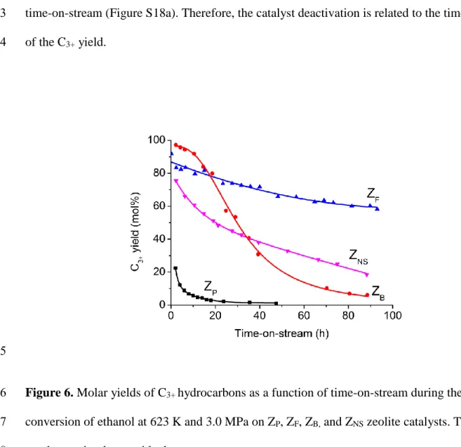
time-on-stream (Figure S18a). Therefore, the catalyst deactivation is related to the time evolution 3
of the C3+ yield.
4
5
Figure 6. Molar yields of C3+ hydrocarbons as a function of time-on-stream during the
6
conversion of ethanol at 623 K and 3.0 MPa on ZP, ZF, ZB, and ZNS zeolite catalysts. The lines
7
are drawn simply to guide the eyes. 8
On the parent zeolite (Zp), the initial yield of C3+ is only 35 % (extrapolated value at zero
9
conversion) and decreases rapidly becoming negligible after only 20 h (Figure 6). On ZB, the
10
initial C3+ yield is slightly less than 100% (Figure 6), but the catalyst deactivates rapidly and
11
yields almost no C3+ after 90 h on stream. On ZNS, the initial C3+ yield is lower than ZB but quite
12
high considering its much lower Brønsted acid site concentration. However, its deactivation rate 13
21 is much lower than ZB: after 90 h on stream, the C3+yield decreases to ca. 20 mol.% while it was
1
almost zero on ZB. The direct synthesis of a hierarchical zeolite using a complex surfactant is an
2
efficient, albeit expensive, way of minimizing deactivation. ZF, although not the catalyst with the
3
best initial C3+ yield retains it much longer as it deactivates much slower than ZB and ZNS (Figure
4
6); after 90 h of TOS, it still produces a substantial C3+ yield, ca. 60 mol.%.
5
The unbiased NH4F etching of a micrometer-sized ZSM-5 zeolite leads to a diffusion path
6
length similar to that of nanosized one. Indeed, the stability of ZF is similar, or even higher for
7
longer reaction time, to that on a commercial zeolite with a crystal size of 45 nm [31]. See also 8
Figure S19 in the present work. The superior stability of ZF on a nanoscale zeolite can be related
9
to both a high intracrystalline mesoporous volume (0.31 cm3.g-1) and quasi-perfect connectivity 10
with the microporous network, a consequence of single crystal nature of house-of-cards-like 11
material. As ZF is devoid of defects, contrariwise on ZNS, the immobilization and growth of coke
12
precursors are mitigated. Therefore the catalyst is more stable. On the other hand, as the caustic 13
leaching divides by only four the diffusion path length as shown by the desorption experiments 14
[47], the gain in stability is rather limited. 15
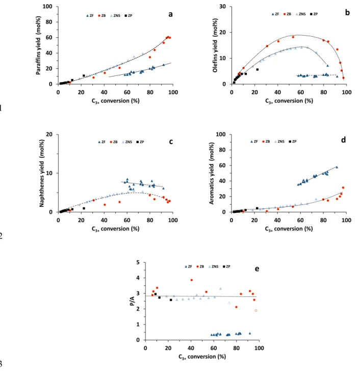
The molar yields of the paraffins (P), olefins (O), naphthenes (N), and aromatics (A), as well 16
as the paraffins to aromatics molar ratio (P/A), are reported as a function of the C3+ yield and
17
time-on-stream in Figure 7 and Figure S18b-f, respectively. As far as product distribution is 18
concerned ZP, ZNS and ZP give the same product selectivity for the same C3+ yield, meaning that
19
the reactions involved are identical, even during the deactivation and regardless of the acid 20
properties of the three catalysts. It is worth to note that a difference exists only on ZB with a yield
21
in O3+. Yields in N and O3+ pass through a high yielding maximum in C3+, while those in P and
22
A increase exponentially. Regardless of C3+ yield the paraffins to aromatics molar ratio (P/A) is
22 ca. 3 (Figure 7e), indicative of hydrogen transfer between naphthene and olefins (Scheme 1). The 1
initial low value of P/A ratio (open symbol in figure 7e) is due to coke formation. 2
3
4
Scheme 1. The hydrogen transfer reaction between naphthene and olefins.
5
In sharp contrast, ZF shows considerably higher aromatic and naphthene yields than ZB and
6
ZNS, while its paraffin yield is low (Figure 7a, c, d). Apparently, hydrogen transfer reactions are
7
substantially suppressed in this catalyst. Its P/A is lower than 0.5 (Figure 7e), implying that on 8
the NH4F treated zeolite, aromatics are formed by a monomolecular protolytic dehydrogenation.
9
Lercher and coworkers [48] have shown that a high ratio of Brønsted acid sites to Lewis acid 10
sites (BAS/LAS) minimizes the alkenes concentration and causes high hydride transfer (HT) 11
activity. Yet on ZF catalyst, HT is limited although the house-of-cards-like catalyst possesses the
12
highest BAS/LAS ratio. Lercher et al. [49] also demonstrated that the rate determining step for 13
dehydrogenation activity of alkane on H-ZSM-5 is represented by olefin desorption from the 14
catalyst surface which is promoted by a short diffusion path length. It is worth mentioning that 15
the products selectivity of ZF is very close to nanometer-sized ZSM-5 zeolite (Figure S20),
16
confirming that the diffusion path length is limited to a few nanometers on both zeolites. 17
23 0 20 40 60 80 100 0 20 40 60 80 100 P ar af fi ns y ield ( m ol% ) C3+conversion (%) ZF ZB ZNS ZP a 0 10 20 30 0 20 40 60 80 100 Ol ef ins y ie ld ( m ol% ) C3+conversion (%) ZF ZB ZNS ZP b 1 0 10 20 0 20 40 60 80 100 Na ph thene s yi eld ( m ol % ) C3+conversion (%) ZF ZB ZNS ZP c 0 20 40 60 80 100 0 20 40 60 80 100 Ar om at ic s yi el d ( m ol% ) C3+conversion (%) ZF ZB ZNS ZP d 2 0 1 2 3 4 5 0 20 40 60 80 100 P/ A C3+conversion (%) ZF ZB ZNS ZP e 3
Figure 7. Ethanol transformation at 623 K and 3.0 MPa on ZP, ZF, ZB and ZNS zeolite: (a) molar
4
yields of paraffins (P), (b) olefins (O3+), (c) naphthenes (N), (d) aromatics (A), and (e) molar P/A
5
ratio catalysts as a function of C3+ conversion. The lines are drawn simply to guide the eyes.
6
The coke content, the evolution of the number of acid sites (Brønsted and Lewis) and pore 7
volumes accessible to nitrogen after more than 48 h of reaction are gathered in Table 2. The coke 8
24 content is around 13 wt % on ZP after 48 h of reaction. NH4F etching has no impact on the coke
1
level, while on the alkaline leached ZB catalyst, coke grows continuously to reach a level almost
2
twice as high as its parent. On ZNS, although its Brønsted acid site concentration is 4 times lower
3
than on ZP, coke content is quite similar. The residual acidity (Brønsted and Lewis), after
4
deactivation, is very low for all samples. An important decrease of micropore volume occurs on 5
all zeolites. On ZNS which is the least acidic catalyst, the loss of microporosity is only 25%. The
6
coked ZF and ZNS catalysts, despite a near total loss of acidity, keep converting ethanol to C3+
7
hydrocarbons (60 %, and 20 %, respectively, (Figure 6)); ethanol transformation occurring 8
probably by pore mouth catalysis on hybrid active sites (immobilized carbocations) by a carbon 9
pool mechanism [31]. 10
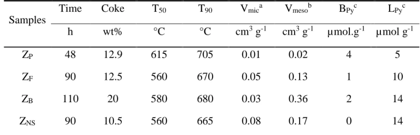
Table 2: Coke content, T50 and T90 (temperatures required to remove, by combustion, 50% and
11
90% of coke respectively), pore volumes and acidity of ZP, ZF, ZB and ZNS zeolite spent
12
catalysts. 13
Samples
Time Coke T50 T90 Vmica Vmesob BPyc LPyc
h wt% °C °C cm3 g-1 cm3 g-1 µmol.g-1 µmol g-1 ZP 48 12.9 615 705 0.01 0.02 4 5 ZF 90 12.5 560 670 0.05 0.13 1 10 ZB 110 20 580 680 0.03 0.36 2 14 ZNS 90 10.5 560 665 0.08 0.17 0 14 at-plot. bV
total – Vmic (Vtotal: the volume absorbed at p/p0 = 0.99). cThe Brønsted acidity (BPy) and
14
Lewis acidity (LPy) determined by pyridine sorption.
15
Differences in the activity and stability between ZP, ZB, ZF, and ZNS are related to changes in
16
the carbon pool composition. The composition of the coke trapped in the zeolite micropores, i.e., 17
25 internal coke, is determined by mineralizing the zeolite and subsequently analyzing the organic 1
phase after a liquid-liquid extraction with CH2Cl2 [50]. Coke molecules can be lumped in four
2
families according to their number of aromatic rings: alkylbenzenes (I), alkyl naphthalenes (II), 3
alkyl-phenanthrenes or -anthracenes (III) and alkylpyrenes (IV). The sizes of all compounds 4
trapped in the micropores vary between the dimensions of the pore openings (0.55 nm) and 5
channel intersections (~1 nm) of H-ZSM-5. The coke on ZP and ZB contain representatives of all
6
families. A simpler and lighter coke distribution is found on ZF and ZNS, where families I and III
7
dominate (Figure S21); such a coke composition is similar to that reported elsewhere on nano-8
sized zeolite [31]. The average molar mass of coke trapped in the micropores, calculated from 9
these compositions, is 200 g mol-1 for ZP and ZB, and 180 g mol-1 for ZF and ZNS.
10
Taking this average molar mass of 200 g mol-1 for the coke molecules trapped inside the 11
micropores (ca. 13 wt % on the ZP catalysts), its concentration is ca. 645 mol g-1, corresponding
12
to the amount of Brønsted acid sites on the fresh zeolite. Coking is therefore mainly a site 13
poisoning effect, further confirmed by a complete disappearance of the bridged OH groups 14
(Figure S22). Assuming that on all hierarchical zeolites, one coke molecule poisons only one 15
protonic site, the coke trapped within the micropores and that located in the mesopores can be 16
estimated. The results are reported in the bar chart on Figure 8. The most significant 17
accumulations of coke on the mesopores are for the caustic leached micron-sized zeolite (ZB) and
18
the nanosheet zeolite (ZNS), reaching up to 55% and ca. 75% of the total coke, on the other hand,
19
it is limited to 16% on the catalyst free of defect (ZF) and as expected, almost zero on the parent
20
zeolite. The accumulation of coke in mesopores is likely related to the quality of the crystals. The 21
increased number of silanols and Lewis acid sites on ZB and ZNS are prone to trap desorbed
22
products [51–53] as confirmed by the disappearance of silanol groups on spent catalysts (Figure 23
26 S22). Taking a coke density of 1.1 g cm-3, the volume of coke in the micropores corresponds to 1
the loss of micropore volume measured by nitrogen adsorption (Figure 8). These calculated 2
values are very close to the experimental data, highlighting the relevance of this procedure to 3
discriminate between internal and external coke contents. 4
5
6
Figure 8. Estimation of the coke distribution between micropores and mesopores on ZP, ZF, ZB
7
and ZNS zeolite spent catalysts
8
In addition, the coke light-off performances of the spent catalysts are compared in Table 2 9
where temperatures required to combust 50% (T50) and 90% (T90) of the coke are reported. T50
10
and T90 are both lower on ZB than on ZP (-35 °C and -25 °C respectively ) and much lower on
11
ZNS and ZF (-55 °C). The differences are related to a higher accessibility (difusion) of oxygen to
12
the coke molecules trapped in the micropores. The house-of-cards-like zeolite, already the best 13
27 catalyst (cumulative performance due to its time stability) is as good as a nanosheet one for 1
regeneration. 2
The ETH reaction illustrates the superior stability and selectivity of ZF, a house-of-cards-like
3
ZSM-5 catalyst, although other hierarchical zeolites, ZB and ZNS possess higher external surface
4
area and mesopore volume. The nano-sheet zeolite ZNS with a higher Si/Al ratio of 37 and lower
5
acid site density displays a remarkably high initial C3+ yield and was once expected to be a
6
superior candidate for ETH reactions [54] but lacks stability as shown in this study. The ZF
7
catalyst outperforms both ZB and ZNS in the present study, but the ZNS hierarchization procedure
8
brings superior performances than a micron-sized zeolite, ZP (Figure 6). Zeolite acidity and
9
mesoporosity cannot alone fully explain the differences in catalytic performances discussed 10
above. Based on our detailed comparison of the hierarchical zeolites, we propose that, in addition 11
to mesopore size, shape, uptake capacity and connectivity, the quality of the hierarchical zeolites 12
(micropore accessibility, absence of defects [silanol nests], Lewis acidity) also play important 13
roles in the ETH reaction. The higher catalytic performances of NH4F leached zeolites could also
14
be related to their ability to dehydrogenate naphthenic compounds (Figure 7); this 15
monomolecular reaction requires less space than the bimolecular hydrogen transfer occurring on 16
the caustic leached zeolite and nano-sheet zeolite. The absence of defects combined with a small 17
diffusion pathlength inside the microporosity by retarding the transformation of the desired 18
active carbon pool to unwanted coke, slows catalyst deactivation. The presence of numerous 19
silanol groups, on the other hand, traps coke precursors on the surface, promoting a rapid catalyst 20
deactivation by a fast accumulation of aromatic compounds. Indeed, as coke formation is a 21
genuine shape selective reaction, the availability of more space favors the production of larger 22
molecules, coke, i.e. an inactive carbon pool. These results highlight that, in addition to the 23
28 loosely defined “mesopore quality” [21], the surface quality of the remaining microporous
1
crystal domains determines the catalytic performance of hierarchically structured zeolite crystals. 2
Conclusion
3
Single house-of-cards-like ZSM-5 crystals were prepared by a top-down approach using a 4
novel unbiased chemical etching with an NH4F solution. Such an etching extracts Si and Al at
5
similar rates and preferentially removes less-stable defect zones in the crystals. The process is 6
therefore controlled by the number of intergrowths, the structural stress and the nanocrystalline 7
domains with well-defined grain boundaries, i.e. the history of the zeolite synthesis. Such a 8
unique dissolution behavior is inherently related to the growth process where simultaneous 9
monomer-by-monomer addition and oriented attachment take place [42]. The unbiased NH4F
10
dissolution leads to the preferential extraction of misoriented and more vulnerable to chemical 11
attack nanocrystalline domain followed by progressive etching of the remaining part of the 12
crystals, which is more resistant due to the limited number of structural defects. This dissolution 13
proceeds by a layer-by-layer mechanism following the rectangular features of previously 14
extracted nanodomains, thus the well shaped cavities grown in size and connect each other 15
providing a house-of-cards-like morphology. 16
Such a hierarchical material is analogous to a collection of nanosized high quality crystals with 17
the same framework composition and Brønsted acidity of their parent. The high accessibility and 18
short diffusion pathlength offered by the house-of-cards-like morphology is therefore combined 19
with the intact native microporosity and acidity of their parent zeolite and does not require 20
expensive and one-off structure directing agents. The optimization of structural and chemical 21
parameters results in an excellent catalyst easier to regenerate, as demonstrated in the 22
29 challenging (deactivation prone) ethanol-to-hydrocarbon reaction. Indeed, regenerating
1
deactivated catalysts by controlled coke combustion often leads to, often overlooked, irreversible 2
changes due to the operating conditions (such an exothermic reaction produces steam near the 3
zeolite active sites and can lead to structural and chemical damages such as dealumination) of 4
this step. The performance of such single crystals house-of-cards-like catalysts is so far second to 5
none as it maintains its performance over longer periods of time and appears easier to regenerate, 6
which even outperforms the nanometer-sized zeolites (Figure S19). Noting that we have 7
previously concluded, based on the samples studied, that the reduction of crystal size is the most 8
efficient way to increase the performance of zeolites for applications such as alcohols to 9
hydrocarbons, and hence nano-zeolites are preferred [31]. 10
This study highlights that hierarchical zeolitic catalysts with superior performances can be 11
designed not only by promoting high accessibility and short diffusion to and from their active 12
sites, but also by retaining the crystallinity and acidity of their parents while keeping a minimum 13
level of defects. Since the presence of crystalline domains with well-defined grain boundaries is 14
a ubiquitous in zeolite materials, the preparation of single crystal house-of cards can be extended 15
to other zeolite types. Further insights in the hierarchization process of zeolites, either bottom-up 16
or top-down (this work) hold much potential to design ever bettter zeolite catalysts for current 17
and forthcoming applications [55]. 18
19
Supporting Information. Experimental details, the nitrogen physisorption isotherms, the
20
combined 3D models of zeolite body and pores, the additional SEM and TEM images and a 21
graphical representation of the house-of-cards-like architecture, the additional data of the 22
30 Ethanol-to-Hydrocarbons reaction, coke composition by GC analysis, and the IR spectra of the 1
coked zeolite samples. 2 Corresponding Author 3 *[email protected] 4 5 ACKNOWLEDGMENT 6
Zhengxing Qin acknowledges funding support from NSFC 21706285, China University of 7
Petroleum (East China) starting funding, and the Fundamental Research Funds for the Central 8
Universities (18CX02013A). ZQ, JPG and VV acknowledge funding from the French-Sino 9
International Laboratory (LIA) “Zeolites”. 10
11
REFERENCES 12
[1] Martínez C.; Corma A. Inorganic molecular sieves: Preparation, modification and industrial 13
application in catalytic processes. Coordination Chemistry Reviews 2011, 255, 1558-1580. 14
[2] Vermeiren W.; Gilson J.-P. Impact of Zeolites on the Petroleum and Petrochemical Industry. 15
Topics in Catalysis 2009, 52, 1131-1161. 16
[3] Vogt, E. T. C.; Weckhuysen, B. M. Fluid catalytic cracking: recent developments on the 17
grand old lady of zeolite catalysis, Chemical Society Reviews 2015, 44, 7342-7370. 18
[4] Tosheva, L.; Valtchev, V. Nanozeolites: Synthesis, Crystallization Mechanism, and 19
Applications. Chemistry of Materials 2005, 17, 2494-2513. 20
[5] Valtchev, V.; Tosheva, L. Porous Nanosized Particles: Preparation, Properties, and 21
Applications. Chemical Reviews 2013, 113, 6734-6760. 22
31 [6] Fan, W.; Snyder, M.; Kumar, S.; Lee, P.; Yoo, W.; McCormick, A.; Penn, R.; Stein, A.; 1
Tsapatsis, M. Hierarchical nanofabrication of microporous crystals with ordered 2
mesoporosity. Nature Materials 2008, 7, 984-991. 3
[7] Awala, H.; Gilson, J.-P.; Retoux, R.; Boullay, P.; Goupil, J.-M.; Valtchev, V.; Mintova, S. 4
Template-free nanosized faujasite-type zeolites. Nature Materials 2015, 14, 447-451. 5
[8] Valtchev, V.; Majano, G.; Mintova, S.; Perez-Ramirez, J. Tailored crystalline microporous 6
materials by post-synthesis modification. Chemical Society Reviews 2013, 42, 263-290. 7
[9] Hartmann, M.; Machoke, A. G.; Schwieger, W. Catalytic test reactions for the evaluation of 8
hierarchical zeolites. Chemical Society Reviews 2016, 45, 3313-3330. 9
[10] Smaihi, M.; Barida, O.; Valtchev, V. Investigation of the Crystallization Stages of LTA-Type 10
Zeolite by Complementary Characterization Techniques. European Journal of Inorganic 11
Chemistry 2003, 24, 4370-4377. 12
[11] Valtchev, V. Preparation of regular macroporous structures built of intergrown silicalite-1 13
nanocrystals. Journal of Materials Chemistry 2002, 12, 1914-1918. 14
[12] Tsapatsis, M. 2-dimensional zeolites. AIChE Journal. 2014, 60, 2374-2381. 15
[13] Corma, A.; Fornes, V.; Pergher, S. B.; Maesen, T. L. M.; Buglass, J. G. Delaminated zeolite 16
precursors as selective acidic catalysts. Nature 1998, 396, 353-356. 17
[14] Choi, M.; Cho, H. S.; Srivastava, R.; Venkatesan, C.; Choi, D.-H.; Ryoo, R. Amphiphilic 18
organosilane-directed synthesis of crystalline zeolite with tunable mesoporosity. Nature 19
Materials 2006, 5, 718-723. 20
[15] Choi, M.; Na, K.; Kim, J.; Sakamoto, Y.; Terasaki, O.; Ryoo, R. Stable single-unit-cell 21
nanosheets of zeolite MFI as active and long-lived catalysts. Nature 2009, 461, 246-249. 22
[16] Na, K.; Jo, C.; Kim, J.; Cho, K.; Jung, J.; Seo, Y.; Messinger, R. J.; Chmelka, B. F.; Ryoo, R. 23
32 Directing Zeolite Structures into Hierarchically Nanoporous Architectures. Science 2011, 1
333, 328-332. 2
[17] Zhang, X.; Liu, D.; Xu, D.; Asahina, S.; Cychosz, K. A.; Agrawal, K. V.; Al Wahedi, Y.; 3
Bhan, A.; Al Hashimi, S.; Terasaki, O.; Thommes, M.; Tsapatsis, M. Synthesis of Self-4
Pillared Zeolite Nanosheets by Repetitive Branching, Science 2012, 336, 1684-1687. 5
[18] van Donk, S.; Janssen, A. H.; Bitter, J. H.; de Jong, K. P. Generation, Characterization, and 6
Impact of Mesopores in Zeolite Catalysts. Catalysis Reviews-Science and Engineering 2003, 7
45, 297-319. 8
[19] Young D. A. Hydrocarbon conversion process and catalyst comprising a crystalline alumino-9
silicate leached with sodium hydroxide. US Pat. 3,326,797, assigned to Unocal, 1964. 10
[20] Gilson, J.-P.; Nanne, J. M.; Den Otter, G. J. Process for isomerizing hydrocarbons. EP 11
0398416, assigned to Shell, 1989. 12
[21] Milina, M.; Mitchell, S.; Crivelli, P.; Cooke, D.; Pérez-Ramírez, J. Mesopore quality 13
determines the lifetime of hierarchically structured zeolite catalysts. Nature Communications 14
2014, 5, 3922. 15
[22] Valtchev, V.; Balanzat, E.; Mavrodinova, V.; Diaz, I.; El Fallah, J.; Goupil, J.-M. High 16
Energy Ion Irradiation-Induced Ordered Macropores in Zeolite Crystals. Journal of the 17
American Chemical Society 2011, 133, 18950-18956. 18
[23] Qin, Z.; Gilson, J.-P.; Valtchev, V. Mesoporous zeolites by fluoride etching. Current Opinion 19
in Chemical Engineering 2015, 8, 1-6. 20
[24] Qin, Z.; Melinte, G.; Gilson, J.-P.; Jaber, M.; Bozhilov, K.; Boullay, P.; Mintova, S.; Ersen, 21
O.; Valtchev, V. The Mosaic Structure of Zeolite Crystals. Angewandte Chemie International 22
Edition 2016, 55, 15049-15052. 23
33 [25] Qin, Z.; Cychosz, K. A.; Melinte, G.; El Siblani, H.; Gilson, J.-P.; Thommes, M.; Fernandez, 1
C.; Mintova, S.; Ersen, O.; Valtchev, V. Opening the Cages of Faujasite-Type Zeolite. 2
Journal of the American Chemical Society 2017, 139, 17273-17276. 3
[26] Valtchev, V.; Gilson, J.-P.; Qin, Z. Method for the preparation of synthetic crystalline zeolite 4
materials with enhanced total pore volume. WO 2016005783 A1, assigned to CNRS, 2016. 5
[27] Breck, D. W.; Skeels, G. W. Silicon substituted zeolite compositions and process for 6
preparing same. U.S. Patent 4,503,023, assigned to Union Carbide. 1985. 7
[28] Skeels, G. W.; Breck, D. W. in Proceedings of the Sixth International Zeolite 8
Conference,Olson, D.; Bisio, A. Eds.; Butterworths, Guildford, UK, 1984; p. 87. 9
[29] Chen, X.; Todorova, T.; Vimont, A.; Ruaux, V.; Qin, Z.; Gilson, J.-P.; Valtchev, V. In situ and 10
post-synthesis control of physicochemical properties of FER-type crystals. Microporous and 11
Mesoporous Materials 2014, 200, 334-342. 12
[30] Ajot, H.; Joly, J. F.; Lynch, J.; Raatz, F.; Caullet, P. Formation of Secondary Pores in Zeolites 13
During Dealumination: Influence of The Crystallographic Structure and Of the Si/Al Ratio. 14
In Studies in Surface Science and Catalysis, Rodriguez-Reinoso, F., Rouquerol, J., Sing, K. 15
S. W., Unger, K. K., Eds.; Elsevier: 1991; Vol. 62, p 583-590. 16
[31] Lakiss, L.; Ngoye, F.; Canaff, C.; Laforge, S.; Pouilloux, Y.; Qin, Z.; Tarighi, M.; Thomas, 17
K.; Valtchev, V.; Vicente, A.; Pinard, L.; Gilson, J.-P.; Fernandez, C. On the remarkable 18
resistance to coke formation of nanometer-sized and hierarchical MFI zeolites during 19
ethanol to hydrocarbons transformation. Journal of Catalysis 2015, 328, 165-172. 20
[32] Boltz, M.; Losch, P.; Louis, B.; Rioland, G.; Tzanis, L.; Daou, T. J. MFI-type zeolite 21
nanosheets for gas-phase aromatics chlorination: a strategy to overcome mass transfer 22
limitations. RSC Advances 2014, 4, 27242-27249. 23
34 [33] Thommes, M.; Kaneko, K.; Neimark Alexander, V.; Olivier James, P.; Rodriguez-Reinoso, F.; 1
Rouquerol, J.; Sing K. S.W. Physisorption of gases, with special reference to the evaluation 2
of surface area and pore size distribution (IUPAC Technical Report). Pure and Applied 3
Chemistry 2015, 87, 1051-1069. 4
[34] Kortunov, P.; Vasenkov, S.; Kärger.; J. Valiullin, R.; Gottschalk, P.; Fé Elía, M.; Perez, M.; 5
Stöcker, M.; Drescher, B.; McElhiney, G.; Berger, C.; Gläser, R.; Weitkamp, J. The role of 6
mesopores in intracrystalline transport in USY zeolite: PFG NMR diffusion study on various 7
length scales. Journal of the American Chemical Society, 2005, 127, 13055-13059. 8
[35] Groen, J. C.; Bach, T.; Ziese, U.; Paulaime-van Donk, A. M.; de Jong, K. P.; Moulijn, J. A.; 9
Pérez-Ramírez, J. Creation of Hollow Zeolite Architectures by Controlled Desilication of Al-10
Zoned ZSM-5 Crystals. Journal of the American Chemical Society, 2005, 127, 10792-10793. 11
[36] Mei, C.; Liu, Z.; Wen, P.; Xie, Z.; Hua, W.; Gao, Z. Regular HZSM-5 microboxes prepared 12
via a mild alkaline treatment. Journal of Materials Chemistry, 2008, 18, 3496-3500. 13
[37] Danilina, N.; Krumeich, F.; Castelanelli, S. A.; van Bokhoven, J. A. Where Are the Active 14
Sites in Zeolites? Origin of Aluminum Zoning in ZSM-5. The Journal of Physical Chemistry 15
C, 2010, 114, 6640-6645. 16
[38] Suga, M.; Asahina, S.; Sakuda, Y.; Kazumori, H.; Nishiyama, H.; Nokuo, T.; Alfredsson, V.; 17
Kjellman, T.; Stevens, S. M.; Cho, H. S.; Cho, M.; Han, L.; Che, S.; Anderson, M. W.; 18
Schüth, F.; Deng, H.; Yaghi, O. M.; Liu, Z.; Jeong, H. Y.; Stein, A.; Sakamoto, K.; Ryoo, R.; 19
Terasaki, O. Recent progress in scanning electron microscopy for the characterization of fine 20
structural details of nano materials. Progress in Solid State Chemistry, 2014, 42, 1-21. 21
[39] Wang, Y.; Lin, M.; Tuel, A. Hollow TS-1 crystals formed via a dissolution–recrystallization 22
process. Microporous and Mesoporous Materials, 2007, 102, 80-85. 23
35 [40] Qin, Z.; Lakiss, L.; Gilson, J. P.; Thomas, K.; Goupil, J. M.; Fernandez, C.; Valtchev, V. 1
Chemical Equilibrium Controlled Etching of MFI-Type Zeolite and Its Influence on Zeolite 2
Structure, Acidity, and Catalytic Activity. Chemistry of Materials 2013, 25, 2759-2766. 3
[41] Anderson, M. W.; Agger, J. R.; Hanif, N.; Terasaki, O. Growth models in microporous 4
materials. Microporous and Mesoporous Materials, 2001, 48, 1-9. 5
[42] Meza, L. I.; Anderson, M. W.; Agger, J. R.; Cundy, C. S.; Chong, C. B.; Plaisted, R. J. 6
Controlling Relative Fundamental Crystal Growth Rates in Silicalite: AFM Observation. 7
Journal of the American Chemical Society, 2007, 129, 15192-15201. 8
[43] Lupulescu, A. I.; Rimer, J. D. In Situ Imaging of Silicalite-1 Surface Growth Reveals the 9
Mechanism of Crystallization. Science, 2014, 344, 729-732. 10
[44] De Yoreo, J. J.; Gilbert, P. U. P. A.; Sommerdijk, N. A. J. M.; Penn, R. L.; Whitelam, S.; 11
Joester, D.; Zhang, H.; Rimer, J. D.; Navrotsky, A.; Banfield, J. F.; Wallace, A. F.; Michel, F. 12
M.; Meldrum, F. C.; Cölfen, H.; Dove, P. M. Crystallization by particle attachment in 13
synthetic, biogenic, and geologic environments. Science, 2015, 349, aaa6760. 14
[45] Lønstad Bleken, B.-T.; Mino, L.; Giordanino, F.; Beato, P.; Svelle, S.; Lillerud, K. P.; 15
Bordiga, S. Probing the surface of nanosheet H-ZSM-5 with FTIR spectroscopy. Physical 16
Chemistry Chemical Physics 2013, 15, 13363-13370. 17
[46] Derouane, E. G.; Nagy, J. B.; Dejaifve, P.; van Hooff, J. H. C.; Spekman, B. P.; Védrine, J. C.; 18
Naccache, C. Elucidation of the mechanism of conversion of methanol and ethanol to 19
hydrocarbons on a new type of synthetic zeolite. Journal of Catalysis, 1978, 53, 40-55. 20
[47] Meunier, F. C.; Verboekend, D.; Gilson, J.-P.; Groen, J. C.; Pérez-Ramírez, J. Influence of 21
crystal size and probe molecule on diffusion in hierarchical ZSM-5 zeolites prepared by 22
desilication. Microporous and Mesoporous Materials, 2012, 148, 115-121. 23
36 [48] Feller, A.; Guzman, A.; Zuazo, I.; Lercher, J. A. On the mechanism of catalyzed 1
isobutane/butene alkylation by zeolites. Journal of Catalysis, 2004, 224, 80-93. 2
[49] Narbeshuber, T. F.; Brait, A.; Seshan, K.; Lercher, J. A. Dehydrogenation of Light Alkanes 3
over Zeolites. Journal of Catalysis, 1997, 172, 127-137. 4
[50] Magnoux, P.; Roger, P.; Canaff, C.; Fouche, V.; Gnep, N. S.; Guisnet, M. New Technique for 5
the Characterization of Carbonaceous Compounds Responsible for Zeolite Deactivation. In 6
Studies in Surface Science and Catalysis, Delmon, B., Froment, G. F., Eds.; Elsevier: 1987; 7
Vol. 34, p 317-330. 8
[51] Barbera, K.; Bonino, F.; Bordiga, S.; Janssens, T. V. W.; Beato, P. Structure–deactivation 9
relationship for ZSM-5 catalysts governed by framework defects. Journal of Catalysis 2011, 10
280, 196-205. 11
[52] Thibault-Starzyk, F.; Vimont, A.; Gilson, J.-P. 2D-COS IR study of coking in xylene 12
isomerisation on H-MFI zeolite. Catalysis Today 2001, 70, 227-241. 13
[53] Lee, K.; Lee, S.; Jun, Y.; Choi, M. Cooperative effects of zeolite mesoporosity and defect 14
sites on the amount and location of coke formation and its consequence in deactivation. 15
Journal of Catalysis 2017, 347, 222-230. 16
[54] Madeira, F. F.; Tayeb, K. B.; Pinard, L.; Vezin, H.; Maury, S.; Cadran, N. Ethanol 17
transformation into hydrocarbons on ZSM-5 zeolites: Influence of Si/Al ratio on catalytic 18
performances and deactivation rate. Study of the radical species role. Applied Catalysis A: 19
General 2012, 443–444, 171-180. 20
[55] Ennaert, T.; Van Aelst, J.; Dijkmans, Jan.; De Clercq, R.; Schutyser, W.; Dusselier, M.; 21
Verboekend, D.; Sels, B. F. Potential and Challenges of Zeolite Chemistry in the Catalytic 22
Conversion of Biomass. Chemical Society Reviews 2016, 45, 584-611. 23
37 1
38 SYNOPSIS (Word Style “SN_Synopsis_TOC”).
1