HAL Id: hal-01909972
https://hal.archives-ouvertes.fr/hal-01909972
Submitted on 9 Nov 2018
HAL is a multi-disciplinary open access
archive for the deposit and dissemination of
sci-entific research documents, whether they are
pub-lished or not. The documents may come from
teaching and research institutions in France or
abroad, or from public or private research centers.
L’archive ouverte pluridisciplinaire HAL, est
destinée au dépôt et à la diffusion de documents
scientifiques de niveau recherche, publiés ou non,
émanant des établissements d’enseignement et de
recherche français ou étrangers, des laboratoires
publics ou privés.
confined granular medium by injection of a viscous
liquid or gas
Øistein Johnsen, Christophe Chevalier, Anke Lindner, Renaud Toussaint, Eric
Clement, Knut Jørgen Måløy, Eirik G. Flekkøy, Jean Schmittbuhl
To cite this version:
Øistein Johnsen, Christophe Chevalier, Anke Lindner, Renaud Toussaint, Eric Clement, et al..
De-compaction and fluidization of a saturated and confined granular medium by injection of a viscous
liquid or gas. Physical Review E : Statistical, Nonlinear, and Soft Matter Physics, American Physical
Society, 2008, 78 (5), pp.051302. �10.1103/PhysRevE.78.051302�. �hal-01909972�
Decompaction and fluidization of a saturated and confined granular medium
by injection of a viscous liquid or gas
Ø. Johnsen,1,2,3C. Chevalier,1,4A. Lindner,1 R. Toussaint,3 E. Clément,1K. J. Måløy,2E. G. Flekkøy,2 and J. Schmittbuhl3
1
Laboratoire de Physique et Mécanique des Milieux Hétégogènes (PMMH), UMR 7636 CNRS, ESPCI, Universités Paris 6 et 7, 10, rue Vauquelin, 75231 Paris Cedex 05, France
2
Advanced Materials and Complex Systems (AMCS), Department of Physics, University of Oslo, P. O. Box 1048 Blindern, 0316 Oslo, Norway
3Institute of Globe Physics in Strasbourg (IPGS), UMR 7516 CNRS, Université Louis Pasteur, 5 rue Descartes,
F-67084 Strasbourg Cedex, France
4
Université Paris Est, LCPC, MSRGI, 58 boulevard Lefebvre, 75015 Paris, France
共Received 19 June 2008; published 6 November 2008兲
We compare quantitatively two experimental situations concerning injection of a miscible fluid into an initially jammed granular medium saturated with the same fluid, confined in a Hele-Shaw cell. The two experiments are identical, apart from the interstitial and injected fluid, which is in one case air injected into a dry granular packing, and in the other case silicone oil injected into a dense suspension. In spite of the strong differences regarding the nature of the two fluids, strikingly similar dynamical and geometrical features are identified as functions of the control parameters: cell thickness and applied fluid injection pressure. In both cases an initial hydrodynamically driven decompaction process controls the unjamming and prepares the final displacement process characterized by fingerlike patterns empty of grains. The pattern shapes are comparable. In addition, the mobilities of the coupled fluid-grain flow, rescaled by the interstitial fluid viscosity and grain diameter squared, are of the same range and behave comparably. The mobility proves to depend on the initial solid fraction of the medium. Subtle differences are observed in geometrical aspects like the finger width with respect to the control parameters.
DOI:10.1103/PhysRevE.78.051302 PACS number共s兲: 45.70.Qj, 47.15.gp, 47.55.Kf
I. INTRODUCTION
The hydrodynamic instabilities and fingerlike patterns emerging as a less viscous fluid displaces a more viscous fluid in Hele-Shaw cell configurations 关1兴 have been
exten-sively studied and vastly documented for both Newtonian 关2–5兴 and non-Newtonian fluids 关6–11兴. Another flow
situa-tion with a well-established physical descripsitua-tion of its own is that of a fluid flow through a fixed porous medium 关12兴.
However, where these two systems merge, the miscible case of fluid injection into a deformable porous phase close to the jamming transition关13–18兴, the solid grains can behave as a
conducting porous matrix, or can be suspended, forming an effective fluid. The transition between the two flow types has been studied during fluid injection into a loosely packed granular medium 关19,20兴 or a dense granular suspension
关21兴, and is similarly observed when a fluid is retracted
through a granular matrix关22,23兴. The fluid displacement of
grains by injection is an unstable process leading to the for-mation of fingerlike patterns 关19,20,24,25兴, visually quite
similar to those found for non-Newtonian fluids. Coupled fluid-grain flows and fluid-grain interactions, on which these processes rely, are rather poorly understood and their study is in its infancy. The case of bubbling instability in fluidized beds under gravity is perhaps the most studied issue related to this case关26–37兴. Nevertheless, for a very dense granular
medium the situation is quite complex, essentially due to the nature of a granular material: it may act as a complex fluid and can jam at higher concentrations and become a solid porous matrix.
In practice, the problem addressed is an important issue since many industrial or geophysical applications rely on
such an elementary process. Internal piping erosion due to flow concentration into tubular macropores during runoff may ultimately cause failure of soils in, e.g., dikes, embank-ments, and dams 关38兴. In nature, this type of erosion may
also trigger hill-slope instabilities关39,40兴, as well as sudden
and potentially catastrophic drainage of the water contained in calderas关41兴, or in natural lakes formed after earthquakes.
In the present paper we present two experiments devel-oped in parallel due to common interest in the following situation: injection of a fluid into a loosely consolidated granular packing with a solid fraction brought close to the random close packed 共RCP兲 limit 关42兴. We study the
fluidi-zation process of an initially jammed granular medium. Two simple model realizations of the miscible injection problem are considered: the granular material, consisting of monodisperse polystyrene spheres, is confined in a horizon-tal Hele-Shaw cell, ensuring identical situations as far as geometry is concerned. The injection is made with either air into the initially densely packed and dry assembly of spheres, or by a silicone oil invading a dense suspension made with the same granular material and the same silicone oil as injected. At sufficiently high overpressures, the drag exerted by the permeating fluid over the weakly consolidated granular medium mobilizes the grains. The goal of this study is to classify and describe quantitatively the mobilization of the initially jammed granular medium and the patterns emerging during this fluidization process, and comparatively reveal similarities and differences due to the nature of the surrounding and injected fluid.
The paper is organized as follows. First, in Sec. II the experimental setup and the principle of the injection
ments are described. Then in Sec. III the aim is to character-ize the evolution of the unjamming process of typical experi-ments: decompaction dynamics and its role on the subsequent selection of the pure fluid fingerlike patterns emerging in the dense matrix. The flow properties and geo-metrical features of these fingerlike patterns are discussed in Sec. IV, before we summarize and address final conclusions in Sec. V.
II. EXPERIMENTAL SETUP
The experiments are performed in a linear Hele-Shaw cell 关1兴 as illustrated in Fig.1. A straight channel of rectangular section with a width W = 6 cm and a length of L = 30 cm is cut out of a Mylar sheet of calibrated thickness. The cell thickness is b = 0.85, 1.15, 1.70, or 2.30 mm. The Mylar sheet is sandwiched between two thick glass plates acting as spacers and ensuring that three of the sides of the channel are impermeable. The end of the channel is left open and will be referred to as the outlet. Opposite to the outlet there is an injection point 共쏗=7 mm兲 in the upper plate positioned 1 cm from the impermeable boundary, referred to as the in-let.
The granular medium in the cell is saturated with a given interstitial fluid as described in Secs. II A and II B. In this work, we consider two cases with clearly distinct fluids: air 共compressible, viscosity air= 1.8⫻10−5 Pa s兲, and silicone oil 共incompressible, viscosity oil= 5.0⫻10−3 Pa s兲. The space around the inlet is initially filled with the same fluid as the interstitial one. This space acts as a pressure chamber. At the beginning of the experiment, the fluid injection starts at a given injection pressure Pi=⌬P+ Patm.⌬P is the fluid
over-pressure with respect to atmospheric over-pressure Patm, at the outlet.⌬P is applied by manually opening a valve. Opening the valve fully takes ⬃0.02 s. Thus, the pressure profile of the injection is close to a step function: after the onset,⌬P is maintained constant throughout the experiment. The probed range of the applied ⌬P is between ⬃10 and ⬃200 mbars for the dense packing prepared by tapping.
Complementary to the comparative study involving two distinct fluids for otherwise similar conditions, we have per-formed experiments with an initially less dense packing of the granular material. In this case, the cell thickness is b = 0.70, 1.10, and 2.1 mm, and ⌬P is in the range ⬃2 to ⬃30 mbars.
To record the motion of the grains, images are obtained by reflection, with the use of a dark background to increase the contrast between the zones free of grains and the granular regions. The setup is illuminated from above using two 800 W halogen projectors, and images of 400⫻1600 pixels are acquired at a frequency of 500 images per second, using a Phantom V9 high-speed camera for the air-grain experi-ments, and for the oil-grain system a Prosilca EC1280 charge-coupled device 共CCD兲 camera is used at a sample frequency of ten images per second, at a resolution of 1280⫻400 pixels.
A. Sample preparations: Air-grain system
The granular medium consists of spherical monodisperse polystyrene beads 共Dynoseeds兲 with a diameter d = 80⫾3m, and density grain= 1.05⫾0.01 g cm−3. To en-sure a good reproducibility of the experiments, the following preparation stages were adopted to put the granular medium into place: the cell is placed vertically and the grains are introduced via the outlet. Once the proper quantity is intro-duced, a Mylar plate matching the width and height of the channel is inserted⬃6 cm into the channel. This will prevent the grains from moving through the outlet during the sample preparation. The cell is then tilted upside down, which brings the granular medium against the Mylar plate, and frees space around the inlet. The granular material is further compacted by tapping the filled cell in a defined manner, which ulti-mately brings the packing into a dense initial state with solid fraction 0=共62⫾1兲%, found by weighing the grains and measuring the volume they occupy in the cell. This is close to the random close packed limit关42兴.
For the complementary experiments the procedure is the same, except that in this case the particles are simply as-sembled in the cell under gravity without mechanically im-posing any further compaction. The solid fraction is 0 =共56⫾1兲%.
During the sample preparation solid contacts between the grains are established and friction forces from the walls on the grains are mobilized, pointing toward the inlet. The preparation stages produce a granular sample with a length L0= 18 cm. The grain-free zone around the inlet is about ⬃6 cm and the air-grain boundary facing the inlet is reason-ably straight. This interface is referred to as the inner bound-ary. The cell is then brought into a horizontal position and the Mylar plate used during the preparation is removed, leav-ing a straight grain-air boundary facleav-ing the outlet. We refer to this boundary as the outer boundary.
For the experiments performed with air as the interstitial fluid, control of the humidity of the experimental environ-ment during sample preparations is important. The interac-tions between ⬃80-m-sized beads are sensitive to the hu-midity of the surroundings: in very dry conditions,
FIG. 1. 共Color online兲 Experimental setup. A closed channel is made between two glass plates with three impermeable side bound-aries and one open共right兲. Either air or silicone oil is injected at pressure Pi into, respectively, a dry assembly of grains, or grains
saturated with the same type of silicone oil. Around the inlet共left part of the cell兲 there is a grain-free zone occupied by pure fluid. The region ahead of the grain and fluid and up to the outlet 共far right兲 is occupied by air at atmospheric pressure for both cases.
electrostatic forces play a role, while under excessively hu-mid conditions, capillary bridges form between neighboring beads, resulting in small but significant cohesive forces. To ensure the reproducibility of these individual interactions, the relative humidity of the air was kept between 30% and 40%.
B. Oil-grain system
For the oil-grain system the same beads and cells are used. An identical sample preparation procedure to obtain the dense packing for the air-grain is applied. But before remov-ing the Mylar plate that blocks the outlet a different final step is performed: imbibition of the granular medium with the silicone oil. Note that, in order to imbibe the medium suc-cessfully without trapping air bubbles and to avoid rear-rangement of grains leading to large density heterogeneities within the granular matrix, the packing fraction must be near the close packed limit. Hence, only the dense initial packing is obtainable for the oil-grain case.
The granular medium is imbibed with a silicone oil Rhodorsil 47V05 from Rhodia Silicones with a viscosity oil= 5.0⫻10−3 Pa s, as given by the supplier and measured with a Thermo-Haake rheometer. The oil is introduced via the inlet from an oil reservoir at constant overpressure. Dur-ing imbibition of oil into the granular medium one can ob-serve a propagating imbibition front. 共Note that the Mylar plug prevents the grains from moving and oil from escaping but is permeable to air.兲 The imbibition front is a straight line, indicating a homogeneous porosity of the dry jammed
grains and validating our preparation step. When measuring the velocity of the imbibition front as a function of the ap-plied pressure gradient, one can deduce the permeability of the porous medium关12兴. Applying the Carman-Kozeny
rela-tion 关43兴 the solid fraction estimation is 0⬃60%, which
agrees with the solid fraction obtained by weighing the grains and measuring the occupied volume of the granular medium. Once the porous medium is completely immersed the pressure is reduced to atmospheric pressure 共correspond-ing to a zero pressure gradient兲 and the Mylar plug is re-moved. The initial state consists then of a zone of grains fully immersed in a silicone oil and limited by two well-defined interfaces. The interface between the pure oil and the immersed granular medium facing the inlet is referred to as the inner boundary and the interface between the granular medium and air, facing the outlet, is referred to as the outer boundary. Note that an oil-grain-air interface at the outer boundary is chosen out of reproducibility considerations. This leads to a difference in the boundary conditions by the presence of interfacial surface tension. The oil and the grains are close to density matched; thus, sedimentation can be ne-glected.
III. EMERGING PATTERNS A. Typical experiments
Figures 2共a兲 and 2共e兲 show images respectively of the air-grain and the oil-grain systems just before injection共at t0兲 for cell thickness b = 1.15 mm, at a comparable⬃60% initial
FIG. 2. Typical experiments. The left column shows an air-grain experiment at⌬Pair= 93 mbar and b = 1.15 mm. In the right column an
oil-grain experiment at⌬Poil= 85 mbar and with b = 1.15 mm is displayed.共a兲 and 共e兲 shows the sample before fluid injection. The dashed lines indicate the initial position of the outer boundary, L0. Before a finger empty of grains starts developing the granular packing has been
dilated, indicated by an increase of length beyond L0seen in共b兲 and 共f兲. In 共c兲 and 共g兲 typical finger patterns are shown, after propagating for L0/2, and in 共d兲 and 共h兲 the fingers have propagated a distance L0.
solid fraction. When a⌬P within the given pressure range is applied at the inlet, no grain motion is detected along the inner boundary at the onset of the fluid flow. Moving grains are first observed on the outer boundary that starts to deform, typically appearing slightly bulged. This decompaction stage is visible in Figs. 2共b兲 and 2共f兲. The decompaction process deserves more attention and will be described in depth in the next section. While the outer boundary progresses the total grain-fluid area increases, indicating an average decrease of solid fraction, i.e., the medium is decompacted. During such a process, the friction forces between the grains and the con-fining plates are decreased, and the grains start to move with the interstitial fluid. After a characteristic time, the grains are mobilized over the entire length of the packing and the inner boundary starts to move. The inner boundary rapidly de-forms and departs from the initial straight shape. A finger empty of grains forms in the center of the cell, signaling an unstable penetration mechanism. The shape of this finger is illustrated in Figs.2共c兲and2共d兲for the air-grain system, and in Figs.2共g兲and2共h兲for the oil-grain case. In Figs.2共c兲and
2共g兲 the finger tip has propagated a distance L0/2, and in Figs. 2共d兲 and 2共h兲 a distance L0, respectively the half and the full extent of the initial system length. The similar aspect of this finger between the air-grain and the oil-grain systems is visible qualitatively on these images. They are also remi-niscent of fingerlike structures observed in many non-Newtonian fluids关6–11兴.
This behavior is systematically observed in the oil-grain system, for the probed range of ⌬P 共from 10 up to 200 mbars兲. On the other hand, for the air-grain system, there is a threshold to exceed for the applied⌬P in order to set the grains into motion from the jammed state. For ⌬P below this threshold there is no observed deformation of the outer grain-air boundary and no finger propagation: the air permeates through the grains without demobilizing the fric-tion forces. The threshold is dependent on cell thickness b, as shown in Fig. 3. The threshold is also probed by gradually increasing the fluid overpressure from zero: the gray square markers indicate at which⌬P the fluidization and the finger patterns first take place during this pressure ramp. A thresh-old for the oil-grain case is likely, but might be located at a lower⌬P than our pressure control device allows. A contin-gent absence is another possibility, and might in that case rely on several factors which are difficult to assess, given the sample preparation procedure. Hypothetically, the presence of an interface with surface tension might pull particles along when the fluid flow is initiated; in addition, lubrication forces and the low level of buoyancy forces might alter the friction conditions between the granular matrix and the confining walls.
Eventually, we notice that the deformation of the outer boundary starts after a short delay after the injection for the air-grain system, whereas no delay is observed for the oil-grain system. This delay has also been observed in experi-ments performed in larger cells with a similar air-grain sys-tem 关20兴 and has been shown to originate from the finite
compressibility of the interstitial fluid. It corresponds to a diffusive propagation of the overpressure through the pack-ing. The characteristic time for this diffusion is L02/D, where the diffusivity constant is D =0/共airC兲.0= 5.1⫻10−12m2
is the permeability of the granular packing at the initial solid fraction 0⬃62%, and is estimated by the Carman-Kozeny relation关43兴.airis the viscosity of the interstitial fluid, and C is the compressibility of the fluid 关20,26兴. The pressure
diffusivity for air is found to be D⯝0.04 m2/s, so that for the small cells considered here with L0⯝0.18 m, the charac-teristic time is around 1 s. This delay is observable in the experiments, but is very short with respect to the total dura-tion of the experiment. For the system with grains and oil, the oil’s vanishing compressibility makes this time much too small to be observable.
The global dynamic behavior of the dense air-grain and oil-grain systems is significantly different from that of the complementary air-grain experiments with a lower initial solid fraction. No contraction of the granular matrix leading to a compaction front traveling in the fluid flow direction starting from the inner boundary is observed, as in the case of an initially loose packed granular material关20兴.
B. Decompaction
During the initial stage, while the outer boundary moves and the inner one stays fixed, we analyze the internal decom-paction by applying an image subtraction treatment. This post-treatment will allow us to resolve spatially the structural features of the decompaction process. An image shot before applying the overpressure⌬P serves as a reference frame. Its pixel gray-level map共numbers between 1 and 256, from dark to bright兲 is subtracted from the pixel gray-level values of an image at time t during the fluid injection. The absolute values of these differences form a gray-level map which reflects the particle mobilization relative to the reference image: the mo-bile zones appear bright, while the immomo-bile zones appear dark. To further increase the contrast between the mobile and immobile zones the resulting image difference is filtered by applying a threshold determined by a local minimum
be-FIG. 3. Threshold pressure for the onset of grain mobilization and finger formation in the air-grain system. The gray squares cor-respond to the⌬P at which fingering occurs for experiments where the injection pressure is gradually increased from zero. For the oil-grains system finger formation is observed for all tested⌬P.
tween the two main peaks in the gray-level histogram of individual images. The image is then binarized by putting all pixels with a value below this threshold to 1 and all pixels with a value exceeding the threshold to 256. The finger struc-tures appear as solid white, but also very small particle dis-placements can be detected and recognized as white speck-les. The decompacted region is identified as a clearly defined zone of high speckle density. To separate the densely speck-led region from speckles that originate from, e.g., noise due to small light intensity variations, we check for each speckle the nearest neighbors within a range of⬃4⫻4 mm2. If two or more speckles are contained within this range, the grain area within a spanned rectangle defined with the speckles as the vertices is tagged in gray. Figures4共c兲and4共d兲show the treated images for the two sets of experiments shown in Figs.
4共a兲and4共b兲.
The decompaction process does not correspond to a ho-mogeneous decrease of the solid fraction over the whole granular material, but to a localized decompaction zone start-ing from the outer boundary. The decompacted zone is a region of mobile grains carried with the flowing fluid in an area Adec共t兲 determined by analysis of the treated images. When the initial packing fraction 0 is known a priori, we estimate the average solid fractiondec⬃59% for both of the systems. Hence, the relative decompaction of the air-grain system is slightly larger than for the oil-grain system, with their respective initial packing fractions of 0⬃62% and ⬃60% 共evident in Fig. 7兲. As a contrast, in the immobile
zone the fluid permeates through grains that stay fixed. A boundary between the immobile and the decompacted zone can thus be distinguished as a decompaction front. The solid friction between the grains and the wall gets demobilized, and the granular medium gets unjammed when the front passes. The decompaction front moves backward, opposite to the average fluid flow, toward the inlet of the channel.
In both the oil-grain and air-grain systems, the mobile zone growing from the outer boundary evolves into finger-like structures. It is worth noticing that several fingers may form and progress in parallel 共see Fig. 4兲. In the air-grain
system, as many as four decompaction fingers were observed during the initial stage of injection. The decompaction fin-gers observed in the oil-grain system are typically wider.
C. Waiting time
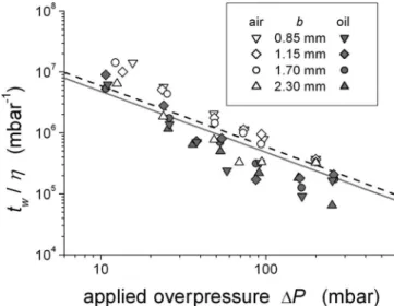
The waiting time denoted twis defined as the time elapsed
from the moment when grain motion is first observed at the outer boundary until a propagating finger structure is initi-ated at the inner boundary. It is the typical time for the de-compaction front to move over the whole system length L0. Since the decompaction process is a direct result of the drag force exerted on the particles, the fluidization process is ex-pected to occur after shorter tw with increasing⌬P. This is
indeed confirmed in Fig. 5. On the other hand, there is no clear dependence on the cell thickness b, except for the air-grain system where the experiments performed with b = 2.3 mm distinguish themselves. In this case, the difference might be attributed to the role of gravity and decreased role of friction as one crosses over to a more three-dimensional
packing 共b=2.3 mm⬃29 particle diameters兲. This is not an issue in the oil-grain system since we have an isodense sus-pension.
By recognizing two zones with distinguishable solid frac-tions, we construct a simple analytical model for the waiting time, mainly based on mass conservation. For simplicity, we consider a one-dimensional model in the sense that the de-compaction front is flat and uniform over the cell width, and perpendicular to the sidewalls 共see Fig. 6兲. With the inner
boundary defined as X = 0, the initial condition is Xg共t=0兲
= Xdec共t=0兲=L0. Here Xgis the position of the outer
bound-ary, Xdecis the position of the decompaction front, and L0 is the initial length of the packing. The length of the decom-paction zone at a time t is ldec共t兲=Xg共t兲−Xdec共t兲. At an
arbi-trary time t, conservation of mass and grains gives
0Xdec+decldec=0L0. 共1兲 Conservation of grain flux links the velocity of the outer boundary Vg= dXg/dt, and the velocity of the decompaction
front Vdec= dXdec/dt, through Vg=
冉
1 −0 dec
冊
Vdec. 共2兲
For the oil-grain case, the fluid velocity into the decom-pacted region equals the velocity of the outer boundary, and the Darcy law gives
Pi− Pdec Xdec
= 0
0共0兲Vg. 共3兲
Pi− Pdecis the pressure drop over the nondecompacted ma-terial, which acts as a fixed porous material with a Carman-Kozeny permeability0共0兲. Piis the injection pressure, and
Pdecis the pressure at the front positioned at Xdec. Similarly, over the decompacted region Darcy’s relation gives
Pdec− Patm ldec
= paste
HS共b兲Vg. 共4兲
Here the grains and the fluid are considered as an effective fluid with a viscositypaste, and the permeability is given by the confining space of the Hele-Shaw cell asHS共b兲=b2/12. We introduce “paste” as a common nomenclature for both the air-grain and the oil-grain systems, referring to the granu-lar material and the fluid flowing together.
The above flux conservation consideration is valid only if the fluid velocity is comparable to the velocity of the outer boundary. For the oil-grain system the fluid-air interface ad-jacent to the outlet is visually accessible, and the fluid flux is measurable. The velocity of the outer grain boundary, Vg, is
the same as the oil velocity Voil. Since the fluid is not visu-ally traceable and flux measurements not made available for the air-grain case, we estimate the fluid seepage velocity relative to the grains, Vflux, using the Darcy relation. At the instant just before forming a finger, the granular medium is decompacted over the whole system length. The Carman-Kozeny permeability is 共dec= 59%兲=7.0⫻10−12m2, and Vg is typically from 0.5 to 20 cm s−1 for the corresponding
FIG. 4. Typical experiments. Images in共a兲 and 共b兲 show the raw images for, respectively, air-grain and oil-grain mixtures, while in 共c兲 and共d兲 the corresponding subtracted and filtered images show the mobile zones. Air-grain system: b=1.15 mm, ⌬P=13 mbars. Oil-grain system: b = 1.15 mm,⌬P=11 mbars. The dashed vertical lines indicate the initial position of the outer grain boundary. The bar on the bottom displays the color code representing immobile zones with solid fraction0, mobile or decompacted zone with solid fractiondec⬍0, and the
Vflux Vg
=共/air兲 ⵜ P Vg
⬃ 0.43, 共5兲
the proposed model seems reasonable to use also for the air-grain system.
Combining Eqs.共3兲 and 共4兲, we obtain
Pi− P0 Vg =0 0 Xdec+ paste HS ldec. 共6兲 From Eq. 共1兲 we have ldec=0/dec共L0− Xdec兲, and by per-forming a substitution of Vgusing Eq.共2兲, Eq. 共6兲 yields
⌬P Vdec =
冉
1 −1 c冊
冋
paste HS 1 cL0+冉
0 0 −paste HS 1 c冊
Xdec册
, 共7兲 where c =dec/0. By using Vdec= dXdec/dt and integrating with the boundary conditions t = 0, Xd= L0, and t = tw, Xdec = 0, we obtain the time tw for the decompaction front totravel the length of the granular packing. In the framework of this model, the waiting time becomes
tw= 共1/c − 1兲L02 2⌬P
冉
paste HS 1 c+ 0 0冊
. 共8兲We now determine the quantities of the model: c is mea-sured experimentally as A0/A共t兲, and gets its value from Fig.
7 at the instant t = tw: cair⬃0.985 and coil⬃0.987. The
vis-cosity of the pure fluid 0 is 1.8⫻10−5Pa s for air and 5.0 ⫻10−3 Pa s for the silicone oil. The initial permeability is estimated using the Carman-Kozeny relation giving 0= 5.1 ⫻10−12m2at
0⬃62% for the air-grain system, and for the oil-grain system 0= 6.6⫻10−12m2 at 0⬃60%. Analo-gously to flow of a simple fluid in a Hele-Shaw cell, Darcy’s law is used in order to linkpaste/HSto the applied pressure gradient and the flow velocity, via the mobility Mpastedec :
Mpastedec = HS paste
= Vg
兩ⵜP兩, 共9兲
whereⵜP=⌬P/Xg共t兲 is the pressure gradient over the length
of the granular packing Xg共t=tw兲. Vg andⵜP are measured
independently for each experiment at the instant t = tw, which
is just on the verge of finger propagation, when the packing has been decompacted over the whole length L0. The paste mobility at tw is roughly 1.3⫻10−6 m2Pa−1s−1 for the
air-FIG. 5. Log-log representation of the waiting time twscaled with the fluid viscosity, as a function of the applied⌬P. The dashed line is the modeled waiting time for the air-grain system, and the solid line is the modeled waiting time for the oil-grain case.
FIG. 6. Scheme and quantities involved in the modeling of the decompaction process.
(a) (b)
FIG. 7. Temporal evolution of the average global solid fractions共t兲/0for共a兲 air-grain and 共b兲 oil-grains systems. Along the x axis the
grain system, and 2.8⫻10−9m2Pa−1s−1 for the oil-grain system.
The modeled waiting time scaled by the respective fluid viscosity is given in Fig. 5. Given the one-dimensional model, which represents a significant simplification of the observed decompaction front, and other simplifications like the assumed Darcy law for the mobile paste across the cell, the model compares favorably with the experiments. The 1/⌬P relation of modeled waiting time fits with the experi-mental data for the higher applied overpressures, while slightly deviating at lower pressures.
IV. “EMPTY” FINGER PROPAGATION
It is evident that the decompaction process prepares the medium for further channeling. The subsequent fingerlike structure empty of grains progresses preferentially in the zone that has been decompacted during the passage of the decompaction front. In this section we focus on the flow properties of the granular material and the finger structures developing after the unjamming process.
A. Image analysis and definition of the measured quantities In order to quantitatively compare the two systems we identify the measurements of interest, as given in Fig. 8. Great effort has been put into numerically processing the subsequent images as closely as possible, so as to extract time-dependent quantities that can be compared.
The driving force of the grain motion is the pressure gra-dient兩ⵜP兩. It can be estimated as the pressure difference over the extent of the paste, ⌬P/l共t兲, where l共t兲=Xg共t兲−Xf共t兲 is
the length of the paste ahead of the most advanced point of the finger. Xfis the linear extent of the finger, and Xgis the
position of the outer air-grain boundary. ⌬P is considered constant within the finger empty of grains. Due to a very high permeability contrast with that of the confined paste, the entire pressure drop is over the paste.
We take advantage of the mobility to characterize and quantify the coupled fluid-grain flow. In the same spirit as the definition of the paste mobility during the decompaction stage given in Eq.共9兲, the mobility during finger propagation
is
M =Vpaste
兩ⵜP兩. 共10兲
We adapt a common practice among similar studies and de-termine the mobility by measuring the velocity of the paste pushed ahead of the propagating finger as
Vpaste= 1 W
dAf共t兲
dt , 共11兲
where Af共t兲 is the area of the finger structure, and W is the
cell width. This definition of Vpastecomes from mass conser-vation and is effectively the same as Vf, where Vf is the
finger tip velocity, and=wf/W with wf as the average
fin-ger width. Note that, even though we are dealing with a miscible two-phase system, Eqs. 共10兲 and 共11兲 assume that
ⵜP is entirely driving the finger propagation, and seepage is negligible during this stage. We compare the typical veloci-ties of the fluid flux into the pore space of the granular ma-trix Vflux, and the finger tip velocity Vf. The permeabilityis
between 5.1 and 7.0⫻10−12m2, and V
f is typically
20– 50 cm s−1 for the air-grain and 0.1– 2 cm s−1 for the oil-grain system. Within the probed range of pressures, we find the fraction Vflux Vf =共/0兲 ⵜ P Vf 共12兲 to be less than 10% for the air-grain and less than 1% for the oil-grain system. This suggests that the velocity of the fluid flow on the pore scale is negligible compared to the finger velocity, but comparable to the grain velocity during finger propagation. ⵜP is thus mainly driving the finger and thus the paste, rather than contributing to seepage. This validates the use of Eqs.共10兲 and 共11兲.
As the patterns are relatively complex, we choose the definition for the individual finger width wi= 2A/s, where A
is the area occupied by the finger empty of grains divided by half of the perimeter s. We always consider the finger only over a distance of 6 cm共corresponding to the cell width W兲 measured from the finger tip. This approach of measuring the finger width corresponds to considering a single branched structure.
B. Flow properties
When the emptied finger propagates through the higher-permeability path prepared during the decompaction stage, the granular material is pushed in front of the finger tip. We use the mobility to characterize the flow properties and show to what extent the material is mobilized as a function of the applied overpressure⌬P and the cell thickness b.
Surprisingly, we find that, unlike flow of viscous fluids in Hele-Shaw cells and flow in porous media, the mobility is observed to be increasing during finger propagation, for a given experiment at constant ⌬P. The mobility is thus rep-resented as a function of this finger tip position Xf, for a
given b, and varying⌬P, as in Figs. 9共a兲and9共b兲.
The almost linearly increasing mobility observed for the air-grain system as well as for the oil-grain system, implies that the granular material is increasingly fluidized and flows more easily during the course of the experiment. We cannot at the moment precisely account for the evolution of the mobility, and despite the strong similarities observed in the two systems, this phenomenon might originate from different mechanisms.
For the air-grain case, the evolving mobility might be at-tributed to the continuous decompaction of the granular
ma-FIG. 8. Quantities measured during image analysis of the propa-gating fingers empty of grains.
terial during finger propagation, as shown in Fig. 10. The solid fraction of decompacted material versus the initial frac-tion seems to be independent of the applied⌬P. Note that in some cases it is not possible to reliably estimate the compac-tion index during finger propagacompac-tion for the air-grain system. For experiments performed with a large cell thickness b and a low⌬P, particles tend not to be as effectively transported along with the air flow within the finger. In this case, grains sediment on the bottom plate inside the finger in layers a few particle diameters deep. The depth of these layers is expected to be some function of ⌬P, but this piece of information is not accessible for these experiments. For the results shown in Fig.10for b = 1.15 mm, only experiments where the fingers are completely empty of grains are included. For the oil-grain case, since it is an isodense suspension, such gravity effects are not an issue.
The fact that change in the initial packing density strongly alters the behavior of the mobility is a piece of evidence supporting a relation between the increasing mobility and an
overall decreasing compaction by fluidization during the fin-ger growth. At ⬃62% initial packing fraction, the granular material is far beyond the jamming transition. It takes time to reach a completely unjammed state. If, however, the granular material is already initially close to the jamming transition, as for the samples produced for the air-grain case with a packing fraction⬃56%, the paste flows readily as an effec-tive fluid. The mobility is roughly constant during the pro-gression of the finger关see insets in Figs.9共a兲and9共c兲兴.
The decompaction during finger propagation is rather modest for the oil-grain experiments, and mainly localized around finger tip positions Xf⬍1 cm 关see Fig.10共a兲兴. This
suggests that the decompaction alone cannot explain the in-creasing mobility. In this case, lubrication effects due to re-structuring in terms of particle migration 关44兴 toward the
center of the cell gap might be an important factor.
For both systems, the mobilities are found to be indepen-dent of the applied⌬P. Hence, we average over all the ex-perimental runs with variable⌬P, for the various cell
thick-FIG. 9. Mobility M as a function of finger tip position Xffor共a兲 air-grain and 共b兲 oil-grain systems. The cell thickness b=1.15 mm. 共c兲
and共d兲 show the rescaled mobility M*= M/共d2/兲 as a function of finger tip position for air-grain and oil-grain systems, respectively. The
rescaled mobility is averaged over all⌬P for each given b. Approximately 27 trials are used for the air-grain experiments and seven for the oil-grain case. The insets similarly show M and M*obtained for the experiments involving an initially loosely packed granular matrix.
nesses b. To be able to compare the magnitude of these averaged mobilities between the two systems, we scale M with d2/, which is the typical mobility for flow of a fluid of viscosity through a pore of size d. This defines M*
= M/共d2/兲, where d is the diameter of the grains, andthe viscosity of the pure fluid共oil or air兲. M*is plotted as func-tion of the finger tip posifunc-tion in Figs.9共c兲and9共d兲, display-ing, respectively, the air-grain and oil-grain experiments. We find that the mobilities compare favorably—they are roughly of the same order of magnitude for the two systems. For both air-grain and oil-grain experiments, there is a noticeable ef-fect on the mobility from varying b. There is a tendency of a higher mobilization rate for larger b, given the increasing slopes from small to large b. During finger propagation the mobilities seem to saturate, indicating that there might be a transition to a steady state of the paste flow, characterized by a constant mobility at a given b. The experiments performed at an initially lower packing fraction and close to the jam-ming transition indeed show the existence of such a state 关see inset in Fig. 9共c兲兴. To further investigate the transition
from a regime where the mobility is evolving with the finger tip position to a stationary flow regime, a longer sample would be required.
For the air-grain system, the overall higher mobility for increasing cell thickness b might be attributed to less effec-tive friction between the fluidized granular material and its confining walls as b is made larger, by considering friction mobilization in terms of a Janssen type of stress distribution 关45兴. If indeed lubrication is a key component in explaining
the positively evolving mobility, the friction argument fails for the oil-grain situation.
We know from other Hele-Shaw types of studies involv-ing viscous fluids that the mobility behaves as a quadratic function of the cell thickness b. For flow through a porous medium the mobility is independent of b. Given the geom-etry and aspect ratio of our experiments, we are not able to distinguish a coherent relation with respect to this parameter.
C. Finger widths
By direct visual comparison, the propagating fingers are found to appear wider for the air-grain system. Tip splitting
is more evident for the oil-grain experiments, and common for smaller cell thickness. Typical finger structures are shown in the left column in Fig.11.
We characterize the observed patterns in terms of the in-dividual finger width wias defined in Sec. IV A. For all the
probed ⌬P and cell thicknesses b, there is a weak linear increase of the individual finger width as function of the finger tip position, for both the air-grain and the oil-grain systems. We use this feature to obtain an average individual finger width. For a given ⌬P and b, the averaging is per-formed for finger widths corresponding to finger tip positions within the interval 8⬍Xf⬍17 cm.
A striking difference is observed when applying the two different fluids: for the air-grain case the finger width is a slightly increasing function of⌬P, as shown in Fig.11共b兲. In this case, the width is nonsensitive to variation of the cell thickness b. On the contrary, for the oil-grain system, the finger width is observed to be independent of ⌬P and thus independent of the finger velocity. However, for the oil-grain system the finger width is a function of b 关see Fig. 11共d兲兴. Thus, the main parameter defining the finger width is the applied overpressure ⌬P for the air-grain case, whereas for the oil-grain situation the cell thickness b selects the finger width.
V. CONCLUSION
We have presented an experimental study of two cases concerning fluid injection into a granular medium saturated by the same fluid as the injected phase. The two systems have been described phenomenologically and quantitatively within the parameter space of the applied fluid overpressure ⌬P and the thickness of the granular phase b.
The basic mechanism of fluidization is the same for the two cases. Since the granular packing is in a dense initial state, close to the random close packed configuration, the system is completely jammed. In order to transport grains, the packing must first dilate. Dilation is observed starting at the outer boundary facing the outlet. This dilation is referred to in terms of decompaction in the sense that we are able to
(a) (b)
FIG. 10. Evolution of the compaction index 关comparing average solid fractions,共t兲/0= A0/A共t兲兴 during finger propagation for 共a兲
distinguish a zone with⬃3% decrease in solid fraction com-pared to the initial one. This decompaction zone evolves in time, propagating in the opposite direction of the effective fluid flow. During the passing of the decompaction front the granular packing is successively unjammed. In this way, the decompaction prepares the system for a very effective fluid and grain transport. When the decompaction front has reached the inner boundary, a localized zone characterized by a higher permeability connects the inlet side directly to the outlet side of the packing. Within this zone the particles are effectively transported along with the fluid, giving room for a fingerlike pattern emptied of grains to propagate through the decompacted medium.
Information on the unjamming decompaction process is retrieved by using an image subtraction technique, from which the temporal evolution of the decompaction area is found. The area measurements provide information on the average solid fraction of the decompacted region, which can be exploited to model the observed waiting time. The waiting time is the time it takes for the decompaction front to travel over the whole system length—hence representing the
dura-tion for localized unjamming to occur over the entire length of the granular packing. The modeled waiting time compares favorably to both the respective experimental data sets. The waiting time found experimentally for the two systems com-pares very well when scaled with their fluid viscosity.
The emerging fingerlike patterns following the unjam-ming process of the granular phase are quite similar between the two systems. Geometrically, these fingers are quantified through their width. In both systems a slight widening of the fingers is observed during finger propagation. A striking dif-ference on the finger width is observed as a result of injec-tion of two different fluids. When the injecinjec-tion is made with air, the finger width is increasing as a function of ⌬P, but does not respond to varying the cell thickness b. However, when oil is injected into the oil-grain system the finger width is no longer a function of ⌬P but increases instead with b. Furthermore, the fingers are typically wider in the air-grain case.
The fluidization process during finger propagation is de-scribed in terms of the mobility. Contrary to the constant mobilities measured in Hele-Shaw systems with strong
FIG. 11. 共a兲, 共c兲. Typical Patterns, respectively, for air-grain and oil-grain systems: for the presentation of air-grain results b=1.15 mm and⌬P is varied. For oil-grain systems the experiments are presented at a fixed ⌬P⬃55 mbars but at different b. Right panels: Averaged individual finger width wi, scaled on the cell width W for共b兲 air-grain and 共d兲 oil-grain systems. For the air-grain system, wi/W is a function of⌬P. Each point represents an average over roughly 27 experiments. For the oil-grain system, wi/W is a function of b.
analogies with the present study, i.e., two-fluid viscous fin-gering or fluid flow in fixed porous media, the mobility is increasing during finger propagation. This is the signature of a continuously more effective particle transport that might be attributed to a decreasing solid fraction during finger propa-gation, and perhaps also migration of the suspended particles toward the center of the cell gap in the oil-grain case. The mobilities of the two systems are of the same magnitude when scaled with respect to the fluid viscosity. For both sys-tems the mobility of the flowing fluid-grain mixture is an increasing function of the cell thickness.
Evidently, experiments performed 共air-grain system兲 at different initial packing fractions manifests the initial pack-ing fraction as a crucial parameter for the overall dynamic
behavior of the system. An initially loose granular matrix flows more like an effective fluid through the entire course of the experiment, recognized by a constant mobility during finger propagation. Prospected studies with a longer linear cell might reveal a transition from a regime characterized by an evolving mobility to such a stationary regime for the ini-tially denser system.
ACKNOWLEDGMENTS
This work was supported by the Norwegian Research Council 共NFR兲, CNRS through a PICS grant, and ANR through the ECOUPREF and TRIGGERLAND grants.
关1兴 H. S. Hele-Shaw, Nature 共London兲 58, 34 共1898兲.
关2兴 P. G. Saffman and G. I. Taylor, in Proc. R. Soc. London, Ser. A
245, 312共1958兲.
关3兴 D. Bensimon, L. P. Kadanoff, S. Liang, B. I. Shraiman, and C. Tang, Rev. Mod. Phys. 58, 977共1986兲.
关4兴 R. L. Chuoke, P. van Meurs, and C. van der Poel, Trans. Met-all. Soc. AIME 216, 188共1959兲.
关5兴 J. V. Maher, Phys. Rev. Lett. 54, 1498 共1985兲.
关6兴 D. Bonn, H. Kellay, M. Ben Amar, and J. Meunier, Phys. Rev. Lett. 75, 2132共1995兲.
关7兴 G. Daccord, J. Nittmann, and H. E. Stanley, Phys. Rev. Lett.
56, 336共1986兲.
关8兴 J. Nittman, G. Daccord, and H. E. Stanley, Nature 共London兲
314, 141共1985兲.
关9兴 A. Lindner, P. Coussot, and D. Bonn, Phys. Rev. Lett. 85, 314 共2000兲.
关10兴 A. Lindner, D. Bonn, E. C. Poiré, M. Ben Amar, and J. Meu-nier, J. Fluid Mech. 462, 237共2002兲.
关11兴 C. Chevalier, A. Lindner, and E. Clement, Phys. Rev. Lett. 99, 174501共2007兲.
关12兴 H. Darcy, Les Fontaines Publiques de la Ville de Dijon 共Dal-mont, Paris, 1856兲.
关13兴 M. E. Cates, J. P. Wittmer, J.-P. Bouchaud, and P. Claudin, Phys. Rev. Lett. 81, 1841共1998兲.
关14兴 A. L. Liu and S. Nagel, Nature 共London兲 396, 21 共1998兲. 关15兴 C. S. O’Hern, L. E. Silbert, A. J. Liu, and S. R. Nagel, Phys.
Rev. E 68, 011306共2003兲.
关16兴 T. S. Majmudar, M. Sperl, S. Luding, and R. P. Behringer, Phys. Rev. Lett. 98, 058001共2007兲.
关17兴 S. F. Pinto, M. S. Couto, A. P. F. Atman, S. G. Alves, A. T. Bernardes, H. F. V. de Resende, and E. C. Souza, Phys. Rev. Lett. 99, 068001共2007兲.
关18兴 K. Lu, E. E. Brodsky, and H. P. Kavehpour, Nat. Phys. 4, 404 共2008兲.
关19兴 Ø. Johnsen, R. Toussaint, K. J. Måløy, and E. G. Flekkøy, Phys. Rev. E 74, 011301共2006兲.
关20兴 Ø. Johnsen, R. Toussaint, K. J. Måløy, E. G. Flekkøy, and J. Schmittbuhl, Phys. Rev. E 77, 011301共2008兲.
关21兴 C. Chevalier, A. Lindner, M. Leroux, and E. Clément, J. Non-Newtonian Fluid Mech. 共2008兲 doi: 10.1016/ j.jnnfm.2008.07.007共to be published兲.
关22兴 P. Mills, P. Cerasi, and S. Fautrat, Europhys. Lett. 29, 215 共1995兲.
关23兴 P. Cerasi and P. Mills, Phys. Rev. E 58, 6051 共1998兲. 关24兴 E. Lemaire, Y. O. M. Abdelhaye, J. Larue, R. Benoit, P. Levitz,
and H. V. Damme, Fractals 1, 968共1993兲.
关25兴 X. Cheng, L. Xu, A. Patterson, H. M. Jaeger, and S. R. Nagel, Nat. Phys. 4, 234共2008兲.
关26兴 J. L. Vinningland, Ø. Johnsen, E. G. Flekkøy, R. Toussaint, and K. J. Måløy, Phys. Rev. E 76, 051306共2007兲.
关27兴 J. L. Vinningland, Ø. Johnsen, E. G. Flekkøy, R. Toussaint, and K. J. Måløy, Phys. Rev. Lett. 99, 048001共2007兲. 关28兴 E. G. Flekkøy, S. McNamara, K. J. Måløy, and D. Gendron,
Phys. Rev. Lett. 87, 134302共2001兲.
关29兴 D.-V. Anghel, M. Strauss, E. G. Flekkøy, S. McNamara, and K. J. Måløy, Phys. Rev. Lett. 97, 059902共E兲 共2006兲. 关30兴 X.-l. Wu, K. J. Måløy, A. Hansen, M. Ammi, and D. Bideau,
Phys. Rev. Lett. 71, 1363共1993兲.
关31兴 D. Gidaspow, Multiphase Flow and Fluidization 共Academic Press, San Diego, CA, 1994兲.
关32兴 J. F. Davidson, Bubbles in Fluidized Beds 共Kluwer Academic, New York, 1995兲, p. 197.
关33兴 J. F. Davidson and D. Harrison, Fluidization 共Academic Press, New York, 1971兲.
关34兴 K. S. Lim, J. X. Zhu, and J. R. Grace, Int. J. Multiphase Flow
21, 141共1995兲.
关35兴 C. Zeilstra, M. A. van der Hoef, and J. A. M. Kuipers, Phys. Rev. E 74, 010302共R兲 共2006兲.
关36兴 D. Lohse, R. Bergmann, R. Mikkelsen, C. Zeilstra, D. van der Meer, M. Versluis, K. van der Weele, M. van der Hoef, and H. Kuipers, Phys. Rev. Lett. 93, 198003共2004兲.
关37兴 D. Lohse, R. Rauhé, R. Bergmann, and D. van der Meer, Na-ture共London兲 432, 689 共2004兲.
关38兴 C. F. Wan and R. Fell, J. Geotech. Geoenviron. Eng. 130, 373 共2004兲.
关39兴 T. W. J. V. Asch, J. Buma, and L. P. H. V. Beek, Geomorphol-ogy 30, 25共1999兲.
关40兴 T. Uchida, K. Kosugi, and T. Mizuyama, Hydrolog. Process.
15, 2151共2001兲, and references therein.
关41兴 D. Karátson, J.-C. Thouret, I. Moriya, and A. Lomoschitz, Bull. Volcanol.共Heidelberg兲 61, 174 共1999兲.
关42兴 G. D. Scott, Nature 共London兲 188, 908 共1960兲. 关43兴 P. C. Carman, Trans. Inst. Chem. Eng. 15, 150 共1937兲. 关44兴 D. Leighton and A. Acrivos, J. Fluid Mech. 181, 415 共1987兲. 关45兴 H. A. Janssen, Z. Ver. Dtsch. Ing. 39, 1045 共1892兲.