HAL Id: hal-01937586
https://hal.archives-ouvertes.fr/hal-01937586
Submitted on 5 Dec 2018
HAL is a multi-disciplinary open access
archive for the deposit and dissemination of
sci-entific research documents, whether they are
pub-lished or not. The documents may come from
teaching and research institutions in France or
abroad, or from public or private research centers.
L’archive ouverte pluridisciplinaire HAL, est
destinée au dépôt et à la diffusion de documents
scientifiques de niveau recherche, publiés ou non,
émanant des établissements d’enseignement et de
recherche français ou étrangers, des laboratoires
publics ou privés.
Pentagonal oxide DyMn2O5
S. Chattopadhyay, S. Petit, E. Ressouche, S. Raymond, V. Balédent, G.
Yahia, W. Peng, J. Robert, Marie-Bernadette Lepetit, M. Greenblatt, et al.
To cite this version:
S. Chattopadhyay, S. Petit, E. Ressouche, S. Raymond, V. Balédent, et al.. 3d-4f coupling and
multiferroicity in frustrated Cairo Pentagonal oxide DyMn2O5. Scientific Reports, Nature Publishing
Group, 2017, 7, pp.14506. �10.1038/s41598-017-15150-w�. �hal-01937586�
www.nature.com/scientificreports
3d-4f coupling and multiferroicity in
frustrated Cairo Pentagonal oxide
DyMn
2
O
5
S. Chattopadhyay
1, S. Petit
2, E. Ressouche
1, S. Raymond
1, V. Balédent
3, G. Yahia
3, W. Peng
3,
J. Robert
4, M.-B. Lepetit
4, M. Greenblatt
5& P. Foury-Leylekian
3In solid state science, multifunctional materials and especially multiferroics have attracted a great deal of attention, as they open the possibility for next generation spintronic and data storage devices. Interestingly, while many of them host coexisting 3d and 4f elements, the role of the coupling between these two magnetic entities has remained elusive. By means of single crystal neutron diffraction and inelastic neutron scattering experiments we shed light on this issue in the particular case of the multiferroic oxide DyMn2O5. This compound undergoes a first order magnetic transition from a high
temperature incommensurate phase to a low temperature commensurate one. Our investigation reveals that although these two phases have very different magnetic structures, the spin excitations are quite similar indicating a fragile low temperature ground state with respect to the high temperature one. Such a rare scenario is argued to be a manifestation of the competition between the exchange interaction and 4f magnetic anisotropy present in the system. It is concluded that the magnetic structure, hence the ferroelectricity, can be finely tuned depending on the anisotropy of the rare earth.
Magnetic ferroelectrics, where the onset of ferroelectricity essentially requires the spins to be ordered, are a fasci-nating class of materials1. The associated physics is undoubtedly challenging because of the coupled spin, charge,
and lattice degrees of freedom. Particularly, the issue of determining the actual role of spin in the emergence of ferroelectric state has been a very crucial topic of research in recent years. Different mechanisms have been pro-posed, like the inverse Dzyaloshinskii-Moriya (DM) interaction model2, the exchange-striction mechanism1 and
the spin dependent metal-ligand hybridization model3–6 among others, but no universal model could be
imple-mented to the entire family. It remains that the magnetic properties of many of such magnetic ferroelectrics are driven by 4f rare earths and 3d transition metal ions. There is thus some urgency in understanding the role of the 3d-4f coupling. Noting the fact that 4f elements are also well known for their exotic electric properties, for their usage in various laser based applications and also as permanent magnets (NdFeB and SmCo for instance), understanding the coupling between the two magnetic species would significantly benefit the wing of material engineering as far as the technological implementation is concerned.
In this report, we have chosen to study DyMn2O5, a spin induced multiferroic system of the RMn2O5 (R = Y,
Rare earths) family showing large spontaneous electric polarization and colossal magnetoelectric effect, one of the strongests in the entire family1,7–14. With the coexistence of 4f and 3d metals, this composition appears to be
an ideal seedbed to investigate the 3d-4f coupling in a very prominent way.
DyMn2O5 is mainly characterized by two transitions. Below T1 = 42 K, it undergoes a magnetic phase (HT
phase) transition with a propagation vector k1 = (1/2 − δ(T), 0, 1/4 − ε(T))12,15. Ferroelectric order arises below
40 K which is very close to the HT transition. With lowering temperature, a first order phase transition occurs at
T2 = 8 K, from the HT phase to a low temperature commensurate magnetic phase (LT) with k2 = (1/2, 0, 0). This
transition is believed to be associated with the ordering of Dy3+ moments. In few literatures, the existence of a lock in transition around 18 K was also reported12. Although very weak, the HT phase persists below T
2 and coexists
with the LT phase. In spite of a few previous attempts, revealing the magnetic structures of different phases has
1INAC-MEM, CEA-Grenoble and Université Grenoble Alpes, F-38000, Grenoble, France. 2Laboratoire Léon Brillouin, CEA, CNRS, Université Paris-Saclay, CE-Saclay, F-91191, Gif-sur-Yvette, Cedex, France. 3Laboratoire de Physique des Solides, CNRS, Université Paris-Sud, Université Paris-Saclay, 91405, Orsay, cedex, France. 4Institut Néel, CNRS and Université Grenoble Alpes, 38042, Grenoble, cedex 9, France. 5Department of Chemistry and Chemical Biology, Rutgers, the State University of New Jersey, Piscataway, NJ, 08854, USA. Correspondence and requests for materials should be addressed to S.C. (email: [email protected])
Received: 28 July 2017 Accepted: 16 October 2017 Published: xx xx xxxx
remained a dubious issue for this compound12,15–17. In this study, we conclusively determine the magnetic
struc-ture of both the HT and LT phases, by means of detail single crystal neutron diffraction experiments. In addition, inelastic neutron scattering investigations were carried out to characterize the spin dynamics. It is found that the spin excitations of the HT and LT phases are surprisingly very similar, showing especially a soft mode along (3/2, 0, ).
As claimed in a recent study, DyMn2O5 belongs to ferroelectric Pm group18 but only differs from the Pbam
orthorhombic space group by weak deformations. DyMn2O5 is formed by Mn3+O5 square pyramids and corner
sharing Mn4+O
6 octahedra8,9. In the (a, b) plane, loops of five Mn ions (three Mn3+ and two Mn4+) are formed
with three inequivalent nearest neighbor antiferromagnetic (AFM) interactions: J3, and J4 couple the Mn3+ and
Mn4+ ions while J
5 couples the Mn3+ (see Fig. 1a). In contrast, along c, ribbons of Mn4+ are formed in presence
of J1 (via Dy3+ layers) and J2 (via Mn3+ layers) interactions, as shown in Fig. 1b. Interestingly, the magnetic
frus-tration inherent to all multiferroic materials is here due to the “Cairo pentagonal lattice” formed by Mn3+ and
Mn4+ ions (see Fig. 1d and ref.19). Such lattices have become famous in the problem of tiling a plane with regular
polygons, but also after the beautiful streets in the city of Cairo paved in this design.
Results
Solving the magnetic structures: LT and HT phases.
We performed single crystal neutron diffraction operated in four circles geometry using a crystal with size nearly 2.5 × 1.7 × 1 mm3. About 400 to 500 nuclear and/or magnetic Bragg reflection’s integrated intensities were estimated at 50 K, 25 K, 15 K, and 2 K by measuring rock-ing curves around each reflections. Figure 2 shows a few representative rocking curves fitted with Gaussian func-tion. The curves presented could be categorized into three distinct groups: (a)–(c) nuclear reflections, (d)–(f) LT phase magnetic reflections, and (g)–(i) HT phase magnetic reflections. From the fit it is evident that the nuclear and magnetic reflections with nearly equal ω values have practically identical peak widths as expected for long range magnetic order. The refinement of the angular positions of the 50 K (above the magnetic transition) nuclear reflections revealed that the lattice constants are quite close to the one reported at room temperature. These values also match well with the literature reported earlier using powder sample15. Refinements of the nuclear and
mag-netic structures at 2 K and 15 K were performed using the FullProf software package20. We used the formalism of
Becker-Coppens to refine the extinction in the crystal. The pretty low values of the discrepancy factors ensure the quality of the refinement we achieved. The scale factors obtained from the refinements were used in the refine-ments of the magnetic structures at 15 K and 2 K.
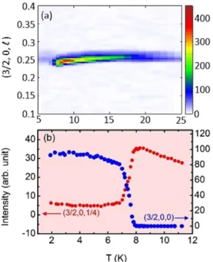
To follow the temperature evolution of the magnetic propagation vectors, Q-scans were performed below 45 K. The satellites are only visible below 30 K due to a large background. Two magnetic phases are observed, in agree-ment with previous reports: above 8 K, an incommensurate phase (HT) with k1 = (1/2 − δ(T), 0, 1/4 − ε(T)) with δ(T) and ε(T) being very small and, below 8 K, a commensurate phase (LT) with propagation vector k2 = (1/2, 0,
0). Figure 3(a) shows Q-scans carried out along (3/2, 0, ) for a series of temperatures in a color-map fashion.
ε(T) increases slightly up to 8 K where the HT-LT transition occurs. Although very weak, the signal of the HT phase persists down to 2 K (in agreement with previous reports)15. Figure 3(b) shows the thermal variation of two
Figure 1. (a) A perspective view of the crystallographic structure and the Mn-Mn magnetic exchange
interactions in the (a, b) plane for DyMn2O5. (b) The Mn4+ chain along c and the dominant Mn-Mn exchange
interactions in the (a, c) plane. It also shows Mn3+-Dy3+ interaction J
6 along c. (c) Detailed path of interaction
www.nature.com/scientificreports/
specific magnetic Bragg reflections (3/2, 0, 1/4) and (3/2, 0, 0), characteristics of the HT and LT phases respec-tively. It clearly shows that the (3/2, 0, 1/4) reflection becomes extremely weak in comparison with the (3/2, 0, 0) that rises below 8 K. We thus confirm that the magnetic ground state of this compound consists of two coexisting phases: the dominant LT phase along with the very feeble HT phase.
At 2 K, 500 magnetic Bragg reflections were collected associated with the propagation wave vector k2 = (1/2,
0, 0). Unfortunately, representation analysis was not of any use to find symmetry relations among moments and thus determine a model of the magnetic structure. Refinement of the LT phase turned out to be challenging in presence of ten uncorrelated magnetic sites corresponding to three magnetic sub-lattices (Dy3+ Mn3+ and Mn4+).
It was found that using a toy model with magnetic symmetry P2ab′21m′ helped to reduce the free parameters in
some of the RMn2O5 systems with (1/2, 0, kz) propagation vector15,21. This magnetic space group is a derivative of
the crystallographic group Pb21m which was proposed to be the space group in the emerged ferroelectric phase of
RMn2O5 at low temperature8. We started the refinement using this model. To make the scenario simpler, we also
incorporated few constraints based on literature available for RMn2O515,21. These constraints included working
with a spin density wave (SDW) model, putting all the spins in the (a, b) plain. In addition, moments of similar type of ions were set to be equal. Testing with different possible orientations among the spins under the constraint relations mentioned above eventually steered us to the solution of the magnetic structure depicted in Fig. 4(a) and in Table 1. A very good agreement factor (RF = 8.6%) ensures that the proposed model is reliable. The spins are Figure 2. Some of the representative rocking curves from the single crystal neutron diffraction experiment.
(a–c) Nuclear reflections measured at 50 K, (d–f) magnetic reflections corresponding to the LT phase measured at 2 K, and (g–i) magnetic reflections corresponding to the HT phase measured at 15 K. Solid lines are fit to the curves with a Gaussian function. The estimated full width at half maximum (FWHM) is also shown for each measured reflection.
found predominantly along the b direction, and arranged in a ferromagnetic fashion along the c axis (see also the focus in Fig. 5(a). The non collinearity within the (a, b) plane is the manifestation of the different frustrated inter-actions. The obtained structure is close to the one reported by Blake et al. using powder neutron diffraction data15.
Figure 3. (a) A color map constructed by combining the Q-scans along (1 5, 0, ). with varied temperature. Thermal dependence of integrated intensities for two magnetic satellites (b) (3/2, 0, 1/4) and (3/2, 0, 0) across the transition at 8 K.
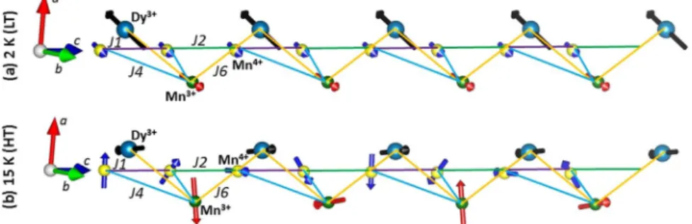
Figure 4. (a) Magnetic structure in the LT phase at 2 K where each sublattice is ferromagnetically stacked along c direction. (b) Magnetic structure of the HT phase refined at 15 K showing the spiral arrangement of Mn3+ and
Mn4+ spins along c. Spins of Dy3+ show up-up-down-down amplitude modulated structure along c. Magnetic
interactions J3, J4, and J5 are also shown. (c) Fobserved2 vs. Fcalculated2 plot for both temperatures to depict the quality
www.nature.com/scientificreports/
Similar to the situation observed in the LT phase, irreducible representation analysis with propagation vector
q = (0.5, 0, 0.25) was not useful due to the lack of correlations among the moments. Attempting the LT phase
structure in the 15 K (HT phase) data was unsuccessful. The model proposed by Wilkinson et al. corresponding to k2 reflections at 4 K did not appear to be suitable as well16. Unlike the situation at 2 K, usage of SDW
configura-tion under Shubnikov group P2ab′21m′ was a failure too, despite its flexibility. However, execution of simulated
annealing (SA) analysis helped to have some ideas about the nature of possible couplings with an indication of spirality in the Mn sublattices. Based on that, tests with numerous numbers of possible configurations were made. Such an attempt revealed that incorporating spiral structure descriptions for Mn3+ and Mn4+ sub-lattices along c
direction indeed improves the data fitting quality significantly. This spiral arrangement is described by the classi-cal Fourier decomposition: S 1(R iI e ) i
2 2
= + . − .π ψ where R and I are real and imaginary components respec-tively. ψ is a relative phase factor applicable to each site. We have used spherical polar coordinate system to represent the components of R and I (hence represented as (MR, θR, φR) and (MI, θI, φI) where M, θ, φ denote the
amplitude, polar angle, and azimuthal angle respectively).
However, usage of a spiral model for Dy3+ sublattice deteriorates the quality of fitting. Instead, inclusion of
Dy3+ spins following SDW approach helps to improve the refinement quality further. It is worth noting that such
states where the amplitude of the rare earth ordered magnetic moment is modulated, is a common feature in the RMn2O5 family7. The refined structure at 15 K is shown in Fig. 4(b) and the values of the refined parameters are
given in Table 2. The higher value of the RF (15.7%) factor is a manifestation of much weaker reflections at 15 K.
However, the Fobserved2 vs. Fcalculated2 plot strongly advocates for the satisfactory quality of the refinement (Fig. 4(c)).
Two magnetic domains, respectively generated by the (x, y, z) and (−x, −y, z) symmetry operations, have been taken into account, and their volume fraction was refined to 52/48%. Note that δ and ε are neglected in this approach. The obtained structure differs from two of the possible models made by Johnstone et al. using resonant x-ray technique at 15 K, since there is no spiral description in their proposition17. It is also different from the
model proposed by Ratcliff et al. at 22 K where only the Mn4+ spins show a spiral arrangement12. It is important
to mention that attempts of using these previously proposed models were unsuccessful.
Atom Position MR (μB) φ(°) θ(°) Phase (2π)
Mn3+ (0.4112, 0.3507, 0.5) 2.97(11) 105(3) 90 0 (0.5888, 0.6493, 0.5) 2.97(11) 285(3) 90 0 (0.0888, 0.8507, 0.5) 2.97(11) −22(4) 90 0 (0.9112, 0.1493, 0.5) 2.97(11) −22(4) 90 0 Mn4+ (0, 0.5, 0.2536) 1.88(5) 253(5) 90 0 (0, 0.5, 0.7465) 1.88(5) 253(5) 90 0 (0.5, 0, 0.2536) 1.88(5) 115(1) 90 0 (0.5, 0, 0.7465) 1.88(5) 115(1) 90 0 Dy3+ (0.1387, 0.1719, 0) 7.47(3) 295(1) 90 0 (0.3613, 0.6719, 0) 7.47(3) 115(1) 90 0 (0.6387, 0.3281, 0) 7.47(3) 295(1) 90 0 (0.8613, 0.8281, 0) 7.47(3) 295(1) 90 0
Table 1. Refinement result for the magnetic structure of DyMn2O5 in the LT phase at 2 K with k2 = (1/2, 0, 0).
The moments are described using spherical coordinates system with MR, θR, and φR being the real Fourier
components at the (x, y, z) positions, polar angle, and azimuthal angle respectively. The achieved agreement factor is RF = 8.6%.
Figure 5. Stacking of spins along c direction: (a) At 2 K (LT phase), all kinds of spins are parallel. (b) At
15 K (HT phase), spins of Mn4+ and Mn3+ show spiral arrangement. Mn4+ spins rotate by 45° from each site
to another along c whereas it is by 90° in case of Mn3+ . In contrary to the Mn spins, Dy3+ spins aquire an
amplitude modulated structure with ↑↑↓↓ fashion. In addition to the spin stacking, exchange interactions J2, J4,
Origin of the HT-LT transition: Numerical mean field calculation. With these results in hand, we now propose a
scenario to account for this sequence of magnetic structures. The main idea is that the Dy3+ spins are
character-ized by a strong easy-axis anisotropy that tends to align them along the b direction.
There are indeed some salient features which make the magnetic structure at 15 K rather different from the 2 K structure. At 2 K, all the spins are arranged ferromagnetically along the c direction, whereas, at 15 K, Mn4+ spins
rotate by 45° from site to site around the c axis, and by 90° in the case of Mn3+ ions. Interestingly, Dy3+ spins do
not prefer to be arranged in a spiral manner. The refined structure at 15 K corresponds to ↑↑↓↓ stacking along c of Dy3+ spins pointing along the b direction. This is a strong argument in favor of a significant anisotropy along
that particular axis. It is worth noting that thermal variation of magnetization measurement performed along the three crystallographic directions also indicates a slightly higher magnetization along b (not shown). To figure out quantitatively the nature of the Dy3+ anisotropy, numerical ab-initio calculations (including 4f electronic
correlation and spin-orbit interaction) have been performed, on an embedded DyO5 fragment. We used the
CASSCF code of the MOLCAS package22 for the orbital and correlation calculations, the EPCISO code23 for the
spin-orbit calculation and a home made code for the anisotropy and magnetic moments calculation from the
ab-initio results. We find that the low energy crystal field states of the Dy3+ ions are formed by a doublet. The
corresponding |↑〉 and |↓〉 states have an Ising like character and carry a moment μ = 〈↑|τ|↑〉 = −〈↓|τ|↓〉 = 8.5 μB
which forms an angle φ = 77° away from the a axis (hence close to the b axis). This compares very well with the experimental values of 7.5 μB and 115°. The |↑〉 and |↓〉 states are also well separated from the next excited states,
located at 16 meV.
Meanwhile, a closer look at the 2 K structure shows that Mn3+ and Dy3+ spins are anti-parallel to each other
along the c direction, suggesting that those spins are coupled by an AFM J6 interaction (see Fig. 5a). The proposed
scenario would then be the following: in the HT phase, the five Mn-Mn nearest neighbor interactions (J1 to J5)
stabilize a complex spiral arrangement of the Mn spins. Note that, according to literature, J5 is AFM and likely the
strongest interaction at play. Along J4 bonds, Mn4+ and Mn3+ are also anti-parallel to each other, suggesting that J3 is eventually the most frustrated coupling. Indeed, the effects of the different J3 on the magnetic energy cancel
each other for a Pbam space group. It results that J3 only acts through weak symmetry breaking, and thus its global
effect remains very small independently to its absolute value. The easy axis anisotropy of the Dy3+ spins competes
with this underlying spiral order and maintains the Dy3+ spins along b. To take advantage of J
6, however, the Dy3+
spins adopt this peculiar ↑↑↓↓ configuration. This is indeed a favorable compromise since for the sites where Mn3+ is along b, the J
6 exchange energy is fully satisfied, while for the sites where Mn3+ is along a, Dy3+ and Mn3+
spins are perpendicular, so that the J6 exchange energy is zero.
Mean field calculations are then carried out using the SpinWave software24 to determine the magnetic
struc-ture at a certain temperastruc-ture by means of energy minimization. The magnetic interactions at play are the J1,…,5
exchange couplings and the Mn3+-Dy3+ Ising coupling J
6. By studying rigorously over a wide range of values, it
was found that a parameter set corresponding to J1 = −1.5 meV, J2 = 1.5 meV, J3 = 0 meV, J4 = 1.75 meV, J5 = 3.5 meV and J6 = 0.03 meV could successfully yield a spiral magnetic structure similar to what is observed at
15 K with a propagation vector (1/2, 0, 1/4) (J3 cannot be evaluated due to cancellation effects by symmetry and
has thus be assigned to 0). This analysis leads to the following relation for the magnitude of the exchange param-eters: J5 ≥ J4 J3, which is in line with previous analysis25,26.
Although small, the inclusion of J6 is essential to stabilize the structure similar to the 15 K one. We propose
that since the ordered Dy3+ moment increases with decreasing temperature, the competition turns in favor of
the J6 exchange energy. It finally overcomes J1,2, destabilizes the spiral order, and results in a structure where all
Mn3+ and Dy3+ spins are anti-parallel. In this scenario, the magnetic phase transition is thus a manifestation of
the competition among the exchange interactions and the anisotropy energy.
Spin dynamics.
To further investigate this scenario, inelastic neutron scattering measurements have been carried out both in the HT and LT phases.Atom Position MR (μB) φR° θR° MI (μB) φI° θI° Phase (2π)
Mn3+ (0.4112, 0.3507, 0.5) 3.07(3) −194(2) 90 3.07(3) −104(2) 90 0 (0.5888, 0.6493, 0.5) 3.07(3) −14(2) 90 3.07(3) −284(2) 90 0 (0.0888, 0.8507, 0.5) 3.07(3) −159(2) 90 3.07(3) −69(2) 90 0 (0.9112, 0.1493, 0.5) 3.07(3) −159(2) 90 3.07(3) −69(2) 90 0 Mn4+ (0, 0.5, 0.2536) 2.33(2) −45(2) 90 2.33(2) −315(2) 90 0 (0, 0.5, 0.7465) 2.33(2) 0(2) 90 2.33(2) −270(2) 90 0 (0.5, 0, 0.2536) 2.33(2) −4(2) 90 2.33(2) −274(2) 90 0 (0.5, 0, 0.7465) 2.33(2) −319(2) 90 2.33(2) −229(2) 90 0 Dy3+ (0.1387, 0.1719, 0) 3.99(2) 115(1) 90 — — — 0.125 (0.3613, 0.6719, 0) 3.99(2) 79(1) 90 — — — 0.125 (0.6387, 0.3281, 0) 3.99(2) 259(1) 90 — — — 0.125 (0.8613, 0.8281, 0) 3.99(2) 115(1) 90 — — — 0.125
Table 2. Refinement results for the magnetic structure of DyMn2O5 in the HT phase at 15 K with k1 = (0.49, 0,
0.254). The spins have been described with their spherical coordinates (θ and φ). The spiral model encompasses a real (MR) and an imaginary (MI) Fourier component. The agreement factor is RF = 15.7%.
www.nature.com/scientificreports/
In standard magnets, an acoustic spin wave branch stems from the magnetic Bragg peak located at QBragg. This
branch corresponds to the long wavelength precession of the spins around the average local magnetization. With this picture in mind, the vicinity of the HT phase Bragg peak, QBragg = (3/2, 0, 1/4), has been mapped out as a function of
energy transfer ω and Q wave-vector. Because of the small size (~mm3) of the sample, successful executions of the
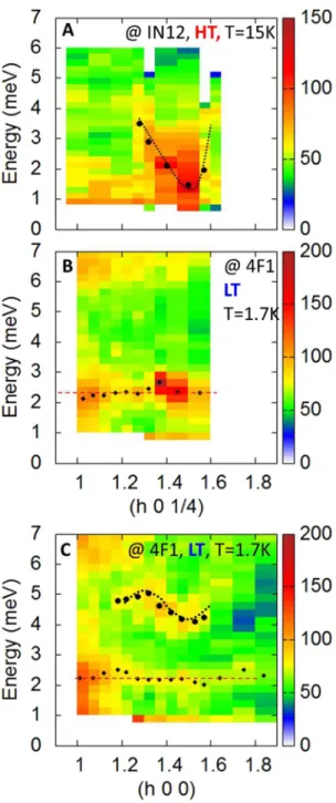
experiments were extremely challenging. All the measurements were thus repeated on different spectrometers (see Methods) to verify the genuineness of the data. Figures 6A and 7A display the neutron intensity measured at 15 K with Q along (3/2, 0, ), i.e. along c* and (h, 0, 1/4), i.e. along a* respectively (raw data). The directions of these two cuts in reciprocal space are depicted by dotted lines on the sketch presented in Fig. 6. Despite the weakness of the signal, different features can be noticed, which definitely resemble the spin wave response identified in the alike materials YMn2O525 and TbMn2O526. The data show indeed a feature (black dotted line) stemming from
≈ .
(3/2, 0, 0 35) and dispersing upwards both along and h. We note that this is a bit off from the Bragg position, expected at ≈ 1/4 . Furthermore, it is characterized by a gap Δ ≈ 1.5 meV. The branch also reaches a maximum around ħω = 4 meV at = 0, a behaviour again similar to that observed in YMn2O525 and TbMn2O526.
Figure 6B,C show the same data taken along c* in the LT phase at 2 K. Note that the wider range probed in C allows to demonstrate that the dispersion is symmetric with respect to =0, as it should be for a spin wave. Surprisingly, those maps look pretty similar to the one at 15 K. This is an intriguing property, since the minimum of the dispersion, at this temperature, is expected at (3/2, 0, 0), i.e. the Bragg peak of the LT phase, and not close to (3/2, 0, 1/4). Furthermore, the data provide evidence for an additional nearly flat mode around ħΩ = 2 meV. Along (h, 0, 1/4), see Fig. 7B, the acoustic spin wave is hard to detect, yet the intensity of the flat mode is strongly enhanced close to (3/2, 0, 1/4), as if the acoustic spin wave had collapsed on it. Along (h, 0, 0), however, the spin wave branch is again clearly visible in Fig. 7C, and corresponds to the upwards dispersion of the mode detected at 4 meV along c* (Fig. 6A–C) for = 0.
Such situations, where the acoustic spin wave branch does not stem from the Bragg peak of the magnetic structure, usually appear when exchange and anisotropy compete with each other, giving rise to “roton-like” min-ima in the dispersion27. Those minima appear at the Q
exch positions favored by exchange, yet the actual ground
state is characterized by Bragg peaks different from Qexch because of anisotropy. This is the case for instance in
metallic Dysprosium, where a strong anisotropy destabilizes the high temperature helicoidal phase to the benefit of a low temperature ferromagnetic one27. A large anisotropy spin gap opens at low temperature, yet the spin wave
branch continues to have minima at Q positions reminiscent of the helicoidal phase.
The inelastic neutron scattering experiments of Figs 6 and 7 integrate naturally in the scenario discussed above to account for the HT - LT transition. Indeed, the degeneracy of the ground doublet is lifted by the molecular field due to the Mn3+ spins, leading to a natural interpretation of the flat mode observed at Ω = 2 meV (see Fig. 7): the
latter simply identifies with the transition between the split |↑〉 and |↓〉 states. At the mean field level, the splitting Ω and the Dy3+ magnetization m could be written as:
μ Ω =zJ m g 2 J 6 Mn μ = Ω m k T tanh 2 B
where g = 2 is the 3d Landé factors, z = 2 is the number of Mn3+ neighbors of a given Dy3+ spin, and 〈m
Mn〉 ≈ 3 μB
is the average Mn3+ magnetic moment. From diffraction at 2 K, see Table 1, we measure μ ≈ 7.47 μ
B against 8.5 μB
according to the theory; at 15 K, Table 2 gives m = 3.99 μB against m = 4.8 μB using Ω ≈ 2 meV, hence a good
agreement. Finally, using Ω ≈ 2 meV, one gets J6 ≈ 0.06 meV. In the same spirit, we expect a modification of the
Mn4+-Mn3+ spin dynamics, i.e. a modification of the spin wave spectra. Actually, the exchange J
6 should, in
principle, hybridize the crystal field and spin wave responses, as for instance proposed in other materials like ErMnO36 or NdFe3(BO3)43. This hybridization may be the physical origin of the peculiar spectrum observed in
Fig. 7B, yet further theoretical studies are necessary to investigate this phenomenon.
Summary and Conclusion
The magnetic structure and the spin dynamics in the multiferroic oxide DyMn2O5 have been investigated by
means of neutron diffraction and inelastic scattering. A first order magnetic phase transition is reported at 8 K. It separates a high temperature magnetic structure spiraling around c direction with a propagation vector
≈
(1/2, 0, 1/4) and a low temperature antiferromagnetic configuration where spins are ferromagnetically stacked along c with a propagation vector (1/2, 0, 0). Although the high temperature phase persists to exist down to 2 K, the magnetic Bragg reflections become extremely weaker compared to the actual low temperature phase ones. Surprisingly, the nature of spin excitations is practically identical above and below the transition tempera-ture along c*. Based on both kinds of experiments, we propose that the physics at play is presumably associated to the competition between exchange interactions and the single ion anisotropy of the Dy3+ ion. More generally,
these findings demonstrate that the magnetic structure, hence the ferroelectricity, by virtue of the magneto-electric coupling, strongly depends on the anisotropy of the rare earth. The 3d-4f coupling thus appears as one of the key ingredients in the physics of multiferroics.
Methods Summary
Single crystals of DyMn2O5 were synthesized following the method described in ref.28. Single crystal neutron
diffraction experiments were conducted on the D23 diffractometer, a CEA-CRG instrument installed at the ILL (Grenoble, France). The instrument was operated in a four circles geometry with an incident wave length of
1.280(1) Å. The sample (2.5 × 1.7 × 1 mm3) was attached to the cold finger of a displex refrigerator. Its crystalline
quality was checked using the OrientExpress instrument installed at ILL.
Inelastic neutron scattering (INS) measurements were performed at the 4F and IN12 cold triple axes spectrometers installed at LLB and ILL respectively, on the very same crystal used for the diffraction measurements. The final wave vectors used were kf = 1.97 Å−1 and 1.8 Å−1 for 4F and IN12 respectively. To eliminate the higher order reflections, Figure 6. Inelastic neutron scattering measurements along c*. (A,B) Are cuts taken at 15 and 1.5 K respectively along (3/2, 0, ). (C) Shows the same data taken at the 4F1 spectrometer in a wider Q range. In (B,C), the diamonds show the fitted position of the nearly flat mode at Ω = 2 meV and the circles show the spin wave dispersion also fitted from the data. In these fits, we assumed a Gaussian profile. The dotted lines are guides to the eyes. The sketch depicts the (a*, c*) reciprocal plane along with the directions of the different cuts.
www.nature.com/scientificreports/
proper filtering was used. The sample was mounted to have access to Q=( , 0, ) scattering wave-vectors and h attached to the cold finger of an orange cryostat that can cool down to 1.7 K. Because of the small size (~mm3) of the
sample, INS experiments were extremely challenging. They were thus repeated on 4F and IN12 to verify the genuine-ness of the data. We then pursued the idea that features being common to the two sets of experiments should be retained only. It could be noticed, fortunately, that the spectra are close to each other, giving good confidence that the features, yet weak, are real. Furthermore, in the present manuscript, we chose to show the raw data; for instance, no background has been subtracted. To identify the signal, we compared the data with the spectra published for similar materials, YMn2O5 and TbMn2O5 in refs25 and26 respectively. Indeed, we observe features clearly reminiscent of the spin
wave branches reported in these two compounds. The spin wave energies were determined based on a simple fit assum-ing a standard Gaussian profile on top of a constant background. A flat feature at about 6.5 meV may also correspond to a signal (see 7B and C). Actuallly, owing to the experimental set up, this energy region corresponds to small scattering angles, hence a region where the contamination due to the incident beam may become significant especially when considering long counting times. The feature at 6.5 meV is likely due to this effect, and thus not relevant.
Figure 7. Inelastic neutron scattering measurements along a*. (A,B) Are cuts as a function of energy transfer and Q along (h, 0, 1/4) taken at 15 and 1.5 K respectively. (C) Shows a cut along (h, 0, 0) taken at low temperature. The diamonds highlight the flat mode at about Ω = 2 meV and the circles show the fitted spin wave dispersion. The dotted lines are guides to the eyes.
References
1. Cheong, S. W. & Mostovoy, M. Multiferroics: a magnetic twist for ferroelectricity. Nat. Mater. 6, 13–20 (2007).
2. Katsura, H., Nagaosa, N. & Balatsky, A. V. Spin current and magnetoelectric effect in noncollinear magnets. Phys. Rev. Lett. 95, 057205 (2005).
3. Hayashida, S. et al. Magnetic model in multiferroic NdFe3(BO3)4 investigated by inelastic neutron scattering. Phys. Rev. B 92, 054402
(2015).
4. Kang, T. D. et al. Coupling between magnon and ligand-field excitations in magnetoelectric Tb3Fe5O12 garnet. Phys. Rev. B 82,
014414 (2010).
5. Sirenko, A. A. et al. Infrared-active excitations related to Ho3+ ligand-field splitting at the commensurate-incommensurate magnetic
phase transition in HoMn2O5. Phys. Rev. B 78, 174405 (2008).
6. Chaix, L. et al. Magneto- to electroactive transmutation of spin waves in ErMnO3. Phys. Rev. Lett. 112, 137201 (2014).
7. Radaelli, P. G. & Chapon, L. C. A neutron diffraction study of RMn2O5 multiferroics. J. Phys.: Condens. Matter 20, 434213 (2008).
8. Kagomiya, I., Kohn, K. & Uchiyama, T. Structure and ferroelectricity of RMn2O5. Ferroelectrics 280, 131–143 (2002).
9. Alonso, J. A., Casais, M. T., Martinez-Lope, M. J., Martinez, J. L. & Fernandez-Diaz, M. T. A structural study from neutron diffraction data and magnetic properties of RMn2O5 (R = La, rare earth). J. Phys.: Condens. Matter 9, 8515 (1997).
10. Hur, N., Park, S., Sharma, P. A., Guha, S. & Cheong, S.-W. Colossal magnetodielectric effects in DyMn2O5. Phys. Rev. Lett. 93, 107207
(2004).
11. Sushkov, A. B. et al. Spectral origin of the colossal magnetodielectric effect in multiferroic DyMn2O5. Phys. Rev. B 90, 054417 (2014).
12. Ratcliff, W. II et al. Magnetic phase diagram of the colossal magnetoelectric DyMn2O5. Phys. Rev. B 72, 060407(R) (2005).
13. Ewings, R. A. et al. X-ray resonant diffraction study of multiferroic DyMn2O5. Phys. Rev. B 77, 104415 (2008).
14. Zhao, Z. Y. et al. Experimental observation of ferrielectricity in multiferroic DyMn2O5. Sci. Reports 4, 3984 (2014).
15. Blake, G. R. et al. Spin structure and magnetic frustration in multiferroic RMn2O5 (R = Tb, Ho, Dy). Phys. Rev. B 71, 214402 (2005).
16. Wilkinson, C., Sinclairt, F., Gardneri, P., Forsythg, J. B. & Wanklyn, B. M. R. The antiferromagnetic structure of DyMn2O5 at 4.2K. J.
Phys. C: Solid State Phys. 14, 671 (1981).
17. Johnstone, G. E. et al. Magnetic structure of DyMn2O5 determined by resonant x-ray scattering. Phys. Rev. B 85, 224403 (2012).
18. Balédent, V. et al. Evidence for room temperature electric polarization in RMn2O5 multiferroics. Phys. Rev. Lett. 114, 117601 (2015).
19. Ressouche, E., Simonet, V., Canals, B., Gospodinov, M. & Skumryev, V. Magnetic frustration in an iron-based cairo pentagonal lattice. Phys. Rev. Lett. 103, 267204 (2009).
20. Rodriguez-Carvajal, J. Recent advances in magnetic structure determination by neutron powder diffraction. Physica B: Condens. Matter 192, 55 (1993).
21. Chattopadhyay, S. et al. Evidence of multiferroicity in NdMn2O5. Phys. Rev. B 93, 104406 (2016).
22. Aquilante, F. et al. Molcas 8: new capabilities for multiconfigurational quantum chemical calculations across the periodic table. J. Comp. Chem. 37, 506–541 (2016).
23. Vallet, V., Maron, L., Teichteil, C. & Flament, J.-P. A two-step uncontracted determinantal effective hamiltonian-based so–ci method. J. Chem. Phys. 113, 1391–1402 (2000).
24. Petit, S. & Damay, F. SpinWave, a software dedicated to spin wave simulations. Neutron News 27, 27–28 (2016).
25. Kim, J.-H. et al. Magnetic Excitations in the Low-Temperature Ferroelectric Phase of Multiferroic YMn2O5 using Inelastic Neutron
Scattering. Phys. Rev. Lett. 107, 097401 (2011).
26. Petit, S. et al. Investigation of the electromagnon excitations in the multiferroic TbMn2O5. Phys. Rev. B 87, 140301(R) (2013).
27. Nicklow, R. M., Wakabayashi, N., Wilkinson, M. K. & Reed, R. E. Spin-wave dispersion relation in dysprosium metal. Phys. Rev. Lett.
26, 140 (1971).
28. Popov, G., Greenblatt, M. & McCarroll, W. H. Synthesis of LnMn2O5 (Ln = Nd, Pr) crystals using fused salt electrolysis. Mater. Res.
Bull. 35, 1661 (2000).
Acknowledgements
Authors gratefully acknowledge LLB and ILL for beam-time allowance. We also acknowledge V. Simonet for her careful reading of the manuscript and F. Damay for fruitful discussions. This work was financially supported by the ANR Dymage 13-BS04-0013. This work has also benefited from LabEx PALM's Investissements d’Avenir programme (ANR-10-LABX-0039-PALM).
Author Contributions
All authors contributed significantly to this work. In details, sample preparation and macroscopic measurements by N.G., elastic neutron scattering experiments by S.C., and E.R., inelastic scattering measurements by S.C., S.P., S.R., V.B., P.F. and J.R.; calculations by G.Y., W.P. and M.L. Manuscript writing by S.P. and S.C. with constant feedback from the other co-authors.
Additional Information
Competing Interests: The authors declare that they have no competing interests.
Publisher's note: Springer Nature remains neutral with regard to jurisdictional claims in published maps and
institutional affiliations.
Open Access This article is licensed under a Creative Commons Attribution 4.0 International
License, which permits use, sharing, adaptation, distribution and reproduction in any medium or format, as long as you give appropriate credit to the original author(s) and the source, provide a link to the Cre-ative Commons license, and indicate if changes were made. The images or other third party material in this article are included in the article’s Creative Commons license, unless indicated otherwise in a credit line to the material. If material is not included in the article’s Creative Commons license and your intended use is not per-mitted by statutory regulation or exceeds the perper-mitted use, you will need to obtain permission directly from the copyright holder. To view a copy of this license, visit http://creativecommons.org/licenses/by/4.0/.