HAL Id: hal-01986305
https://hal.laas.fr/hal-01986305
Submitted on 18 Jan 2019
HAL is a multi-disciplinary open access
archive for the deposit and dissemination of
sci-entific research documents, whether they are
pub-lished or not. The documents may come from
teaching and research institutions in France or
abroad, or from public or private research centers.
L’archive ouverte pluridisciplinaire HAL, est
destinée au dépôt et à la diffusion de documents
scientifiques de niveau recherche, publiés ou non,
émanant des établissements d’enseignement et de
recherche français ou étrangers, des laboratoires
publics ou privés.
Roadmap composition for multi-arm systems path
planning
Mokhtar Gharbi, Juan Cortés, Thierry Simeon
To cite this version:
Mokhtar Gharbi, Juan Cortés, Thierry Simeon. Roadmap composition for multi-arm systems path
planning. 2009 IEEE/RSJ International Conference on Intelligent Robots and Systems (IROS 2009),
Oct 2009, St. Louis, United States. pp.2471-2476. �hal-01986305�
Roadmap Composition for Multi-Arm Systems Path Planning
Mokhtar Gharbi
1,2, Juan Cort´es
1,2, Thierry Sim´eon
1,2{mgharbi, jcortes, nic}@laas.fr
1CNRS ; LAAS ; 7 avenue du colonel Roche, F-31077 Toulouse, France 2Universit´e de Toulouse; UPS, INSA, INP, ISAE ; LAAS ; F-31077 Toulouse, France
Abstract— This paper presents a new method for planning
motions of multi-arm systems in constrained workspaces, for which state-of-the-art planners behave poorly. The method is based on the decomposition of the system into parts. Compact roadmaps are first computed for each part, and then, a super-graph is constructed by the composition of elementary roadmaps. Results presented for a three-arm system and a model of the complex DLR’s Justin robot show a significant performance gain of such a two-stage roadmap construction method with respect to single-stage methods applied to the whole system.
I. INTRODUCTION
Multi-arm robot systems have been developed in di-verse fields such as industrial manufacturing [1], medical robotics [2], and humanoid robotics [3]. Such complex high-dof systems may have to perform tasks in constrained workspaces, in which computing feasible paths is a very difficult task.
Robot motion planning has been an active research domain over the past decades [4]. The path planning problem consists in finding a feasible path between two given configurations of a mobile system. Feasible paths have to satisfy intrinsic constraints of the system (e.g. mechanical design constraints, kinematic constraints), as well as constraints that arise from the environment (e.g. collision avoidance). Using the notion of configuration space [5], the problem is reduced to explore the connectivity of the subset of the feasible configurations. Sampling-based planners are able to solve complex problems in high-dimensional spaces with very low computational cost. One of the most popular sampling-based planners is the Probabilistic RoadMap (PRM), introduced in [6] and further developed in many other works (see [7], [8] for a survey). The PRM algorithm has been shown to perform well for a broad class of problems. However, its performance degrades in the presence of narrow passages, which require prohibitively dense roadmaps in order to be captured. A number of variants and extensions have been proposed to alleviate this problem, e.g. biasing sampling around obsta-cles [9], [10], [11] or towards the medial axis [12], using free-space dilatation [13], [14], visibility-based filtering [15] exploiting search space information [16], or delaying colli-sion detection [17], [18].
Despite the established efficiency of PRM-like planners, the construction of a roadmap enabling to solve constrained problems for multi-arm systems is very expensive because of the high-dimensionality of the configuration-space (typically, around 20 DOF for a torso with two arms), which is
Fig. 1. Example of path planning problem in constrained environments. The robot has to cross its arms for putting the chair upside down.
hardly restricted by self-collision constraints added up to the workspace obstacle constraints. Let us consider the example illustrated in Figure 1. The DLR’s Justin robot [3] has to put the chair upside down. For that, it has first to grasp the chair crossing its arms. This grasping motion difficult because both arms have to coordinate for moving in a constrained region of the workspace.
The idea developed in this work consists in decomposing the multi-arm system in a set of sub-systems (Section II) that are treated as different robots for path planning. Several ap-proaches have been proposed for multi-robot path planning. Centralized path planning algorithms [19] perform in the composite configuration-space of all the individual robots. Decoupled planners [20], [21] compute paths for the robots independently, and then coordinate robot paths for solving multi-robot path planning queries. Finally, roadmap compo-sition approaches [22], [23], [24] consist of first creating an elementary roadmap for each robot and then computing a composite roadmap. The roadmap composition is defined as the Cartesian product of the elementary roadmaps. Coordi-nation is implicitly done during the roadmap composition by checking nodes and edges for robot-to-robot collisions. The method presented in Section III is inspired by
multi-PI
r PlI
PhI
PC t
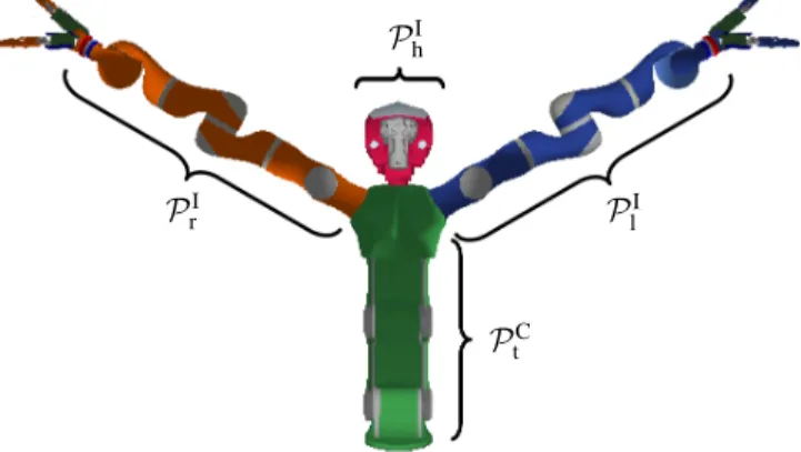
Fig. 2. The decomposition of the humanoid system into elementary parts. The two arms and the head are the “independent” parts and the torso is the “common” one.
robot roadmap composition approaches. In order to avoid combinatorial explosion, elementary roadmaps are computed using PRM-like algorithms that generate compact roadmaps with or without cycles (e.g. PDR [25] or Vis-PRM [15]).
Section IV describes the application of the technique and an empirical performance analysis for planning motions of a three-arm system and of the DLR’s Justin robot in a constrained workspace. The results obtained for these systems show the efficiency of the roadmap composition approach compared to path planing directly for the whole system.
II. MODEL AND PARAMETRIZATION
The first step in our approach is the decomposition of the multi-arm system into elementary parts P1...Pn. Each part
corresponds with a kinematic chain (i.e. a set of joints and bodies). A part Pi is said to be independent, if the change
of its configuration does not affect the pose of other system parts. The independent parts are noted PiI. On the contrary, if
configuration changes of a part act on the pose of other parts, it is said to be a common part, and it is noted PiC. Identifying
independent and common parts can be easily done from an analysis of the kinematic diagram of the multi-arm system.
Figure 2 illustrates the different parts of Justin. Each arm is independent from the other. If the value of an arm joint is modified, the change does not affect the position of any other part in the system. However, a change in one of the torso joints changes the pose of the arms and the head. Considering the definitions above, the head is also an independent part. Thus, this system involves three independent parts: the right and the left arms (PI
r and P I
l respectively), and the head
(PI
h); and a common one: the torso (P C
t ). Given the relatively
low mobility of the head, it can be considered together with the torso in order to simplify the system decomposition.
Note that, for extension to legged (humanoid) robots, the legs would be considered as common parts since moving a leg generally induces the motion of the rest of the robot for maintaining stability.
III. APPROACH
A. Overview
The method proposed in this paper for planning multi-arm robot paths is based on the aforementioned system decomposition into elementary parts. This decomposition permits to split the roadmap construction into two stages. The first stage is to compute a collision-free roadmap Ri for
each sub-system composed by the common parts PC and a single independent part PiI. Such roadmaps construction
considers self-collisions of the sub-system and collisions with the obstacles in the workspace. Any PRM-like method can be used to generate these roadmaps. However, the use of methods generating compact roadmaps such as Vis-PRM [15] or PDR [25] is preferable in order to limit the size of the composite roadmap, which is defined as the Cartesian product of all the sub-system roadmaps, and whose size may become huge if standard PRM methods are used. The PDR algorithm should be in general the most likely choice because it generates useful cycles required for the roadmap composition stage, while keeping the roadmap size sufficiently small.
The constructed roadmaps are then merged into a com-posite one, called Super Graph (SG), extending the idea initially proposed in [24] for the specific case of multiple car-like robots. Figure 3 illustrates the principle of the Super
Graph construction for a system involving two independent
parts (the circle and the square). For each part, a roadmap is constructed. Then, SG is constructed by the composition of the elementary roadmaps. Each node of SG corresponds to a feasible and compatible placement of the two parts, and each edge corresponds to a feasible motion of one or both parts.
Next subsections explain the two-stages of the Super
Graph construction. Subsection III-B explains the
construc-tion of the elementary roadmaps for each independent sub-system. Subsection III-C explains how the elementary roadmaps are merged together into the Super Graph. Finally, path planning queries are solved by searching in SG (Sub-section III-D).
B. Constructing independent PRM
The Path Deformation Roadmaps (PDR) algorithm [25] is a suitable method to compute the elementary roadmap for each sub-system composed by the common parts PC and a
Fig. 3. On the left, elementary roadmaps for a simple system composed by two independent parts (circle and square). The generated Super Graph on the right.
single independent part PiI. The PDR is a recent approach to
sampling-based path planning with PRM methods. The aim is to compute good quality roadmaps that encode the multiple connectedness of the configuration-space inside small but yet representative graphs, that capture well the different varieties of free paths. The approach relies on a notion of path deformability indicating whether or not a given path can be continuously deformed into another existing one. This method extends the Visibility-PRM technique [15], which computes roadmap trees, to construct compact roadmap graphs by adding paths that are not deformable into existing paths in the roadmap (i.e. they belong to different homotopy classes), or if the path deformation is hard. The deformation from one path into another in considered to be hard when a
first-order deformation is not possible. In other words, if it
is not possible to simultaneously go through the two paths while maintaining a visibility constraint between the points of each path.
For constructing a PDR, the roadmap is initialized with a tree structure computed with the Visibility-PRM method [15]. This ensures a good coverage of the free space with a limited number of nodes and edges. Then, iteratively, a free configuration q is randomly sampled and the connectivity of the visible portion of the roadmap is tested (see [25] for details). If the visible sub-roadmap is connected, q is rejected. Otherwise, pairs of connected components of the visible sub-roadmap are linked through q. These new paths are tested to be non-redundant with respect to other added cycles. In such case, they are inserted in the roadmap. The algorithm is stopped when a maximum number of successive failures to create a new useful cycle is reached, meaning that the roadmap is sufficiently rich.
C. Merging independent PRM
The Super Graph construction is made by merging the elementary roadmaps. Merging a node xi from each Ri
creates Super Graph Node X. Two Super Graph Nodes X and Y can be connected via a Super Graph Edge. These two operations are detailed below.
1) Super Graph Nodes: The Super Graph Nodes are
created by the composition of elementary nodes xi in each
roadmap Ri. Figure 4 shows how the merging is done. For
the simplest case of a system composed by n independent parts without any common part (Figure 4 left, “Case A”), each xi is independent from the others. In such case, the
elementary roadmap nodes are directly added up. If there is a common part in the system, two possibilities can be distinguished. In the first case, the configuration of the common parts is the same for all the selected roadmaps nodes (Figure 4 center, “Case B”). In this case, the common parts are kept and the independent parts are merged as in the simplest case. The second possibility is that the common configuration parameters change in the selected roadmaps nodes (Figure 4 right, “Case C”). In this case, the merging consists of creating k Super Graph Nodes (where k is the number of different configurations of PC) and fusing configurations of the independents parts.
Fig. 4. Three cases for merging roadmaps nodes. The boxes marked I represent configurations of independents parts, and boxes marked C are configurations of common parts. Collision detection has to be performed between pairs of parts connected by a dotted arc. Plain arcs indicate pairs of parts that have been checked during the elementary roadmap construction.
Each Super Graph Node is checked for collision in order to ensure the compatibility of the configurations of the different parts. The collision test needs to be performed only partially, since some collisions have already been checked within the elementary roadmap construction. If the system does not involve common parts, or if common parts hold the same configuration in all the elentary nodes (“Cases A and B”), only collision between the independent parts needs to be checked. However, in the general case (“Case C”), each independent part configuration added up to an elementary node has be checked against the other independent parts, the common parts, and the workspace obstacles. Only the collision-free nodes are kept in SG.
2) Super Graph Edges: Once a node X is created and
inserted into SG, its connection to the other Super Graph
Nodes Y is computed. To preserve the efficiency of the
roadmap construction, and due to the high cost of the edge validation stage, a filter is used for selecting the nodes to be checked for connection. This filter uses the information given by the elementary nodes composing the Super Graph Nodes. X and Y can be connected if and only if their composing nodes, xiand yirespectively, are connected in the elementary
roadmaps. For example, let us consider a two arm system. X, constructed from the two elementary nodes x1 and x2, and Y , from y1 and y2, are connectable, if :
• x1= y1 and x2 and y2 are connected in R2 • x1 and y1are connected in R1 and x2= y2
• x1 and y1 are connected in R1 and x2 and y2 are
connected in R2
A possible strategy for saving extra computing time is to construct a roadmap tree instead of a graph. In this case, connection tests (using a local planner) are only performed between Super Graph Nodes belonging to different con-nected component of SG. If we assume that the manipulators are not subject to differential constraints, a straightforward linear interpolation can be used as local planner. Like for the Super Graph Nodes, validating Super Graph Edges only requires to test collisions between pairs of parts and with workspace obstacles that have not been checked when computing the edges of the elementary roadmaps. A Super
free. Otherwise, the elementary nodes xi and yi are tagged
for possible later use (see next subsection).
D. Solving path planning queries
Solving a path planning query consists of adding the start and goal Super Graph Nodes S and G to SG, and searching for a path in this roadmap. If S and G are in the same connected component, the query is directly solved. Otherwise, the Super Graph is enrichment in order to generate other possible paths, or to determine that the query is (probabilistically) not solvable.
Several steps are performed for enriching SG. The first one consists in decomposing the start and goal configurations into configurations of the elementary sub-systems. The con-nection of the resulting nodes siand gito the corresponding
elementary roadmaps Riis tested. If siand giare in different
connected components of Ri, the elementary roadmap is
enriched by further iterating the basic algorithm explained in Section III-B. Note that a failure for solving the path planning query can rise at this stage if a stop condition is reached before connecting siand gi. The newly added nodes
are merged with nodes in the other elementary roadmaps and added to the Super Graph as explained in the Section III-C. However, S and G maybe disconnected even if the all the elementary nodes siand giare connected in their respective
Ri. In this case, several strategies can be used to enrich SG.
The basic one consists of further iterating the elementary roadmap construction and merging stages. Using a smarter strategy, the standard elementary roadmap construction is replaced by a method that samples new elementary nodes xi and tries connections with nodes in the corresponding Ri
that have been tagged during previous Super Graph Edge validation tests. The goal of this strategy is to construct cycles to avoid collisions raised in the roadmap composition stage. Both strategies can be combined and iterated until a solution path is found, or a stop condition is reached (e.g. a roadmap size limit is reached).
IV. RESULTS
This section presents an empirical performance analysis of the proposed method on two multi-arm systems. The first system is composed by three kinematically independent manipulators, and the second one is a model of the robot Justin from DLR, whose decomposition in elementary sub-systems involves common parts. The aim of this analysis is two-fold. First, to compare the performance of the roadmap composition approach with respect to a centralized method that directly constructs a roadmap for the whole robot system. And second, to analyze the influence of the method used to construct the elementary roadmaps on the global performance of the Super Graph planner.
For each system, we defined path planning queries of dif-ferent difficulty. Path planning difficulty increases because of motion constraints imposed by workspace obstacles, as well as by the need of coordinated arm motions. Six algorithms were tested for each path planning problem. Three of them - PDR, Vis-PRM and PRM - compute roadmaps for the
Fig. 5. Two path planning problems for a multi-arms system composed by three Light Weight Robot III arms. “3Arms S.” represents a relatively simple problems, and “3Arms H.” is a more difficult one. The start configurations are on the left, the goal on the right.
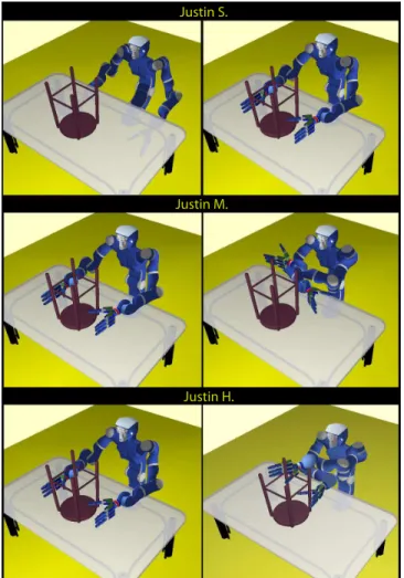
Fig. 6. Start and goal configurations of path planning queries with three difficulty levels for Justin.
TABLE I NUMERICALRESULTS
Problem PDR SG PDR Vis-PRM SG Vis-PRM PRM SG PRM
nnodes T (sec) nnodes T (sec) nnodes T (sec) nnodes T (sec) nnodes T (sec) nnodes T (sec)
3Arms S. 31 13.3 44 2.6 30 3.2 24 0.4 180 2.6 44 0.5
3Arms H. 247 165.8 174.8 11.4 229 130.7 63 2.4 20512 701 2415 17.8
Justin S. 82 23.6 118 2.6 72 18.4 99 1.0 1624 14.9 1719 10.7
Justin M. 161 112.14 258 4.3 158 90.9 223 1.9 8673 202.4 32277 2082 Justin H. – >2h 7269 173.8 – >2h 6494 101.1 – >2h – >2h
whole system. The three others - SG PDR, SG Vis-PRM and SG PRM - apply the presented roadmap composition approach using PDR, Vis-PRM and PRM algorithms to compute the elementary roadmaps. The test consisted of incrementally computing a roadmap until the solution to a given query was found. Obviously, roadmaps able to solve queries of a difficulty level can also solve queries of a lower difficulty one. All the algorithms were implemented into the path planning software Move3D [26]. The experiments reported below have been averaged over 20 runs of the planner. Computing time corresponds to a Dual-Core AMD Opteron processor 2222 at 3.0 GHz.
Figure 5 shows a multi-arm system composed by three Light Weight Robot III arms [27], [28], developed at DLR and currently commercialized by Kuka Robotics. The decom-position of this system yields three kinematically indepen-dent parts, each one corresponding with one of the 7 DOF arms. Two path planning problems are represented in the figure. In problem “3Arms S.”, the three manipulators have to move their end-effector toward three distant points on the surface of a sphere. This motion requires little coordination of the arms. However, in problem “3Arms H.”, the three arms need to coordinate for avoiding collisions while moving inside the U-shaped obstacle.
Figure 6 illustrates three path planning queries for Justin [3] in the same scenario. The robot is composed of two 7 DOF DLR-Lightweight-Robot-III arms [27] mounted on a 3 DOF torso. Justin also holds two four-fingered DLRHand-II hands [29] and a head with a 3 DOF neck. Disregarding the hands and the neck joints, which are considered to be fixed in our experiments, Justin involves 17 DOF. As explained in Section II, this robot can be decomposed into three parts: the arms (with fixed hands) are independent parts, and the torso (with the head) is the common part. In query “Justin S.”, Justin has to move its arms from under the table to over it. This is a simple query that does not require arm coordination. In contrast, arm coordination is a difficult task for solving query “Justin H.”, since Justin has to reach an arduous configurations by totally crossing the arms before grasping the chair. Query “Justin M.” is a medium-difficulty query.
Table I displays the computing time and the number of nodes requires to solve the five path planning queries with the six tested algorithms. Note that results to query “Justin H.” with algorithms PDR, Vis-PRM, PRM and SG PRM are not provided since these planners were unable to compute
solution paths in reasonable computing time (< 2 hours). As also indicated in Figure 7, which represents a lower bound of the gain in computing time, the composition-based planners are faster than the centralized methods in all the cases excepting one. The tendency is only inversed when solving query “Justin M.” using the basic PRM to construct the elementary roadmaps. The reason for this under-performance is that SG PRM spends a lot of time merging elementary PRMs that contain a large number of nodes. This can be seen in Table II, which provides a break-up of the total computing time into the times required for each stage: elementary roadmaps construction and roadmap composition.
Finally note that the performance of SG PDR and SG Vis-PRM is similar. SG Vis-Vis-PRM performs slightly better in terms of computing time. Results in Table II point out that the higher cost for computing the elementary roadmaps with PDR is the main reason for such a slight under-performance of SG PDR. In spite of that, we still suggest the use of PDR for constructing the elementary roadmaps, since the
Fig. 7. Performance gain for the composition (SG) methods against the centralized ones.
TABLE II
TIME REPARTITION FOR THESGCONSTRUCTION(SEC)
Problem SG PDR SG Vis-PRM SG PRM Elem Merge Elem Merge Elem Merge 3Arms S. 2.3 0.25 0.4 0.01 0.08 0.4 3Arms H. 10.3 1.1 2.3 0.02 0.7 17.1
Justin S. 2.2 0.4 0.6 0.4 0.3 10.4 Justin M. 3.4 0.9 1.0 0.9 2.3 2080 Justin H. 94.8 79 44.8 56.3 – –
cycles they contain should be in general very useful for the roadmap composition stage. Besides, solution paths provided by SG PDR are generally shorter.
V. CONCLUSION AND FUTURE WORK We have presented a method for planning multi-arm system motions in constrained workspaces. It is based on the decomposition of the system into kinematically independent parts, which are treated as individual robots in a multi-robot roadmap composition approach. This approach is particularly efficient for manipulation tasks involving several independent manipulators, or for multi-arm systems with a common mobile part having a reasonably small number of DOF. If the system’s common part involves a large number of DOF, the benefit due to the two-stage roadmap construction will be reduced since the roadmap composition stage will be more expensive. Nevertheless, the method is still general and can directly be applied to complex multi-arm systems. The results presented in this paper show the computational benefits of the method.
A possible improvement of the method could be achieved by delaying the Super Graph Edge validation, which is the most expensive operation. The Super Graph could be constructed following the proposed strategy, but running the collision detection test on edges only when needed for solv-ing a particular query, like in the Lazy-PRM algorithm [17].
VI. ACKNOWLEDGEMENTS
The authors thank Christoph Borst and Alin Albu-Schaeffer for providing Justin’s models and related infor-mation. This work has been supported by the European Community under Contract IST 045359 “PHRIENDS” and the European Community’s Seventh Framework Programme FP7/2007-2013 “DEXMART” under grant agreement no. 216239.
REFERENCES
[1] Y. Yamada, S. Nagamatsu, and Y. Sato, “Development of multi-arm robots for automobile assembly,” in IEEE Int. Conf. Robot. & Autom., 1995.
[2] G. Ballantyne and F. Moll, “The da vinci telerobotic surgical system: the virtual operative field and telepresence surgery,” Surgical Clinics
of North America, vol. 83, no. 6, pp. 1293–1304, 2003.
[3] C. Ott, O. Eiberger, W. Friedl, B. Bauml, U. Hillenbrand, C. Borst, A. Albu-Schaffer, B. Brunner, H. Hirschmuller, S. Kielhofer, R. Koni-etschke, M. Suppa, T. Wimbock, F. Zacharias, and G. Hirzinger, “A humanoid two-arm system for dexterous manipulation,” in IEEE-RAS
Int. Conf. on Hum. Robot., 2006.
[4] J.-C. Latombe, Robot Motion Planning. Boston, MA: Kluwer Academic Publishers, 1991.
[5] T. Lozano-P´erez, “Spatial planning: A configuration space approach,”
IEEE Trans. on Comput., vol. 32, pp. 108–120, 1983.
[6] L. E. Kavraki, P. Svestka, J.-C. Latombe, and M. H. Overmars, “Prob-abilistic roadmaps for path planning in high-dimensional configuration spaces,” IEEE Trans. on Rob. & Autom., vol. 12(4), pp. 566–580, 1996. [7] H. Choset, K. M. Lynch, S. Hutchinson, G. Kantor, W. Burgard, L. E. Kavraki, and S. Thrun, Principles of Robot Motion: Theory,
Algorithms, and Implementations. Cambridge: MIT Press, 2005. [8] S. M. LaValle, Planning Algorithms. New York: Cambridge
Univer-sity Press, 2006.
[9] N. M. Amato, O. B. Bayazit, L. K. Dale, C. Jones, and D. Vallejo, “OBPRM: An obstacle-based PRM for 3D workspaces,” in Robotics:
The Algorithmic Perspective (WAFR), P. Agarwal, L. E. Kavraki, and
M. Mason, Eds., 1998.
[10] V. Boor, M. H. Overmars, and A. F. van der Stappen, “The gaussian sampling strategy for probabilistic roadmap planners,” in IEEE Int.
Conf. Robot. & Autom., 1999.
[11] D. Hsu, “The bridge test for sampling narrow passages with proba-bilistic roadmap planners,” in IEEE Int. Conf. Robot. & Autom., 2003. [12] S. Wilmarth, N. M. Amato, and P. Stiller, “MAPRM: A probabilistic roadmap planner with sampling on the medial axis of the free space,” in IEEE Int. Conf. Robot. & Autom., 1999.
[13] D. Hsu, H. Cheng, and J.-C. Latombe, “Multi-level free-space dilation for sampling narrow passages in PRM planning,” in IEEE Int. Conf.
Robot. & Autom., 2006.
[14] M. Saha, J.-C. Latombe, Y.-C. Chang, and F. Prinz, “Finding nar-row passages with probabilistic roadmaps: The small-step retraction method,” Auton. Robots, vol. 19, no. 3, pp. 301–319, 2005. [15] T. Sim´eon, J.-P. Laumond, and C. Nissoux, “Visibility-based
proba-bilistic roadmaps for motion planning,” Advanced Robotics Journal, vol. 14(6), pp. 477–494, 2000.
[16] B. Burns and O. Brock, “Toward optimal configuration space sam-pling,” in Robotics: Science and Systems, 2005.
[17] R. Bohlin and L. E. Kavraki, “Path planning using lazy PRM,” in
IEEE Int. Conf. Robot. & Autom., 2000.
[18] G. S´anchez and J.-C. Latombe, “On delaying collision checking in PRM planning - application to multi-robot coordination,” Int. J. of
Robot. Res., vol. 21(1), pp. 5–26, 2002.
[19] J. Barraquand, B. Langlois, and J.-C. Latombe, “Numerical potential field techniques for robot path planning,” IEEE Tran. on Syst., man
and Cyber., vol. 22, no. 2, pp. 224–241, 1992.
[20] M. Erdmann and T. Lozano-P´erez, “On multiple moving objects,” in
IEEE Int. Conf. Robot. & Autom., 1986.
[21] R. Alami, F. Robert, F. Ingrand, and S. Suzuki, “Multi-robot coopera-tion through incremental plan-merging,” in IEEE Int. Conf. Robot. &
Autom., 1995.
[22] T. Shibata and T. Fukuda, “Coordinative behavior by genetic algorithm and fuzzy in evolutionary multi-agent system,” in IEEE Int. Conf.
Robot. & Autom., 1993.
[23] S. M. LaValle and S. A. Hutchinson, “Optimal motion planning for multiple robots having independent goals,” IEEE Int. Conf. Robot. &
Autom., 1996.
[24] P. Svestka, “Robot motion planning using probabilistic roadmaps,” Ph.D. dissertation, Universiteit Utrecht, 1997.
[25] L. Jaillet and T. Sim´eon, “Path deformation roadmaps: Compact graphs with useful cycles for motion planning,” Int. J. of Robot. Res., vol. 27, no. 11-12, pp. 1175–1188, 2008.
[26] T. Sim´eon, J.-P. Laumond, and F. Lamiraux, “Move3d: a generic platform for path planning,” IEEE Int. Symp. on Ass. and Task Plan., pp. 25–30, 2001.
[27] G. Hirzinger, N. Sporer, A. Albu-Sch¨affer, M. H¨ahnle, R. Krenn, A. Pascucci, and M. Schedl, “Dlr’s torque-controlled light weight robot iii - are we reaching the technological limits now?” in IEEE Int. Conf.
Robot. & Autom., 2002.
[28] A. Albu-Sch¨affer, S. Haddadin, C. Ott, A. Stemmer, T. Wimbock, and G. Hirzinger, “The DLR lightweight robot: design and control concepts for robots in human environments,” Industrial Robot: An International
Journal, vol. 34, no. 5, pp. 376 – 385, 2007.
[29] J. Butterfaß, M. Grebenstein, H. Liu, and G. Hirzinger, “Dlr-hand ii next generation of a dextrous robot hand,” in IEEE Int. Conf. Robot.