HAL Id: tel-02464789
https://tel.archives-ouvertes.fr/tel-02464789
Submitted on 3 Feb 2020HAL is a multi-disciplinary open access L’archive ouverte pluridisciplinaire HAL, est
Study of high damage threshold optical coatings used in
environment with very low hygrometry for fusion class
laser system
Marine Chorel
To cite this version:
Marine Chorel. Study of high damage threshold optical coatings used in environment with very low hygrometry for fusion class laser system. Optics / Photonic. Université de Bordeaux, 2019. English. �NNT : 2019BORD0188�. �tel-02464789�
THÈSE PRÉSENTÉE POUR OBTENIR LE GRADE DE
DOCTEUR DE
L’UNIVERSITÉ DE BORDEAUX
ÉCOLE DOCTORALE DES SCIENCES PHYSIQUES ET DE L’INGÉNIEUR
SPÉCIALITÉ LASER, MATIÈRE ET NANOSCIENCES
Par Marine CHOREL
ÉTUDE DES TRAITEMENTS MULTICOUCHES UTILISÉS DANS
UN ENVIRONNEMENT A TRES FAIBLE HYGROMETRIE SUR
LES INSTALLATIONS LASER DE PUISSANCE
Sous la direction de :
Bruno BOUSQUET, Professeur, Université de Bordeaux
Soutenue le 23 Octobre 2019
Membres du jury :
M. CANIONI, Lionel Professeur, Université de Bordeaux Président
M. MELNINKAITIS, Andrius Associate Professor, Vilniaus Universitetas, Vilnius Rapporteur
M. UTEZA, Olivier Directeur de recherché, LP3, Marseille Rapporteur
M. DEMOS, Stavros Senior Scientist, LLE, Rochester Examinateur
M. GALLAIS-DURING, Laurent Professeur, Institut Fresnel, Marseille Examinateur
M. PINARD, Laurent Directeur du laboratoire des matériaux avancés, Lyon Examinateur
M. LAVASTRE, Éric Ingénieur de recherche, CEA-Cesta, Le Barp Examinateur
Mme RIGATTI, Amy Leader of the optical manufacturing at LLE, Rochester Invitée
Résumé de la thèse (français)
Cette thèse s’inscrit dans le cadre des installations lasers de puissance. Ces installations aux dimensions exceptionnelles permettent d’effectuer diverses expériences dans le domaine de la physique. Augmenter l’énergie et la puissance des lasers reste un enjeu permanent pour atteindre de nouvelles conditions d’interactions laser-matière. Les installations lasers de puissance peuvent être classées dans différentes familles suivant la durée des impulsions laser. Durant cette thèse, nous nous sommes intéressés aux installations du type de Petal (Petawatt Aquitaine Laser) qui opèrent dans le domaine Petawatt avec des durées d’impulsion laser de l’ordre de la picoseconde à la sub-picoseconde (centaines de femtosecondes).
Petal fonctionne sur le principe de l’amplification par dérive de fréquence démontréé par Donna Strickland et Gérard Mourou en 1985 [1]. Cette technique est nécessaire car l’amplification directe d’impulsions courtes (régime picoseconde) est impossible en raison de l’endommagement laser. Elle consiste à étirer dans le domaine temporel une impulsion courte en introduisant un retard de phase sur chaque composante spectrale. L’impulsion étirée dure alors quelques nanosecondes et peut ainsi être amplifiée sans risque d’endommagement laser. Ensuite cette impulsion étirée et amplifiée est finalement compressée en compensant le décalage de phase introduit plus tôt. On obtient ainsi une impulsion courte et très énergétique (Figure 1) qui doit être transportée jusqu’à la cible pour réaliser l’interaction laser-matière souhaitée.
Figure 1. Schéma représentant le principe d’amplification par dérive de fréquence implémenté sur les installations Petawatt
L’amplification par dérive de fréquence a permis de repousser les limites de lasers de puissance et a rendu possible la création de lasers petawatt, tels que Petal. Mais ce qui limite maintenant la montée en puissance de ces installations larser est la résistance à l’endommagement laser des composants optiques utilisés pour le transport du faisceau (Figure 1). En effet, ces compopsants sont exposés à des fluences (densités d’énergie exprimée en J/cm²) extrêmement élevées. La Figure 2 est une photo montrant un miroir de transport de Petal endommagé après un tir à plus d’un petawatt [2]. Ces miroirs sont constitués d’empilements multicouches utilisés sous vide et exposés à des impulsions laser variant entre 0,5 et 10 ps sur une bande spectrale de 3 nm centrée à 1053 nm.
Figure 2. Exemple d’un miroir endommagé sur Petal
L’objectif de cette thèse est d’augmenter le seuil d’endommagement laser des miroirs de transport sous vide de Petal. L’endommagement laser est défini comme toutes modifications irréversibles en surface ou dans le volume d’un composant optique. La résistance à l’endommagement laser peut être caractérisée par une fluence limite appelée la tenue au flux laser du composant (TFL ou LIDT en anglais). En régime picoseconde et sub-picoseconde, ce phénomène est déterministe, ce qui veut dire qu’en dessous de cette fluence il n’y aura pas d’endommagement laser du composant optique. En revanche, au-delà de cette fluence seuil, un dommage pourra être observé à l’endroit du tir laser sous forme d’une décoloration, d’une fracture dans le matériau ou même une délamination des couches.
La façon usuelle de réaliser un miroir est d’alterner des couches minces de deux matériaux d’une épaisseur optique quart d’onde1
(quarter-wave optical thickness QWOT) : un matériau H dit « haut indice » et un matériau L dit « bas indice ». La réflectivité du miroir peut être améliorée en augmentant le contraste d’indice entre les deux matériaux et le nombre de paires de couches.
Pour des empilements multicouches, le seuil de tenue au flux laser est défini comme le minimum du seuil de tenue au flux laser des couches qui le composent :
𝐿𝐼𝐷𝑇𝑚𝑖𝑟𝑟𝑜𝑟 = min(𝐿𝐼𝐷𝑇𝑙𝑎𝑦𝑒𝑟,𝐻, 𝐿𝐼𝐷𝑇𝑙𝑎𝑦𝑒𝑟, 𝐿)
avec LIDTexp,H tenue au flux laser des couches haut indice (bas indice pour L)
Le seuil de tenue au flux laser d’une couche unique (monocouche ou single-layer en anglais) peut être défini de la façon suivante :
𝐿𝐼𝐷𝑇𝑠𝑖𝑛𝑔𝑙𝑒𝑙𝑎𝑦𝑒𝑟=
𝐿𝐼𝐷𝑇𝑖𝑛𝑡
𝐸𝐹𝐼𝑚𝑎𝑥
avec LIDTint la tenue au flux laser intrinsèque du matériau et EFImax le maximum de l’intensité du champ électrique
au sein de la couche.
Ainsi le seuil d’endommagement laser d’un miroir dépend de la distribution de l’intensité du champ électrique 𝐸𝐹𝐼 dans les couches (voir Figure 3) et de la tenue au flux laser intrinsèques (𝐿𝐼𝐷𝑇𝑖𝑛𝑡) des matériaux qui le composent. Nous pouvons observer dans l’exemple de la Figure 3 pour un empilement miroir classique les pics de l’intensité du champ électrique sont situés aux interfaces entre les couches et
Figure 3. Distribution du champ électrique dans un empilement miroir classique
Grâce à cette définition, nous pouvons identifier 3 stratégies d’amélioration du seuil d’endommagement des miroirs de transport de Petal :
- Changer le design : pour déplacer les pics d’intensité du champ électrique dans le matériau le plus résistant
- Changer les matériaux : pour choisir des matériaux avec des meilleurs seuils d’endommagent intrinsèque
- Changer le procédé de dépôt : pour choisir un procédé induisant moins de défauts et de meilleures performances laser.
Dans un premier temps, nous avons considéré théoriquement les deux premiers axes d’étude pour quantifier numériquement les améliorations potentielles. Les résultats font l’objet du chapitre 3 et sont résumés ci-dessous. Une étude bibliographique a permis de lister les matériaux qui pourraient être intéressants de tester lors de cette étude. Ces matériaux sont pour la plupart des oxydes et quelques fluorides. Les paramètres recueillis sont l’indice de réfraction et la tenue au flux intrinsèque (dans par exemple les références : [3,4]). Le choix de matériaux uniquement basé sur ces caractéristiques est difficile, car nous ne savons pas s’il faut privilégier un bon contraste d’indice ou une bonne tenue au flux intrinsèque. Grâce à une étude numérique, il a été possible d’évaluer les performances des matériaux utilisés par paires dans un empilement multicouche et non individuellement. Dans un premier temps, nous avons évalué l’influence des indices de réfraction des deux matériaux sur l’intensité du champ électrique, ce qui nous a permis de conclure que le choix du matériau bas indice a une influence limitée. Par conséquent, il est préférable de choisir le matériau bas indice avec la tenue au flux laser intrinsèque la plus élevée, c’est-à-dire la silice. Dans un second temps, pour hiérarchiser les matériaux « haut indice », nous avons évalué l’influence des deux caractéristiques des matériaux (indice de réfraction et tenue au flux intrinsèque) sur la tenue au flux d’un empilement classique composé de 37 couches d’un matériau H et de silice, voir Figure 4 gauche. Parallèlement, pour améliorer les seuils d’endommagement, nous pouvons ajuster les épaisseurs des 2 couches supérieures de l’empilement de façon à avoir : 𝐿𝐼𝐷𝑇𝑜𝑢𝑡𝑒𝑟 𝑙𝑎𝑦𝑒𝑟,𝐻= 𝐿𝐼𝐷𝑇𝑜𝑢𝑡𝑒𝑟 𝑙𝑎𝑦𝑒𝑟, 𝐿 (nous déplaçons l’𝐸𝐹𝐼𝑚𝑎𝑥 dans le matériau qui a la meilleure 𝐿𝐼𝐷𝑇𝑖𝑛𝑡), voir Figure 4 droite. Ce type de design est appelé dans ce document le balanced design.
Figure 4. 𝐿𝐼𝐷𝑇𝑚𝑖𝑟𝑟𝑜𝑟 pour la polarisation p d’un miroir avec L=SiO2 dans un design classique (droite) et un design avec les deux couches supérieures optimisées (gauche)
Avec ces représentations, nous sommes capables de hiérarchiser les matériaux hauts indices. Nous pouvons voir que Sc2O3 a un fort potentiel. HfO2 reste malgré tout un bon candidat, car il est le matériau le plus couramment déposé et produit des performances similaires à celles de Al2O3 et ZrO2. En comparant les performances d’un balanced design avec celles d’un design classique, nous pouvons voir l’intérêt d’optimiser les empilements.
Pour continuer à explorer ce concept, nous avons développé un algorithme qui optimise un plus grand nombre de couches. Cet algorithme peut être résumé sous la forme schématique suivante, Figure 5.
Figure 5. Schéma de fonctionnement de notre algorithme d’optimisation des designs
Le design d’entrée de l’algorithme est un design classique d’un certain nombre de couches (par exemple 37) avec deux matériaux spécifiques dont l’indice de réfraction et la tenue au flux laser doivent être connues.
exemple, pour de l’e-beam, la gamme d’épaisseurs varie de 20 à 500 nm. A la suite de cette génération aléatoire, les millions de solutions créées sont filtrées avec les critères suivants : une réflectivité supérieure à 99% et une tenue au flux laser supérieure à celle du design intial. A l’issue de cette étape de filtrage, nous avons réduit à quelques milliers le nombre de solutions. Ces solutions peuvent être très bonnes numériquement mais potentiellement non réalisables compte tenue des incertitudes de fabrication. Ainsi pour sélectionner une solution réaliste, une dernière étape de filtrage est appliquée. Cette étape consiste à tester la robustesse des solutions calculées aux incertitudes de fabrication. Ces incertitudes comprennent : les erreurs sur les indices de réfraction, sur les épaisseurs et sur les tenues au flux laser intrinsèque. Elles sont considérées d’abord individuellement puis simultanément dans une erreur cumulative. A la suite de cette sélection sur la robustesse, il ne reste plus qu’un pool de solution avec des performances plus élevées que le design initial. Nous pouvons identifier deux designs intéressants : le « max LIDT design » qui produit les meilleures performances en tenue au flux laser sans erreur cumulative et le « robust design » qui a les performances les plus stables avec ou sans erreur cumulative.
Toutes les simulations du chapitre 3 étant basées sur des valeurs bibliographiques, il est nécessaire de caractériser les indices et les tenues au flux intrinsèque des monocouches afin d’utiliser notre algorithme avec des données d’entrée experimentales.
Notre méthode de caractérisation des monocouches déposées sur échantillons est présentée dans le chapitre 4 ainsi que les nombreux résultats obtenus.
Figure 6. Schéma décrivant notre méthode de caractérisation des matériaux à partir de monocouches
La méthode de caractérisation est résumée dans le schéma ci-dessus. Tout d’abord les indices de réfraction et épaisseurs des monocouches sont déterminés à partir de mesures ellipsométriques et spectrophotométriques. Avec ces données, le maximum d’intensité du champ électrique est calculé pour les conditions des tests d’endommagement laser (angle d’incidence, polarisation, longueur d’onde et environnement). En parallèle de ce calcul, le seuil d’endommagement laser est déterminé sur un banc
d’endommagement. Au cours de cette thèse, deux bancs d’endommangement ont uilisés : un banc CEA foncitonnant à l’air ambiant ou sec et un banc LLE similaire fonctionnant également sous vide. Ensuite, la combinaison de l’𝐸𝐹𝐼𝑚𝑎𝑥 calculé et de la tenue au flux laser mesurée permet de déterminer la tenue au flux laser intrinsèque. Une loi d’échelle temporelle est ensuite appliquée pour recaler tous les résultats des tests à la même durée d’impulsion. Une évaluation précise des incertitudes est importante à chacune de ces étapes de caractérisation. Grâce à une étude paramétrique, il a été possible de définir des configurations de test réduisant les incertitudes sur le calcul de l’intensité du champ électrique. Il est préférable de tester des monocouches d’une épaisseur FWOT (full-wave optical thickness) en incidence normale ou en polarisation p si l’incidence est différente de 0°.
La méthode de caractérisation a été mise en œuvre sur une grande variété de matériaux d’intérêt sélectionnés au cours de l’étude paramétrique. Les valeurs de seuil de tenue au flux laser intrinsèques sont tracées en fonction des valeurs d’indices de réfraction en Figure 7. Contrairement aux résultats couramment observés dans la littérature [3, 5], nous pouvons observer pour un même matériau une forte dispersion des valeurs suivant leur tenue au flux intrinsèque et une faible dispersion suivant l’indice de réfraction.
1.3 1.4 1.5 1.6 1.7 1.8 1.9 2.0 2.1 2.2 2.3 0 1 2 3 4 5 MgF2 SiO2 Al2O3 HfO2 Sc2O3 ZrO2 LaTiO3 Ta2O5 TiO2 Intri ns ic LIDT [J/cm²] Refractive index
Figure 7. Tenues au flux laser intrinsèque des monocouches caractérisées au cours de cette thèse en fonction de leurs indices de réfraction.
Pour mieux comprendre la source de cette dispersion sur les valeurs de tenue au flux laser intrinsèque, l’énergie de bande interdite a été mesurée sur les échantillons grâce à la méthode de Tauc [6]. En Figure 8 sont tracées les valeurs de tenue au flux intrinsèque en fonction des valeurs d’énergie de bande interdite des monocouches de silice et d’hafnium. Sur cette figure, nous pouvons observer que la dispersion suivant la tenue au flux laser ne peut être expliquée par des variations de l’énergie de bande interdite. De plus, ceci implique que les tenues au flux laser intrinsèque ne peuvent être prédites à partir de la connaissance de
5.5 6.0 6.5 7.0 0.5 1.0 1.5 2.0 2.5 3.0 3.5 4.0 4.5 5.0 Mero's law [6] at 700fs Hervy's law [9] at 700fs HfO2 - PIAD 1 HfO2 -PIAD 2 HfO2 - IAD - vendor 1
HfO2 - e-beam 2
HfO2 - IAD 2 - vendor 2 SiO2 - PIAD 1
SiO2 - PIAD 2
SiO2 - IAD - vendor 1 SiO2 - IAD - vendor 2
SiO2 - e-beam 2018
LIDT
in
t [J/cm²
]
Bandgap Energy [eV]
Figure 8. Tenues au flux intrinsèque en fonction des valeurs d’énergie de bande interdite des monocouches de silice et d’hafnium
Pour expliquer la dispersion de ces valeurs nous avons recherché des corrélations avec d’autres grandeurs optiques, notamment avec l’absorption multi-photonique. Pour cela, nous avons mesuré les absorptions des monocouches dans l’ultraviolet. Le détail de cette démarche est présenté en chapitre 5. Le résultat important à retenir est : il existe une bonne corrélation entre l’absorption dans l’ultraviolet et la tenue au flux laser en régime sub-ps dans l’infrarouge (cf. Figure 9).
0.5 1.0 1.5 2.0 2.5 3.0 0.0 2.0x10⁻⁸ 4.0x10⁻⁸ 6.0x10⁻⁸ 8.0x10⁻⁸ 1.0x10⁻⁷ 1.2x10⁻⁷ HfO2 - PIAD 1 HfO2 - PIAD 2 SiO2 - PIAD 1 SiO2 - PIAD 2 HfO2 - IAD - vendor 1
HfO2 - e-beam 2018 HfO2 - IAD 2015 - vendor 2
HfO2 - IAD 2017 - vendor 2 (on Bk7 substrate)
HfO2 - IAD 2017 - vendor 2
Linear fit of Hafnia data
Normalized
PHI signal at 3
55nm
[V/nm]
LIDTint[J/cm²]
Figure 9. Valeur du signal correspondant à l’absorption des échantillons à 355 nm en fonction des seuils de tenue au flux laser intrinsèque à 1053 nm
Grâce à l’algorithme présenté dans le chapitre 3 et les valeurs expérimentales obtenus dans le chapitre 4, il a été possible de calculer des designs à hautes tenues au flux laser et robustes aux erreurs de fabrications. Les premières caractérisations étant effectuées à l’air ambiant pour des raisons de disponibilité, nous avons validé notre méthode d’optimisation en air ambiant avec une amélioration de l’ordre de 44% de la tenue au flux laser. Ensuite, comme les miroirs de transport de Petal sont utilisés dans le vide, la même démarche a été appliquée pour calculer des designs optimisés sous vide (Cf. Tableau 1).
Tableau 1. Performances des trois designs utilisés sous vide
Classical design Vacuum - Robust design Vacuum - Max LIDT design Vacuum -
Reflectivity at 1053 nm p-pol, 45° AOI 99.8% 99.4% 99.5% Predicted LIDT p-pol [J/cm²] 1.41 2.07 2.53 Measured LIDT p-pol [J/cm²] 1.41±0.08 2.22±0.11 2.44±0.14 Improvement on the LIDT compared to classical design -- +57% +73%
Les résultats exposés dans le Tableau 1 montrent que le Max LIDT design produit par notre algorithme d’optimisation fourni une amélioration de la tenue au flux laser de 73% par rapport à un design classique de miroir.
L’objectif de cette thèse a été atteint sur des échantillons. Il reste maintanant à la transposer sur des composants de taille réelle (610 mm x 430 mm x 80 mm ). En outre, cette démarche peut être appliquée à d’autres problématiquse d’empilements multicouches tels que polariseurs, réseaux et miroirs à large bande.
Références du résumé
[1] D. Strickland and G. Mourou. Compression of amplified chirped optical pulses. Opt. Comm., 55(6):447–449, 1985.
[2] N. Blanchot, G. Béhar, J.C. Chapuis, C. Chappuis, S. Chavardoine, J.F. Charrier, H. Coic, C. Damiens-Dupont, J. Duthu, P. Garcia, J. P. Goossens, F. Granet, C. Grosset-Grange, P. Guerin, B. Herbard, L. Hilsz, L. Lamaignère, T. Lacombe, E. Lavastre, T. Longhi, J. Luce, F. Macias, M. Mangeant, E. Mazataud, B. Minou, T. Morgaint, S. Noailles, J. Néauport, P. Patelli, E. Perrot-Minnot, C. Present, B. Remy, C. Rouyer, N. Santacreu, M. Sozet, D. Valla, and F. Laniesse. 1.15 PW - 850 J compressed beam demonstration using the PETAL facility. Opt. Express, 25(15):16957–16969, 2017.
[3] L. Gallais and M. Commandré. Laser-induced damage thresholds of bulk and coating optical materials at 1030 nm, 500 fs. Appl. Opt., 53(4):A186–A1966, 2014.
[4] M. Mende, S. Schrameyer, and H. Ehlers. Laser damage resistance of ion-beam sputtered Sc2O3/SiO2 mixture optical coatings. Appl. Opt., 52(7):1368–1376, 2013.
[5] B. Mangote, L. Gallais, M. Commandré, M. Mende, L. Jensen, H. Ehlers, M. Jupé, D. Ristau, A. Melninkaitis, J. Mirauskas, V. Sirutkaitis, S. Kicas, T. Tolenis, and R. Drazdys. Femtosecond laser damage resistance of oxide and mixture oxide optical coatings. Opt. Lett., 37(9):1478–1480, 2012.
[6] J. Tauc, R. Grigorovici, and A. Vancu. Optical properties and electronic structure of amorphous germanium. phys. stat. sol., 15(627), 1966
Acknowledgement
The thesis you are about to read…Yes, because I am hoping that you, dear readers, are about to read the whole thesis and not just this acknowledgement section. I am trusting you, you can do it ! ;-) So let’s start again!
The thesis you are about to read presents the work and production of three years of hard work where I was able to express myself, discover and reveal my love for research (especially in the thin films context) and communication. I really enjoyed this experience and all the experiments, simulations, discussions, meetings it required. In the following pages I would like to acknowledge all the people you made this possible.
I would like to begin by thanking the members of my defense committee for accepting to judge my work and be part of the finalization of this thesis. I would like to thank especially Olivier Uteza and Andrius Melninkaitis for reviewing this thesis. All your remarks allowed considering new questions and improving this present paper. I will also acknowledge Lionel Canioni, Stavros Demos, Laurent Gallais-During, Laurent Pinard and Amy Rigatti for reading this thesis and for their comments and questions during the defense.
Then I would like to thank all the people who mentored and guided me during this work. The first two people I am thinking of are Eric and Thomas, my super CEA mentors. You were both very complementary in your daily coaching, thank you for all the things you taught me, all the time we spent working, talking and discussing the way to make/take. Thank you for everything. Thank you Thomas for selecting me for this polarizer’s internship that started all.
I would like then to thank my incredible PhD supervisor Bruno. Thank you for your involvement, your outside look that allows to synthesize everything, to fix the goals and to guide this work in the right direction. I would like also to deeply thank you and Eric for all the essential help and corrections during the difficult time of writing this thesis.
Then I wish to acknowledge Jérôme N. & Stavros for creating this collaboration between CEA and LLE on the topic of short pulses laser-induced damage. These exchanges to Rochester undoubtingly broaden my point of view on work, on the world and life. It was a real life experience and I am deeply grateful for this opportunity. You both guided me through this work and helped me synthesized, write and also rewrite articles and this thesis as well. All of this taught me a lot.
I would also like to thank Nicolas Bonod for his involvement in my work. The time I spent at Institut Fresnel led to the development of the optimization algorithm as it is. You also helped me a lot on the writing
my application and their help in improving it. I wish to thank Stéphane S. too for letting me participate at the “Festival du film pas trop scientifique”. This film contest was the first contest I participated during this PhD and it revealed my love to popularize my Ph.D research. Even though my participation to those contests wasn’t successful I learned a lot and I was very pleased to represent CEA.
Then I wish to thank Bernard, François and both Jérômes (N. and D.) for their overviews on my work as head of the department, service and laboratory. More importantly I would like to thank you all for hiring me after this PhD studies. I am truly appreciative for being able to continue this research as part of my new position and to still be a part of the collaboration between CEA and LLE.
I would like to also thank the CEA communication service (UCAP) for asking me to participate to the interview from “Sciences et Vie Junior” for the article on the LMJ and Petal. I never thought I could be cited and thanked in this magazine that allows young people to discover sciences.
Finally I would like to thank all the people I worked with during these three years: all the people from both LTO and LMO and all the people I met at LLE. You all welcomed me with such kindness and well-meaning that Bordeaux and then Rochester felt almost like home. I am writing almost because everyone should know that Brittany (the place, Bretagne in French) remains the best place on earth.
To the people in LTO, I am thanking each and every one of you: apprentices, interns, post-docs and permanent members of the team for being so nice colleagues. I would like to address special thanks to Daniel for all the board games you made us discover. I only knew Monopoly before coming to LTO.
Among the entire person I met at LLE I am addressing my special thanks to Semyon who taught me a lot and made a considerable number of measurements for me. Your passion to optics and sciences is a real source of inspiration and I really enjoyed talking with you during my stay at LLE. I am also appreciative of all the damage tests performed by Alexeï and all the discussion we had on laser-induced damage, music and anything else. I am also very grateful to Amy and Jim for everything they taugh me on coatings and all the discussion we had. Finally, I wish to acknowledge the undeniable involvement of Brittany (the person this time and not the place in France) in this work with all the measurements, observation and everything you have done and also for making me feel comfortable in Rochester. You accomplish an incredible work and you are a great person. I would like to thank Katelynn and Debbie too for their warm welcome at LLE and this week-end in London where we met a backstreet boy. And thank you Katelynn for taking time to correct some spelling and grammar mistakes I made in this thesis. I am looking forward seeing all of you again in Rochester soon.
Among the people from LMO, I directing my special thanks to Nadja for all the damage testing you performed with me, for teaching me how to use DERIC and everything else; to Isabelle for all the measurements you performed for me during this PhD and internship and for teaching me how to use the two spectrophotometers; to Laurent for exchanging about laser-induced damage and advising me on conferences, articles and thesis writing and finally to Stéphane for teaching me a lot about interferometry, power and for your advises.
Finally, I would like to thank all the friends I made when I arrived in Bordeaux: Clémence, Florian, Mathilde, Martin, Mélanie, Nicolas (Bonjour !), Noémie, Pierre-Marie and Roxane. Thank to you all I discovered Bordeaux and spend some incredible times and evenings here. Even though you are not all in Bordeaux anymore, I know we will continue to see each other anywhere in the world. As we experienced
with Nicolas when we travelled on these week-ends to discover the east of the America (Washington, Minneaspolis, Rochester, Niagara Falls, Toronto) and the one in New York with Clémence too. It was super and I still remember our songs with a smile. I am sorry because I didn’t keep my cape forever and ever like you said you will.
I wish to add some special thanks here to Florian. We both began our thesis almost together and we are finishing them with just 5 days apart. I really enjoyed spending this three years working alongside you, all these shared trainings, all these discussions and laughs exchanged, all of our presentation that followed one another. I would like to thank you, Noémie and my sister, Colette, for this incredible road trip in the west of the USA. We saw the grand Canyon, Las Vegas, the death valley, the Yosemite forest, San Francisco, the quite traumatic Alcatraz, the west coast, Santa Barbara and finally Hollywood. It was great, crazy, tiring (all these miles driving) and unbelievable. I never thought I will be a witness at a wedding in Las Vegas, especially not the wedding of such great friends as you both are. Thank you! Et Bisous !
To finish this section and the writing of this thesis, I wish to acknowledge those you have always been there and always will: ma famille.
Table of content
Résumé de la thèse (français) ... i
Acknowledgement ... x
Table of content ... xiii
Glossaire ... xvi
Introduction (français) ... 1
Introduction ... 3
Chapter 1 High power facilities: objectives and challenges ... 5
1.1 High power Laser facilities: Presentation of Petal & LMJ ... 6
1.1.1 High power laser facilities or fusion class laser: purposes and architecture ... 7
1.1.2 Architecture of Fusion Class Laser: LMJ & Petal example ... 11
1.2 Laser damage challenges in high power laser facilities ... 21
1.2.1 Fundamental of laser-induced damage ... 21
1.2.2 Nanosecond facilities ... 23
1.2.3 Pico and sub-picosecond facilities ... 24
Summary of Chapter 1... 28
Chapter 2 Multilayer Dielectric coatings ... 29
2.1 Principle of MLD coatings ... 30
2.1.1 Dielectrics ... 30
2.1.2 Single layer example ... 34
2.1.3 Multilayer ... 36
2.2 Laser damage and MLD ... 41
2.2.1 Short pulse LIDT on MLD ... 41
2.2.2 Survey of the models ... 42
2.3 Fabrication of multilayer dielectric component ... 46
2.3.1 Survey of thin film manufacturing ... 46
2.3.2 Deposition Methods ... 47
2.3.3 Manufacturing Petal transport mirror ... 51
Summary of Chapter 2... 54
Chapter 3 Design and optimization of dielectric multilayers with high LIDT in the sub-ps regime ... 55
3.1.1 Background on materials ... 56
3.1.2 Numerical parametric study ... 61
3.2 New Design: Optimization of multilayer stacks ... 68
3.2.1 Background on design ... 68
3.2.2 Background on design optimization algorithms ... 71
3.2.3 Presentation of the optimization algorithm ... 72
3.2.4 Example of application of our robust optimization algorithm ... 73
Conclusion of Chapter 3 ... 78
Chapter 4 Characterization of monolayers ... 79
4.1 Intrinsic LIDT characterization ... 80
4.1.1 Measurement of the refractive index and thickness ... 81
4.1.2 Calculation of the Electric field intensity ... 83
4.1.3 LIDT measurement with 1-on-1 procedure ... 88
4.1.4 Calculation of the intrinsic LIDT ... 91
4.2 Results: description of the set of samples tested in ambient air ... 91
4.3 Influence of the environment on monolayers properties ... 94
4.3.1 Ambient Air Vs Dry Air ... 94
4.3.2 Vacuum Vs ambient Air ... 95
Conclusion of Chapter 4 ... 100
Chapter 5 Toward nondestructive characterization of the intrinsic LIDT ... 101
5.1 Intrinsic LIDT and refractive index comparison ... 102
5.2 Limits of Mero’s Law ... 104
5.2.1 The Tauc Method... 104
5.2.2 Results ... 105
5.3 Correlation to other optical signature ... 106
5.3.1 Correlation to spectrophotometry measurement... 107
5.3.2 Correlation to photothermal absorption measurements ... 112
Conclusion of Chapter 5 ... 116
Chapter 6 Design optimization ... 117
6.1 Experimental validation of our algorithm: Optimization for air use ... 118
6.2.2 Study of the potential Influence of the mechanical stress on LIDT ... 126
6.2.3 Intrinsic LIDT determination in vacuum from multilayers ... 131
6.3 Optimization of the Final design ... 131
6.3.1 Expected numerical LIDT results ... 131
6.3.2 Results ... 133
Conclusion of Chapter 6 ... 137
Conclusion ... 138
Perspectives on multilayer dielectrics components used in high power laser facility ... 140
1. Mirrors ... 141
1.1. Petal Transport Mirrors ... 141
1.2. Broadband chirped mirrors (15 fs) ... 142
2. Other optical functions ... 142
2.1. Polarizers ... 142
2.1.1. LMJ polarizers specification and designs ... 142
2.1.2. Aging effect: irreversible phenomenon... 143
2.1.3. Effect of the relative humidity: reversible phenomenon ... 144
2.2. Petal gratings ... 145
Summary of the perspectives ... 146
Conclusion (français) ... 147
Glossaire
AR : anti-reflective/ anti-reflection
CEA : Commissariat à l’Énergie Atomique et aux Énergies Alternatives in french to be translated as the French Alternative Energies and Atomic Energy Commission
CPA : Chirped Pulse Amplifaction CTBT : comprehensive test ban treaty
EFImax : maximum of the electric field intensity inside a layer or a multilayer coating ELI : Extreme Light Infrastructure
FI : fast ignition FS : fused silica
FWOT: full-wave optical thickness layer HR : highly-reflective/ high-reflection HWOT : half-wave optical thickness layer ICF : inertial confinement fusion
LASER : light amplification by stimulated emission of radiation LEHs : laser entrance holes in Fig. 5:
LID : laser-induced damage
LIDT : laser-induced damage threshold LIDTint : intrinsic LIDT
LLE : Laboratory for Laser Engergetics
LLNL: Lawrence Livermore National Laboratory
LMJ : Laser MégaJoule MLD : multilayer dielectric MPA : pre-amplifier module MPI : multi-photon ionization NIF : National Ignition Facility
NIF-ARC : National Ignition Facility – Advances Radiographic Capability PEPC : plasma electrod pockels cell
Introduction (français)
En 2018, le prix Nobel de physique a été décerné aux professeurs Donna Strickland et Gérard Mourou pour le développement de l’amplification par dérive de fréquence (chirped pulse amplification, CPA). Cette technique a rendu possible la création de Laser Petawatt. Cette récompense a été une grande reconnaissance pour la communauté de la photonique et des lasers.
En effet, depuis la création du premier laser en 1960, les scientifiques ont toujours cherché à atteindre des puissances et des énergies laser plus élevées [1]. Durant les trois dernières décennies, se sont ainsi développées autour du globe de gigantesques installations laser : les installations laser de puissance. Parmi ces installations on peut notamment citer le Laser MégaJoule et Petal implantées près de Bordeaux en France.
Fig. 1. Répartition géographique des installations laser de puissance dans le monde (haut) et augmentation de la puissance de ces lasers au fil des années (bas). Cette figure est extraite de [1]
L’un des principaux défis de ces installations est de comprendre et d’appréhender l’endommagement laser des centaines de composants contenus dans ces systèmes laser. Plus particulièrement, sur l’installation Petal, le seuil de tenue au flux laser des miroirs de transport est actuellement le facteur limitant de la montée en puissance de l’installation. Ces miroirs de transport sont constitués à partir d’un empilement de couches minces de plusieurs matériaux diélectriques déposés sur des substrats en silice ou verre. La principale motivation de cette thèse est d’augmenter le
seuil de tenue au flux laser (laser-induced damage threshold, LIDT) de ces composants multicouches (MLD) utilisés en régime sub-picoseconde. Les stratégies d’amélioration de cette tenue au flux laser consistent en la recherche de meilleurs designs, matériaux et/ou techniques de fabrication.
Ce travail de thèse s’appuie sur une approche numérique originale ainsi que sur une solide validation expérimentale. Tout d’abord, nous avons développé notre propre algorithme d’optimisation des empilements multicouches permettant de concevoir des empilements performants et robustes aux erreurs de fabrication. Ensuite, des matériaux soigneusement sélectionnés ont été caractérisés puis testés vis-à-vis de leur tenue au flux laser. La présentation des méthodes employées et résultats obtenus est organisée comme suit.
Le contexte général dans lequel s’inscrit ce travail est présenté dans le premier chapitre à travers une vue d’ensemble sur les installations laser de puissance dans le monde. Ensuite les installations Laser MégaJoule (LMJ) et Petal sont présentées plus en détails. Pour finir ce chapitre introductif, les principaux mécanismes à l’origine de l’endommagement laser sont présentées puisque comprendre et surpasser l’endommagement laser reste un des défis principaux de ces installations.
Le chapitre suivant présente les connaissances nécessaires à l’étude des empilements multicouches de matériaux diélectriques en décrivant comment l’intensité du champ électrique est calculée à l’intérieur de la structure multicouches, et comment sont conçus et fabriqués les empilements multicouches. Au travers de cette présentation, les trois axes d’amélioration de la tenue au flux laser cités ci-dessus seront dégagés. Le premier consiste à considérer de nouveaux matériaux, le second porte sur l’amélioration des empilements via de nouveaux designs optimisant la distribution du champ électrique. Le dernier axe d’amélioration porte sur la recherche de nouvelles techniques de dépôts.
Ensuite dans le troisième chapitre, les deux premières stratégies d’optimisation seront examinées numériquement et les améliorations seront quantifiées. Cette étude théorique basée sur un calcul numérique a mené au développement d’un algorithme d’optimisation robuste qui sera présenté au cours de ce chapitre.
L’application de cet algorithme requiert la caractérisation préalable de matériaux. Les matériaux à fort potentiel repérés au cours de l’étude théorique ont donc été caractérisés et les résultats de ces divers matériaux associés à différentes méthodes de dépôt, présentés dans le chapitre 4, seront analysés pour remettre en cause certaines corrélations entre paramètres physiques publiées bien avant ce travail.
Dans le chapitre 6, l’algorithme d’optimisation est appliqué en utilisant les résultats expérimentaux présentés dans le chapitre 4. En concevant un empilement multicouche il est important de maintenir la réponse spectrale souhaitée suivant l’environnement et au cours du temps. L’influence de l’humidité relative et du vide sur les performances en tenue au flux laser des traitements a ainsi été étudiée.
Introduction
In 2018, the Nobel Prize in physics was awarded to Professor Donna Strickland and Gerard Mourou for the development of the technique of chirped pulse amplification (CPA), which made possible the creation of ‘Petawatt Class Lasers’. This award was a great achievement for the laser research community.
Indeed, since the invention of laser in the 1960, scientists have been working at always reaching higher energies and higher power [1]. The past decades have seen the development of several gigantic laser facilities around the world: the high power facilities. Among those, one can cite the LMJ and Petal facilities installed near Bordeaux in France.
Fig. 2. Geographic distribution of high-peak-power lasers (top) and increase of power of those lasers regarding the years (bottom). This figure is taken from [1]
One of the main challenges of those facilities is to understand and overcome laser-induced damage on the thousands of optical components in the laser system. Especially, on the Petal laser facility, the laser-induced damage threshold of the transport mirror is currently limiting the overall power of the laser. Those transport mirrors are made of coatings manufactured by stacking a multitude of thin films of various dielectric materials on a fused silica or glass substrate. The main motivation of this PhD study is to develop methods to increase the laser-induced damage threshold (LIDT) of such multilayer
dielectrics (MLD) mirrors used in sub-picosecond regime. The paths considered to achieve this goal are:
- Improving/changing the materials, - Improving/changing the designs
- or optimizing/changing the manufacturing process.
This PhD work combines a specific and innovative numerical approach with extensive experimental validation. Firstly, we developed our optimization algorithm is robust to manufacturing errors. Secondly, an arrayof materials was considered and characterized with a spectrophotometer and an ellipsometer, and were finally laser damage tested throughout of this work.
The presentation of methods and results is organized as follows.
In a first chapter, the general context in which this work takes place is presented by first giving an overview of the high power lasers in the world. Then the LMJ/Petal facilities are presented in more details. To finish, we present the main mechanism at the origin of laser-induced damage, since one of the main challenges of these facilities is to understand and manage the laser-induced damage to optical material.
The following chapter presents the background necessary to study MLD components, explaining how to calculate the electric field intensity in a MLD structure, and how to design and manufacture MLDs. Throughout this presentation, the three axes of improvement of the mirrors LIDT, cited above, will be disclosed. The first one considers new materials exhibiting higher intrinsic LIDT than the reference materials. The second one improves the design by re-engineering the near electric field distribution. The last one investigates other deposition methods than the one currently used.
In Chapter 3, we examine the two first paths of increasing the LIDT theoretically and calculate the improvement those change can bring. This theoretical study led to the development of a robust optimization algorithm, presented within this chapter.
To apply this algorithm, the materials with high potential highlighted in Chapter 3 have been characterized. Those materials associated with various deposition process and their characterizations are presented in Chapter 4. They lead to reconsider the model establishing a link between the bandgap energy and the intrinsic LIDT on MLD, in Chapter5.
In Chapter 6, the robust algorithm is applied using the values determined in the Chapter 4. When designing optical multilayer dielectric component, it is important to obtain and maintain the desired spectral response. The influence of the environment has been assessed throughout this work.
Finally, in the last part of this thesis we will discuss the future prospects of research brought by this present work and the future improvement that could be performed on the algorithm so it can be
Chapter 1
High power facilities: objectives
and challenges
1.1 High power Laser facilities: Presentation of Petal & LMJ ... 6
1.1.1 High power laser facilities or fusion class laser: purposes and architecture ... 7 1.1.1.1 Overview of high power laser facilities ... 7 1.1.1.2 Military applications ... 8 1.1.1.3 The Civilian Applications ... 9 1.1.2 Architecture of Fusion Class Laser: LMJ & Petal example ... 11 1.1.2.1 Establishment of LMJ and Petal ... 11 1.1.2.2 Architecture of LMJ Beam Line [29] ... 14 1.1.2.3 Architecture of PETAL ... 17
1.2 Laser damage challenges in high power laser facilities ... 21
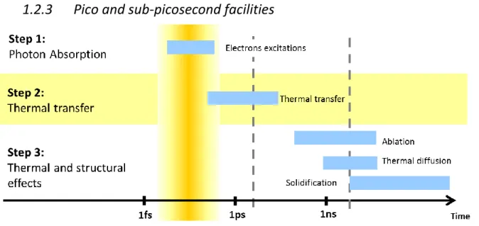
1.2.1 Fundamental of laser-induced damage ... 21 1.2.2 Nanosecond facilities ... 23 1.2.3 Pico and sub-picosecond facilities ... 24 1.2.3.1 Mechanisms during laser damage in short pulses regime ... 25 1.2.3.2 Laser damage on Petal ... 26
This chapter provides an overview of high power laser facilities that are operating or under development around the world and some of their main goals. This PhD thesis is specifically carried out in the framework of the LMJ/PETAL facilities. Therefore, a second part of this chapter presents the architecture of both LMJ and PETAL lasers in more details. The objective of high power laser facilities is to push forward the limits of laser power and energy. However, this challenge requires overcoming laser-induced damage. This issue limits laser power and plays a key role in all high power laser facilities. The physical mechanisms at the origin of laser-induced damage will be discussed in this chapter.
1.1 High power Laser facilities: Presentation of Petal & LMJ
Since its creation in the sixties [2] and with the development of the semi-conductor industry, lasers tend to become always smaller with the rise of semi-conductor laser diodes. This miniaturization has brought lasers into daily life and industry. They are widely used in telecommunications, telemetry, surgery, fabrication by laser processing, LIDAR, laser pointers, LIBS among many other applications. Still, the past few decades have seen the development of extraordinary large lasers, the size of high power laser facilities becoming comparable with the size of buildings. This development was motivated by the need to reach higher energies and higher powers (see Fig. 3). High power lasers open new fields of investigation for physicists and bring light matter interactions to high field and relativistic optics. One of the main outcomes of high power lasers is to foster thermonuclear fusion.
1.1.1
High power laser facilities or fusion class laser: purposes and
architecture
High power lasers aim at yielding extraordinarily high temperatures and pressures onto a very small volume. The laser facilities will foster unprecedented electric fields in a short time and a confined space and this will open novel routes in high field physics. Although laser facilities share the same objective to achieve strong light-matter interactions, they feature different characteristics and target different applications. Among the wide variety of goals, the generation of X-rays and gamma rays, neutrons and electrons are highly needed. Some of the applications of those facilities will be more detailed in this section.
1.1.1.1
Overview of high power laser facilities
High power laser facilities are developed in different regions of the world [1, 4], see Fig. 1. Two different laser facility families can be distinguished: the nanosecond facilities (10-9 s) and the pico/sub-picosecond facilities (10-12 s and <10-12 s). Nanosecond facilities were the first to be developed. The National Ignition Facility (NIF) is the largest mega-joule facility. Its construction started in 1997 at Lawrence Livermore National Laboratory (LLNL, USA). NIF was inaugurated in 2009 and designed to reach 1.8 MJ and 500 TW at 351 nm with 192 laser beams [5]. Another American nanosecond laser facility called OMEGA was developed at the Laboratory for Laser Energetics (LLE) at the University of Rochester (NY, USA). Construction and commissioning of OMEGA were in 1995 [6]. It hosts 60 laser beams that can focus up to 40kJ in the UV (351 nm). In France, the Megajoule Laser (LMJ) started to operate in 2014 while still being under construction. When the LMJ construction reaches completion in 2022, LMJ will host 176 laser beams and will deliver 1.4 MJ at 351 nm [7]. One can also cite the SG-IV project (SG stands for Shenguang which means Divine Light) in China, that follows the success and specification validation of the SG-III which counts 48 laser beams designed to deliver up to 200 kJ [8]. Considering the size and complexity of those facilities, an important effort was made first to design the architecture of the facility and to select the specifications of the optical components and tooling from “smaller” projects. Then those facilities were constructed and inaugurated several years later.
The pico/sub-picosecond facility family was developed later using the chirped pulse amplification (CPA) method proposed in 1985 by Donna Strickland and Gerard Mourou [9]. CPA will be presented in more detail in the following paragraph when describing the architecture of Petal. Pico/sub-picosecond lasers present a large variety of pulse-time duration, and therefore a wide variety of energies and powers, see in Fig. 4.
In the kJ-ps range, for petawatt to multi-petawatt facilities, one can cite Omega EP (Extended Performance) at LLE [10, 11] and NIF-ARC (Advances Radiographic Capability) at LLNL in the USA [5], Gekko and LFEX in Japan [12], Orion and Vulcan in the United Kingdom [4] and finally Petal in France [7, 13, 14]. In May 2015, the Petawatt Aquitaine Laser, named Petal, demonstrated to be one of the most powerful single beam in operation with a 1.15 PW shot at 850 J and 1053 nm [14]. As presented in Fig. 4, Petal aims at further increasing its power and energy from 1.15 PW and 1 kJ to
5 PW and 4 kJ. This significant increase will strongly challenge the resistance of optical components to laser damage. This issue of laser damage resistance in the context of the Petal project motivated this PhD thesis.
Fig. 4. Petawatt class lasers in the world: energy per beam with respect to the power per beam. Figure taken from [15]
Also installed in France, but with much shorter pulses of 15 fs, the Apollon laser [16] was inaugurated in 2015. The Apollon laser was designed to be the most powerful laser to deliver initially 5 PW pulses and then increasing this power up to 10 PW. These performances are now surpassed by the Thales laser of ELI-NP facility, which stands for Extreme Light Infrastructure - Nuclear Physics. Indeed, in March 2019, Thales reported a 10 PW laser shot [17]. ELI-NP is part of the European project ELI [3, 18]. This project consists of three laser facilities located in 3 different countries: ELI-ALPS (Attosecond Light Pulse Source) in Hungary aims at delivering ultrashort pulses from the femtosecond (10-15 s) to the attosecond (10-18 s) domains [19], ELI-Beamlines in Czech Republic will be a high-energy beam facility delivering short pulses, and finally ELI-NP (Nuclear Physics) in Romania will couple two 10 PW laser beams with a brilliant gamma source. The ELI facilities aim to be fully operational in 2020.
Many of these facilities aim to produce thermonuclear ignition for military and/or civilian applications. The Laser MégaJoule (LMJ) in France and National Ignition Facility (NIF) in the USA share that objective for both military and civilian applications.
prevent any such nuclear explosion at any place under its jurisdiction or control [20]. To deter nuclear threats, it is necessary to assess the reliability of the stockpile of the nuclear weapons without testing them.
For that purpose, France launched an ambitious program called “Simulation” that aims to numerically model nuclear weapons. This requires additional knowledge in high energy physics and to get additional experimental data. This program combines the use of an original set of computation and experimental facilities. The computational facility located at Bruyère-Le-Châtel (32km southwest of Paris) hosts the Tera-1000-2 center. Tera-1000-2 is the most powerful computer in France and the sixteenth in the world according to the TOP500 of November 2018 [21]. The experimental facilities are the X radiography generator, Airix installed in the Epure facility, located in Salives (45km north of Dijon) [22] and the laser facility, LMJ, located in Le Barp (20km south of Bordeaux). Both facilities assess specific portion of the functioning of the nuclear weapons. LMJ allows the study of the behavior of matter in extreme conditions similar to the thermonuclear fusion happening during the final stage of the explosion of nuclear bomb.
1.1.1.3
The Civilian Applications
Civilian applications for thermonuclear ignition are the production of electricity and a better understanding of high energy physics.
By inflicting high temperature and high pressure onto a small target filled with lightweight atoms like deuterium (D) and tritium (T), they will fuse into heavier atoms such as helium and release neutrons, as shown in Eq. (1.1):
𝐻 1 2 + 𝐻 1 3 → 𝐻𝑒 2 4 + 𝑛 0 1 (1.1)
Thermonuclear fusion is associated with a creation of a neutron and a strong release of energy. This energy will lead to a huge rise of the temperature that can be used to produce electricity.
Two methods use lasers to achieve thermonuclear fusion: inertial confinement fusion (ICF) and fast ignition (FI).
Inertial Confinement Fusion [23] consists of heating and compressing a very small fuel target (smaller than a centimeter: Fig. 5) enclosing a capsule containing a mixture of deuterium and tritium (D-T) with multiple very high energy laser beams. Fig. 5 shows a schematic of a classical ICF target where the D-T capsule is inside a cylindrical gold hohlraum. The capsule is supported by a thin membrane (15-100 nm) called the tent.
Fig. 5. Schematic of a classical ICF target. The cylindrical hohlraum encloses the ICF capsule supported by a thin (15-100 nm) membrane (the tent). Laser beams enter the hohlraum through the laser entrance holes (LEHs). Figure taken from [23]
The different laser beams are uniformly spread around the target and focused on it. They enter the target through two opposite holes (called laser entrance holes in Fig. 5: LEHs). The inner surface of the target is heated by the laser-matter interaction (Fig. 6(b1)). The strong local electric field of the laser beam accelerates the electrons of the gold capsule which produces rays (Fig. 6(b2)). The X-rays generated by the laser beams focused on the gold capsule will compress and heat the core of the target (Fig. 6(b3)) until the target implodes (Fig. 6(b4)). This implosion will create temperature of billions of degrees allowing the fusion of the D-T mixture. This ICF concept is being explored with nanosecond megajoule facilities.
Fig. 6. (a) picture of a gold target-(b1-b4): Illustrations of the gold target and principles of Inertial Confinement Fusion. Figures taken from [24] based on [5] resources
Fast ignition is a variant of ICF principles. The difference between the two techniques is that with the fast ignition, the compression phase is separated from the ignition phase of a D-T capsule. In other words, in this technique, the target is first compressed with a conventional high-energy laser driver
nanosecond laser beams from OMEGA are focused onto a deuterated-plastic (CD) shell containing the D-T mixture to heat the target. Then the fast laser pulse from Omega EP is focused onto the center of the gold cone to ignite the target. Symmetry requirements with this kind of cone-in-shell target are less strict than with ICF target. This is a considerable advantage for the fast-ignition technique.
Fig. 7. OMEGA fast-ignition targets. (a) Schematics of the cone-in-shell electron-fast-ignition experiments on the OMEGA laser facility. (b) The cone-in-shell target used in integrated FI experiments on OMEGA. Figure extracted from [23] which is reproduced from [26].
Let us mention that another method of thermonuclear fusion, based on magnetic-confinement fusion [27], is currently followed for civilian applications with the construction of the ITER fusion (Cadarache, France) and Z-pinch that is operated in Sandia (USA).
Generating thermonuclear reactions is comparable to reproducing a star in a laboratory [5]. It requires very energetic and powerful lasers when considering the ICF or FI approach. For that purpose, high power laser facilities need to meet very specific requirements. Thus the architecture of the high power laser facilities is not left to chance and must follow strict specification. As this PhD thesis has been carried out in CEA Cesta in the framework of the LMJ/Petal program, the LMJ and Petal facilities will be described more precisely in the following section.
1.1.2
Architecture of Fusion Class Laser: LMJ & Petal example
1.1.2.1
Establishment of LMJ and Petal
The construction and operation of the LMJ and Petal programs is managed by CEA (French Alternative Energies and Atomic Energy Commission). They are both located in the same building to share the target chamber. Petal is a pico- to sub-picosecond facility funded by European, national and regional funds. It consists of one laser beam located in the south-east laser hall of the LMJ/Petal building.
The LMJ/Petal building is 300 m long and 100 m wide (Fig. 8). It consists of one 38 m tall experiment hall surrounded by 4 laser halls. Those laser halls contain 5 or 6 laser beamlines each for a total of 22 laser beamlines. Each LMJ laser beamline is made of 8 beams. So at the completion of LMJ construction, the LMJ/Petal building will host 176 nanosecond laser beams in the UV plus one laser short-pulse beam in the IR (Petal).
Fig. 8. Aerial view from the LMJ-PETAL building with dimensions and positions of the 4 Laser Halls and the Experiment Hall containing the target chamber
The experiment hall contains the target chamber, a 10m diameter sphere made of aluminium and concrete. Fig. 9(a) shows a picture of the outside of the chamber taken from the bottom of the experiment hall. The square metallic plates are where the fused silica windows will be placed. The 176 laser beams will enter the chamber through those windows. Four beams are passing through each opening containing 4 windows. Fig. 9(b) shows the inside of the chamber, placed under vacuum, with the three telescopic arms used to place the millimetric target at the center of the chamber where the 176 beams will be focused. One of those three telescopic arms is the target holder and the other two are only used for the alignment.
Fig. 9. Pictures of the target chamber: (a) below/outside and (b) inside.
Around the chamber and inside the experiment hall are placed a wide variety of diagnostic and measurement devices to measure and study the phenomenon occurring inside the chamber and also controlling the condition/state of the entrance windows and other optics.
Fig. 10. Schematic of the end LMJ amplification lines and their transport toward the target chamber taken from [28]
Petal and LMJ share the same target chamber so they can be use together. Such implementation could serve to create fast ignition for example. The purpose of the Petal beam is to probe at different times the plasma created by the LMJ pulses on the target. This feature has many applications in various areas of physics, so the Petal facility is available for use by the scientific community [15]. An example of an experiment carried out with Petal is the validation of the model of the magnetic field amplification and turbulences in galaxies, which is displayed in Fig. 9.
Fig. 11 Principle of the magnetic field amplification (a) two plasmas propagating toward one another are generated by irradiating two plastic films (CH) with LMJ beams. Two grids are placed so turbulences are generated. The magnetic field created by the collision of the two plasmas is observed by protons generated by Petal Beam (b) simulation of the electronic density and the associated magnetic field. Figures taken from [15]
The use of the nanosecond facilities together with pico- to sub-picosecond facilities allows for a wide variety of experiments in astrophysics, physics of the matter and/or medical sciences. For the same reasons, NIF/NIF-ARC and OMEGA/OMEGA EP shares the same building and target chamber.
The architecture of one LMJ beamline and Petal are detailed in the following subsections.
1.1.2.2
Architecture of LMJ Beam Line [29]
Fig. 12 presents the architecture of one of the 176 LMJ beams. The beamline consists of four sections (see Fig. 12):
- The front-end section - The amplification section
- The transport, frequency conversion and focusing section - The target chamber
Fig. 12. Schematic of one LMJ beam with the 4 different sections of the beam line.
The 3ns laser pulse at 1053 nm is generated in the front-end by a fiber source. After its generation, the 10 mJ pulse is amplified to 500 mJ by the Pre-Amplifier Module (MPA) before being transported to the amplification stage.
When entering the amplification stage, the beam is expanded into a 400×400 mm2 square. This expansion allows for a larger amplification without reaching the laser-induced damage threshold (fluence, energy density1 in J/cm²) of the optical components involved in the amplification section. The beam makes four laps in the amplification section in order to reach energy of 15 kJ. At each passing through the amplification stage, the beam travels 125 m and propagates through laser amplifier slabs. These amplifier slabs are made of phosphate glass doped with neodymium and are pumped by flash lamps. The amplification spectrum of these slabs is centered at 1053 nm. These
In order to avoid the amplification of spontaneous emission in the amplifier slabs, an optical switch is positioned at the end of the amplification stage. This optical switch is composed of a Plasma Electrod Pockels Cell (PEPC), a polarizer and absorbers see Fig. 13. A deformable mirror is added after this optical switch to reinject the beam in the amplification stage for the 2nd or 4th passage, and thus to close the laser cavity. The fact that this mirror is deformable enables to spatially reshape the beam and to improve the wavefront of the beam in the 400x400 mm2 square.
Fig. 13. Schematic of the optical switch placed at the end of the laser cavity. (a) PEPC is activated when the amplified laser beam is passing through the optical switch. Indeed the polarization is turned into p-polarization and the beam is completely transmitted through the polarizer. (b) In all other circumstances, the PEPC is passive. The s-polarized beam will be then reflected by the polarizer toward absorbent glass. Consequently, spontaneous emitted light (in other word the parasite beams) are absorbed by the optical absorbent glass.
The polarizer involved in the optical switch operates at the Brewster angle which suppresses the reflection for the p-polarization2. This polarizer is designed to be transparent for the p-polarized beam and highly reflective for the s-polarized beam. Both the deformable mirror and polarizers are multilayer dielectric coatings. Their layers are porous because of the deposition method (which will be
2
p-polarization corresponds to the transverse magnetic polarization (TM). s-polarization to the Transverse Electric (TE). These notations will be detailed in the next chapter.
presented in the next chapter). This porosity makes stress and spectral response of the multilayer coating sensitive to the environment (more details will be provided in the presentation of the fabrication method in chapter 2). As the polarizer features a narrow spectral range (see the example of transmission of the p-polarization of polarizer in Fig. 14, it is very sensitive to spectral shift which can induce transmission loss. Aging of the coating, as exposed in the example in Fig. 14, can lead to a spectral shift and a loss of transmission.
46 48 50 52 54 56 58 0 20 40 60 80 100 Transmiss ion of the p-polarization [%] Angle of incidence [°] 2012 2014 2015 2018
Fig. 14. Example of Spectral Shift of the p-polarization transmission of the same LMJ polarizer in 2012 (red), in 2014 (blue), in 2015 (yellow) and in 2018 (green) measured with CEA photometer Symphonia. The black dotted symbolized the classical angle of incidence of use of the polarizers. The colored dotted lines are guide for the eye to facilitate the reading of the loss of transmission through the years.
Because the beams propagate 4 times in the polarizers, even a small loss on the transmission can have dramatic consequence on the final energy arriving on the target. The optical switch is designed as follows. When the amplified beam propagates through the PEPC, the Pockels Cell is activated, Fig. 13(a). The beam polarization is changed from s to p. the amplified beam reflected on the deformable mirror and is reinjected in the amplification section. Otherwise, when the cell is off (Fig. 13(b)), the parasite beams polarization remains unchanged (s-polarization). The parasitic beams are reflected with the polarizer toward optical absorbent glass. The system is conceived to allow four paths of the main beam through the amplifier slabs. This optical switch system ensures that a parasitic beam cannot make more than one passage in the amplification section without being cut off.
After the amplification, each beam is carried along different paths to reach the target chamber at different locations. The challenge is to spread the different beams uniformly around the target chamber while preserving the same optical path. The different beams enter the experiment chamber through thick fused silica windows protected by two debris shields.
Fig. 15. Schematics of the Frequency conversion and focusing section
Frequency conversion is needed between the amplification stage and the target chamber because the wanted laser-matter interaction is more efficient with short wavelength, meaning wavelength in the UV. A diffraction grating operating at 1053 nm deviates the 1𝜔 beam toward two KDP crystals that yield the 3 nm frequency with an efficiency of 50%, see Fig. 15. The first KDP crystal doubles the frequency with an efficiency of 50%. The second KDP crystal receives half of the energy at 11053 nm and this other half at 2526.5 nm and sums these two frequencies to get the
3 nm final beam. A second diffraction grating focuses the 3 beam toward the target and
deviates the 1 and 2 beams toward absorbent glass located outside the target chamber. The 3 beam is focused on the target in the center of the experiment chamber at a final energy of 7,5 kJ, see Fig. 12.
1.1.2.3
Architecture of PETAL
The architecture of the Petal beamline consists of 4 sections in addition to the experiment chamber which is shared with LMJ:
- The front end section - The amplification section - The compression section - The transport and focusing
Fig. 16. Schematics of Petal inside the LMJ building. Petal laser beamline is implanted in the south-east laser hall of the LMJ building next to LMJ lines.
The major differences between one LMJ beam and the Petal beam are their time duration (3 ns for LMJ versus 500 fs for PETAL), their frequency focused on the target (351 nm for LMJ versus 1053 nm for PETAL) and pulse power. Short pulse amplification is not possible due to non-linear effects and laser-induced damage threshold reached by high power short pulses. As stated before, an outcome in the generation of high energy short-pulses was obtained in 1985 with the development of chirped pulse amplification (CPA) by Donna Strickland and Gerard Mourou [9]. CPA is possible thanks to the spectral bandwidth of the pulse. Indeed, the spectral bandwidth is linked to the pulse length t as stated by the Heisenberg inequality:
t≥K (2)
where K is a constant depending on the time shape of the beam. For example, for a Gaussian beam K=0.441 and for a hyperbolic secant beam K=0.315.
CPA, presented in Fig. 17, occurs by first reducing the power of short-pulses by a stretch in the time domain. This stretch is performed by introducing a different phase shift on each spectral component of the pulse. The pulse power being strongly decreased by this stretch, it is then possible to amplify this pulse. After the amplification stage, the pulse is temporally compressed by compensating the phase shift introduced by all the optical components present in the front end and amplification sections (stretcher…).


![Fig. 10. Schematic of the end LMJ amplification lines and their transport toward the target chamber taken from [28]](https://thumb-eu.123doks.com/thumbv2/123doknet/12853441.368078/32.892.153.741.106.472/fig-schematic-amplification-lines-transport-target-chamber-taken.webp)