HAL Id: hal-02411095
https://hal.archives-ouvertes.fr/hal-02411095
Submitted on 16 Dec 2019
HAL is a multi-disciplinary open access
archive for the deposit and dissemination of
sci-entific research documents, whether they are
pub-lished or not. The documents may come from
teaching and research institutions in France or
abroad, or from public or private research centers.
L’archive ouverte pluridisciplinaire HAL, est
destinée au dépôt et à la diffusion de documents
scientifiques de niveau recherche, publiés ou non,
émanant des établissements d’enseignement et de
recherche français ou étrangers, des laboratoires
publics ou privés.
off-site power
A. Grange, F. Bertrand, O. Boutin, Jb. Droin, Jh. Ferrasse, A. Marrel
To cite this version:
A. Grange, F. Bertrand, O. Boutin, Jb. Droin, Jh. Ferrasse, et al.. Optimization of a
sodium-cooled fast reactor operation with a gas power conversion system during a loss of off-site power.
INTERNATIONAL CONGRESS ON-ADVANCES IN NUCLEAR POWER PLANTS (ICAPP), May
2019, Juan-Les-Pins, France. �hal-02411095�
Optimization of a sodium-cooled fast reactor operation with a gas
power conversion system during a loss of off-site power
A. Grange1*, F. Bertrand1, O.Boutin2, JB. Droin1, JH. Ferrasse2, A. Marrel1 1CEA, DEN, DER, SESI, F-13108 Saint-Paul-lez-Durance, France 2Aix Marseille Université, CNRS, Centrale Marseille, M2P2, Marseille, France
* avent.grange@cea.fr
KEYWORDS:Sodium-cooled Fast Reactor (SFR), gas Power Conversion System (PCS), Loss Of Off-site Power (LOOP), Multiobjective Optimisation Problem (MOP)
Abstract
The French Commission for Atomic Energy and Alternative Energy (CEA) in collaboration with its indus-trial partners develops Sodium-cooled Fast Reactors (SFR) as indusindus-trial-scale demonstrators mainly guided by safety and operability objectives. In this paper, a SFR reactor associated to a nitrogen closed Brayton cycle for the Power Conversion System (PCS) is considered. In incidental and accidental con-ditions, the operation of reactor must be defined to keep it under control and to fulfil safety requirements. This paper is dedicated to an alternative procedure to control a Loss Of Off-site Power (LOOP). Usually, in case of LOOP, the SFR standard procedure relies on passive Decay Heat Removal (DHR) systems to cool down the primary circuit. In this paper, an alternative solution substitutes the latter by the gas Power Conversion System (PCS). The operation of the gas PCS required three regulations:
- The regulation of the Turbo-Machinery (TM) rotation speed to keep a gas flow in the PCS; - The sodium temperature regulation of the secondary circuit, once the cold shutdown state is
reached, to adapt the heat removed by the gas PCS to the decay heat;
- The regulation of the gas temperature at the inlet of the compressors, in the PCS, to keep an efficient heat sink.
In the aim to optimize the alternative procedure for a LOOP a MultiObjective Problem (MOP) is solved. Two conflicting objectives are simultaneously minimized: the time to reach the cold shutdown state and the maximum of the thermal gradient through the main vessel. The decision variables are the two de-scriptive parameters of the TM rotation speed target to solve the MOP. The multiobjective optimization step is supported by the study of different TM rotation speed targets; a Latin hypercube design of ex-periments is performed with the CATHARE2 code and is used to build the Pareto front. In this way, the alternative procedure allows the reactor to reach the cold shutdown state in a time ranging from 30 minutes to 4 hours, whereas passive DHR systems do not allow the reactor to reach this state 24 hours after the initiating events. A short time to reach the safety state induces a maximum of the thermal gradient through the main vessel about twice higher than the procedure with passive DHR systems; whereas a long delay to reach the safety state can divide the maximum of the thermal gradient through the main vessel by four. Furthermore, it is demonstrated that each decision variable is more influent on one of the two objectives. This property is exploited to favor a specific objective and large ranges for the decision variables define a great diversity of optimum compromises.
Thanks to the regulation of the TM rotation speed, the gas PCS is hence an adaptable system to opti-mize the thermalhydraulic behavior of a SFR during a LOOP. Moreover, this alternative procedure strengthens the diversification of the systems to fulfil the DHR function.
Introduction
In 2006, the French government decided the commissioning of a new nuclear reactor to contribute to a sustainable management of radioactive material and wastes. This reactor has to respect the framework developed by the Generation IV International Forum (GIF) (Nuclear Energy Agency, 2016), and hence to participate to the development of the next nuclear energy system generation. In accordance with these decisions, the French Commission for Atomic Energy and Alternative Energy (CEA) in collabora-tion with its industrial partners investigates the Sodium-cooled Fast Reactor (SFR) technology.
In this article, an industrial-scale SFR with a nitrogen closed Brayton cycle for the Power Conversion System (PCS) is considered. Usually, in case of Loss Of Off-site Power (LOOP) transient, SFR rely on specific in-vessel Decay Heat Removal (DHR) systems to cool down the core. This paper presents an alternative sequence which uses the capabilities of the gas PCS to remove the decay heat for accidental situation. This sequence offers an operability to affect the cooling of the reactor but present the draw-back to induce thermal stresses on the main components of the reactor.
After a presentation of the SFR with the Nitrogen PCS option, the modelling of this system with the thermalhydraulic system code CATHARE2 is detailed. Then, the alternative procedure in case of LOOP accident is described. Finally, an optimization of the alternative procedure is performed, thanks to its operability, to improve simultaneously the capability of the PCS to cool down the reactor and the thermal stresses on the main vessel. This study is based on specific design of experiments and solves a con-flicting two-objective optimization problem.
1. Sodium-cooled Fast Reactor design
The aim of this part is to describe the core and the systems of the studied SFR.
1.1. Core, primary circuit
An innovative CFV1 core design for SFR characterized by a low global sodium void worth effect
(Chenaud et al., 2013) has been developed by CEA. This concept takes part of the main innovations tested on this kind of reactor. For the CFV core design, the sodium expansion and voiding reactivity feedback increases the margin up to sodium boiling in case of unprotected transients and reduces the severity of a primary power excursion in case of severe accidents (Bertrand et al., 2016a).
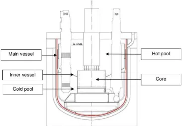
The CFV core thermal power is equal to 1500 MW and all the primary components are included in a main vessel (Figure 1). A single conical “redan” (inner vessel) separates the primary sodium in two areas: the hot pool, filled with sodium at 550 °C from the cold pool, filled with sodium at 400 °C. Three mechanical Primary Pumps (PPs) are immerged in the primary sodium to ensure the sodium circulation from the cold pool to the hot pool by crossing the core. In steady-state operating conditions, the thermal power is extracted from the primary circuit to the secondary circuit through four Intermediate Heat Ex-changers (IHX) (Figure 1).
Figure 1. Primary system arrangement
1 CFV stands for « Cœur à Faible effet de Vidange » in French that means core with low sodium void
Control rods located above the core and maintained by electromagnets control the core reactivity. In case of incidental or accidental transient, once a protection threshold is reached, these rods fall by gravity into the core, inducing a reactor scram. After such a scram, the DHR systems remove decay heat to ensure the safety and the control of the reactor.
1.2. Decay Heat Removal systems
One of the main innovations investigated for the SFR is the enhancement of the reliability of the DHR systems, based on a diversification strategy (Hourcade et al., 2016). In case of LOOP, the standard procedure uses Direct Reactor Auxiliary Cooling Systems (DRACS) named RRB. These systems con-sist in a sodium/sodium heat exchanger located in the hot pool, a sodium circuit and a sodium/air heat exchanger out of the main vessel. The RRB remove the decay heat by natural convection (passive system) and use air as heat sink.
1.3. Secondary circuits
These intermediate circuits remove the heat from the primary circuit and transfer it to the PCS through the IHX and the Sodium Gas Heat Exchangers (SGHE). The secondary side consists in four independ-ent sodium loops, each one being equipped with a mechanical pump. They separate the primary circuit from the PCS in order to reduce the risk of gas inlet in the primary circuit and in the core.
1.4. Power conversion system
The PCS is a closed Brayton cycle, with two compression stages, with pure nitrogen at 180 bar in the high-pressure line (Figure 2). The plant is composed of two shaft lines with a thermal power of 750 MW each. A turbine, a low-pressure compressor, a high-pressure compressor and a generator are placed on the same shaft line and compose a turbine generator set. For normal operating, the gas temperature is decreased down to 27 °C through the two coolers before each compressor inlet to limit the compres-sion work. The pre-cooler is located upstream of the low-pressure compressor and the intercooler is located upstream of the high-pressure compressor. The heat sink is a water flow through the two cool-ers. A so-called recuperator Heat Exchanger (HX) allows gas temperature to raise up before its return to the SGHE. The recuperator HX enhances the net efficiency of the power plant that reaches 37.4% with the Gas-PCS.
For regulation and safety issues, the by-pass 1 line (BP1) (red line on the Figure 2) connects the high-pressure compressor outlet to the pre-cooler inlet. A valve located on this line enables to modify the mechanical balance on the shaft by reducing the gas flow rate through the turbine.
The so-called nitrogen inventory control system called Nitrogen Supply System (NSS) enables to control the nitrogen inventory and consequently to modify the pressure in the PCS. It is composed of a gas extraction line connected to the high-pressure compressor outlet (highest PCS pressure point, blue ar-row on the Figure 2) and a gas injection line connected to the pre-cooler inlet (blue arar-row on the Figure 2).
Figure 2. Sketch of the SFR with a focus on the Gas-PCS
code CATHARE2.
2. CATHARE2 modelling of the reactor
The whole reactor presented in section 1 is modelled with the thermalhydraulic system code CATHARE2 (Geffraye et al., 2011) to study the SFR behavior in case of a LOOP transient.
2.1. CATHARE2 code description
CATHARE2 is a thermalhydraulic system code developed for the last thirty years by the CEA, Electricité de France (EDF), Framatome and the French radioprotection and nuclear safety institute (IRSN). This code, originally devoted to best-estimate transient calculations in pressurized water-cooled reactors, includes six equations (mass, momentum and energy balance for liquid and vapor phases).
The properties of sodium have been implemented, the friction and heat transfer correlations being the same as in the water standard version (Geffraye et al., 2011). In this version of the code, nitrogen gas is considered as an ideal gas.
To compute the neutron power evolution of the core, the following reactivity feedbacks are taken into account: Doppler effect, sodium density, cladding expansion, fuel expansion, hexagonal can expansion, diagrid expansion and finally the reactivity feedback resulting from the relative position of the control rods compared to the core and to the main vessel. All these reactivity coefficients are included in the point kinetics of neutron physics module of CATHARE2 including eight groups of delayed neutrons and four groups of fission products to model the decay heat.
All the computations presented in this article are performed with CATHARE2 v25_3 mod 5.1.
2.2. Input deck content
Primary circuit
The core channels, the IHX, the upstream and downstream of the pumps are modelled as 1-D CATHARE2 axial elements. The flow distribution within the cold and hot pools is modelled thanks to several dedicated 0-D volumes.
Decay Heat Removal systems
The RRB are present in the input deck and modelled by a heat sink. The removed power is considered as a linear function depending of the sodium temperature in the hot pool. This behavior was observed for reactor tests simulating decay heat removal situations performed in Phenix and Superphenix reactors (Tenchine, 2010). The RRB are designed to extract a thermal power of 50 MW for a sodium temperature in the hot pool of 530 °C and an air temperature of 35 °C. According to these assumptions, the heat removed is defined as the equation 1:
𝑄𝐷𝐻𝑅̇ = 50 ∗ 𝑇𝐻−35
530−35 (1)
With:
- 𝑄𝐷𝐻𝑅̇ : Power extracted by the RRB (MW);
- 𝑇𝐻: Hot pool temperature (°C). Power conversion system
The PCS system is fully modelled in the CATHARE2 input deck. Each of the heat exchangers (pre-cooler, inter(pre-cooler, recuperator) is modelled thanks to two axial elements exchanging heat in a counter flow HX. The water flow in the coolers is modelled thanks to boundary conditions (water-inlet tempera-ture fixed to 21 °C, water-feed flow rate respectively fixed to 12000 kg/s and 9000 kg/s for normal oper-ating conditions in the pre-cooler and the intercooler and the water-outlet pressure fixed to one bar). The rotating mass equation is solved on the shaft including the turbine, the compressors and the resist-ing torques of the generator when it is connected to the grid. Comprehensive TM performance maps are provided as input data.
The BP1 by-pass line is modelled thanks to a 1-D axial element and its associated valve can be oper-ated.
For the NSS:
- The extraction line is modelled by an orifice, with a diameter of 10 centimeters, a valve and the gas pressure boundary conditions of 1.013 bar;
- In case of a gas removal, the difference between the high-pressure inside the PCS and the atmospheric conditions induces a choked flow. From the conservation of the mass, the defini-tions of the Mach number and of the sound speed, coupled to the Laplace law and the ideal gas equation of state, a compressible form of the mass flow rate is obtained and given by the equa-tion (2). 𝑄𝑐𝑟= 1 2. 𝜋. 𝐷2 4 . 𝑃𝐶𝐻𝑃. √ 𝑀𝑁2.𝛾 𝑅.𝑇𝐻𝐶𝑃. ( 2 𝛾+1) 𝛾+1 2.(𝛾−1) (2) With: - 𝑄𝑐𝑟: Choked flow (kg/s);
- 𝐷: Diameter of the extraction line section (m);
- 𝑃𝐶𝐻𝑃: Pressure at the outlet of the high-pressure compressor (Pa);
- 𝑀𝑁2: Nitrogen molar mass (Kg/mol);
- 𝛾: Laplace coefficient (ratio of specific heats, 1.4 for diatomic gas); - 𝑅: Ideal gas constant (J/mol/K);
- 𝑇𝐻𝐶𝑃: Temperature at the outlet of the high-pressure compressor (K).
The presented input deck is going to be used to simulate a LOOP transient.
3. The studied procedure and associated multiobjective problem
3.1. The LOOP transient and the alternative procedureThe generator disconnection from the electrical grid and the loss of the electrical supplies of the primary, secondary and heat sink pumps initiate the transient of LOOP. The resisting torque of the generator on the shaft is suddenly decreases to zero and induces a turbomachinery overspeed. The detection of the LOOP transient by the control systems causes the full opening of the by-pass 1 valve, which aims at limiting this overspeed. To save the turbomachinery integrity, its rotation speed must not exceed 3300 rpm. The loss of electrical supplies induces the decrease of the primary and secondary flow rates to 25% of their nominal value in 30 seconds. The water feeding of the coolers is stopped. A few seconds after the Initiating Events (IE), the electromagnets maintaining the control rods are switched off and the reactor scram occurs.
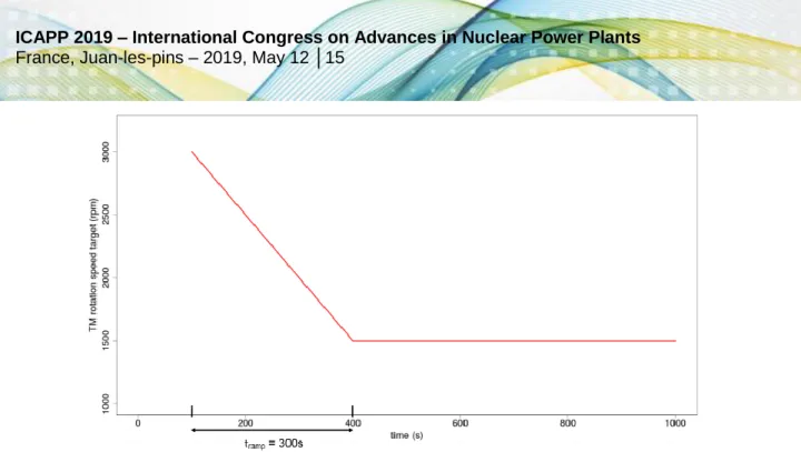
The main issue following the reactor scram is to remove the decay heat. A standard solution is to rely-on passive DRACS like RRB systems described in the sectirely-on 1.2 and modeled in the sectirely-on 2.2. In this paper, an alternative procedure (preliminary studied, Bertrand et al., 2016b) is proposed and substitutes the RRB with the gas PCS to remove the decay heat. After the IE and the first consequences, several actions are required to keep an efficient heat removal with the water heat sink via the gas PCS and the secondary circuit. As for the standard procedure, 30 seconds after the IE, emergency electrical supplies are available to ensure a primary mass flow rate of 25% of its nominal value during the whole transient. Contrarily to the procedure with RRB, 30 seconds after the IE, the secondary pumps are powered by backup systems and the secondary flow rate is maintained at 25% of its nominal value during the whole transient. The feasibility study and the sizing of the emergency supplies associated to the primary and secondary pumps were realized for the European Fast Reactor (EFR, 1999). Few sec-onds after the IE, a backup water flow rate is provided as well in the coolers to ensure the heat removal. Furthermore, the water flow rate regulates the gas inlet temperatures of the two compressors to the setpoint of 27 °C, in order to avoid damages on the compressors and to keep an efficient heat sink. The power provided by emergency supply limits the maximal water flow rate to 40% of its nominal value. For this procedure, the PCS is operated in two different ways. First, it cools the reactor down to reach the cold shutdown state and then, it maintains this safe state. In the first step, the gas flow rate must be strong enough to remove the decay heat and the energy previously accumulated in the sodium; once the cold shutdown state is reached, only the decay heat must be removed to maintain the reactor in a safe state. For this purpose, a regulation of the TM rotation speed, by the BP1 valve, ensures a gas flow. The target of this regulation is time dependent and described by the two parameters (Figure 3):
- A ramp-down period, called tramp, for which the target varies from 3000 rpm to a steady value; - The steady value of the rotation speed after the ramp-down period, called ωsteady.
Figure 3. TM rotation speed target applied for t =100 s; tramp=300 s andωsteady =1500 rpm After a delay depending of the ωsteady value, a too much important cooling than needed occurs and could induce a sodium freezing. The selected solution, to adapt the removed power to the decay heat, is to regulate the sodium temperature, at the SGHX outlet, with the NSS. A 180 °C setpoint is selected to maintain the reactor in the cold shutdown state and the regulation is actuated once the sodium temper-ature at the outlet of the SGHX becomes lower than 180 °C; the corresponding time is called tSGHX. A summary of this alternative procedure is provided in the Table 1.
Table 1. Chronological summary for the standard LOOP and the alternative procedure
Time LOOP with
RRB LOOP with PCS
t = 0s
IE: Generator disconnection from the grid
Beginning of the primary and secondary flow rates decrease Stopping of the coolers water-feeding
t = 1s Turbomachinery protection: full opening of the by-pass 1 valve
t ~ 2s Reactor scram
t = 2s x Regulation of the TM rotation speed
t = 3s x Water feeding of the coolers thanks to backup systems and regulation of the gas temperature at the compressor inlets with water flow rate t =
30s
Primary flow rate fixed to 25% of its nominal value thanks to emergency electrical supplies x Secondary flow rate fixed to 25% of its nominal value thanks to emergency
electrical supplies t =
tRRB
RRB
switch on x
tSGHX x Regulation of the sodium temperature at the SGHX outlet
The regulation of the TM rotation speed relies on a Proportional-Integral-Derivative (PID) corrector. Its setting has been done in a previous study by minimization of the difference between the target and the rotation speed for a LOOP transient. The two other regulations required by the alternative procedure rely-on proportional correctors.
3.2. The associated multiobjective problem
In addition to remove the decay heat, it is interesting to minimize the required time to reach the cold shutdown state of the reactor, in the aim to offer the possibility to act as fast as possible on the reactor. In the present study, this time (called 𝑡𝐶𝑆𝐷) is reached when the temperature of the sodium at the inlet
of the core becomes lower to 210 °C. This state is maintained by the regulation of the sodium tempera-ture at the outlet of the SGHX.
Furthermore, the main vessel has to resist to all stresses during its lifetime and avoid creeping condi-tions. In this aim, thermal stresses induced on the main vessel by thermal gradients have to be as low as possible. These stresses are assessed during a transient by the absolute value of the thermal gradi-ent through the main vessel (equation 3).
With:
𝑔𝑟𝑎𝑑(𝑇) =𝑇𝑖−𝑇𝑜
𝑒 (3)
- 𝑇𝑖: Inside temperature of the vessel (°C);
- 𝑇𝑜: Outside temperature of the vessel (°C);
- 𝑒: main vessel width (4cm).
The thermal gradient is studied at the higher part of the main vessel, where the highest thermal stresses are observed, because of the proximity of the hot pool, which induces a heat-up of the main vessel. Cold sodium flow from the core inlet to an annular space inside and against the main vessel is hence derived to cool down the main vessel. This annular space is called the immersed weir and ensures creep and fatigue resistance of the main vessel. It is at this cooling system that the most significant thermal gradients are observed. In this paper, the two needed temperatures to assess the thermal gra-dient through the vessel are located at the inlet of the immersed weir. In the following, the maximum absolute value of the thermal gradient is the criterion to assess the thermal stresses induced on the main vessel. We defined it as MTG (°C/cm) (equation 4) depending on the thermal gradient given by the equation 3:
𝑀𝑇𝐺 = max (|grad(T)|) (4)
The nominal value of the thermal gradient through the main vessel is equal to 0.5 °C/cm.
The MultiObjective Problem (MOP) solves in this paper is to minimize simultaneously the MTG and the
tCSD for the alternative procedure and a LOOP transient. The decision variables are the two descriptive parameters of the TM rotation speed target (tramp and ωsteady). The resolve of this MOP is presented in the following section.
4. Optimization of the alternative sequence
In this section a research of TM rotation speed targets to optimize simultaneously the two objectives defined in the section 3.2 is performed. The improvements will be presented and a study of the relation-ship between the optimum targets and the two objectives is realized.
4.1. Optimization of two conflicting objectives
In this study, a random search approach is applied to solve the MOP. A set of CATHARE2 code simu-lations defined by different TM rotation speed targets is performed, and the best observed candidate is selected to solve the MOP. To ensure an optimal coverage of the input space an optimized Latin Hy-percube Samples (LHS, optimized by discrepancy criterion, see Fang, 2001 or Damblin et al., 2013 for details) is used.
An optimal LHS including 250 calculations built the database (Carnell, 2018) to cope with the calculating budget. Its inputs are the two parameters of the TM rotation speed target which variation ranges are set in the Table 2.
Table 2: Variation ranges to the exploration of different TM rotation speed target
Lower limit Upper limit
tramp (s) 0 2000
ωsteady (rpm) 1000 2000
The MOP is characterized by two objectives whose variations are conflicting. On the one hand, the tCSD objective decreases significantly with an increase of the ωsteady parameter. On the other hand, the MTG increases with an increase of the tramp parameter. These qualitative variations are observed in the Figure 4, in which each objectives of optimization of the database are plotted in function of the two descriptive parameters of the TM rotation speed target. However, as shown in the Figure 4, the relation between
MTG and ωsteady and the relation between tCSD and tramp are not clear according to this scatterplot anal-ysis. These clear dependences between the outputs and the inputs of the MOP is explained by the required time to reach the objectives. A post-processing of the database shows the required time to reach the peak of thermal stress is included between 5 s and 4610 s with a mean of 1265 s and a
standard deviation of 720 s. The MTG is mainly reached for the tramp period and it explains why the MTG is more sensitive to this parameterthan the ωsteady. The direction of variation is explained; for a fixed
ωsteady, a high tramp period generates for the first part of the transient a higher gas flow rate than a low
tramp, and so increases the cooling of the reactor as well as the thermal stresses on the main vessel. Conversely, the time to reach the cold shutdown state is largely impacted by the final value of the TM rotation speed because the variable tCSD is about several hours and therefore is only slightly impacted by the TM rotation speed decrease occurring at the beginning of the sequence. The higher the ωsteady is, the higher the removed power through the SGHX is and the required time to reach the cold shutdown state decreases with an increase of ωsteady.
Nevertheless, it can be expected according to engineering judgment that for a high ωsteady the MTG cannot be minimal. Indeed, a high ωsteady induces a large TM rotation speed for the tramp period and so a large gas flow rate involving a strong cooling of the structures. In the same way, a small tramp does not induce a short tCSD. In this case, the TM rotation speed and so the gas flow rate are reduced very fast, the time to reach the cold shutdown state would be higher than a case with a high tramp. The two objec-tives are so well conflicting and each objective is more sensitive to a decision variable.
Figure 4. Scatterplot of the two objectives of optimization as functions of tramp and ωsteady For this multiobjective conflicting problem, the two objectives have to be minimized simultaneously, it does not exist an unique but several solutions defining the Pareto set (in the input space: tramp and ωsteady) for which the two associated objectives (tCSD and MTG; output space) define the Pareto front. Each solution of the Pareto front is an optimum compared to transients not included in the front; it means none TM rotation speed target has the property to generate two objectives simultaneously lower than all the members of the Pareto front. Finally, if no preference between the two conflicting objectives is defined, each member of the Pareto front is optimal and is not better than the other members of the Pareto front.
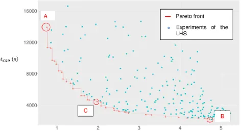
Based on the LHS above-mentioned, the solution of this MOP is the following Pareto front (Figure 5) associated to the Pareto set (Figure 6) constructed with the R package “rPref” (Roocks, 2016). The Pareto front is defined by 35 experiments included between two extremes (Experiments A and B in the Figure 5 and the Figure 6), presented in the Table 3, which define two large ranges of variation for the two objectives of optimization. The alternative procedure allows the reactor to reach the cold shutdown state in the range 30 minutes to 4 hours. A short time to reach the safety state induces a MTG through the main vessel close to 5 °C/cm (“B” experiment), whereas a long time to reach the safety state induces a MTG through the main vessel close to 1 °C/cm (“A” experiment).
The scatterplot above-presented highlights the high dependences between the time to reach the cold shutdown state to the ωsteady parameter and between the thermal stresses on the main vessel to the
tramp parameter. According to these dependences and to the directions of variation, the strong values for
tramp combined to the low values for ωsteady cannot solve the MOP. It should be noticed that by considering
the set of calculations in a graph representing their input parameters tramp as a function of ωsteady an area
defined by a tramp between 500 s and 2000 s and a ωsteady between 1000 rpm and 1875 rpm (delimitated by a red rectangle in the Figure 6) is not included in the Pareto set. To solve the MOP, this input space area won’t be used to define the TM rotation speed target.
Figure 5. Experiments of the database and Pareto front: tCSD=f(MTG)
Figure 6. Experiments of the database and Pareto set: 𝑡𝑟𝑎𝑚𝑝=f(𝜔𝑠𝑡𝑒𝑎𝑑𝑦)
Table 3. Points of interest of the Pareto front
tramp (s) ωsteady (rpm) 𝑡𝐶𝑆𝐷 (s) 𝑀𝑇𝐺 (°C/cm)
A 145 1141 13915 0.7
B 1340 1903 2157 4.7
C 242 1720 4448 1.98
In addition to this optimization, a LOOP transient for which the decay heat is removed thanks to in-vessel heat exchanger as modelled in the section 2.2 is performed. For this procedure, the MTG is equal to 3.3 °C/cm and twenty-four hours after the initiating events the cold shutdown state is not achieved. The procedure based on the gas PCS offers some advantages compared to the procedure with in-vessel heat exchanger. The cold shutdown state is reached and the thermal stresses on the main in-vessel can be reduced. Furthermore, the optimization of the alternative procedure allows the operating to min-imize simultaneously these two objectives. The following part presents the combinations of the decision variables to define an experiment included in a specific area of the Pareto front.
4.2. Analyze of the Pareto front
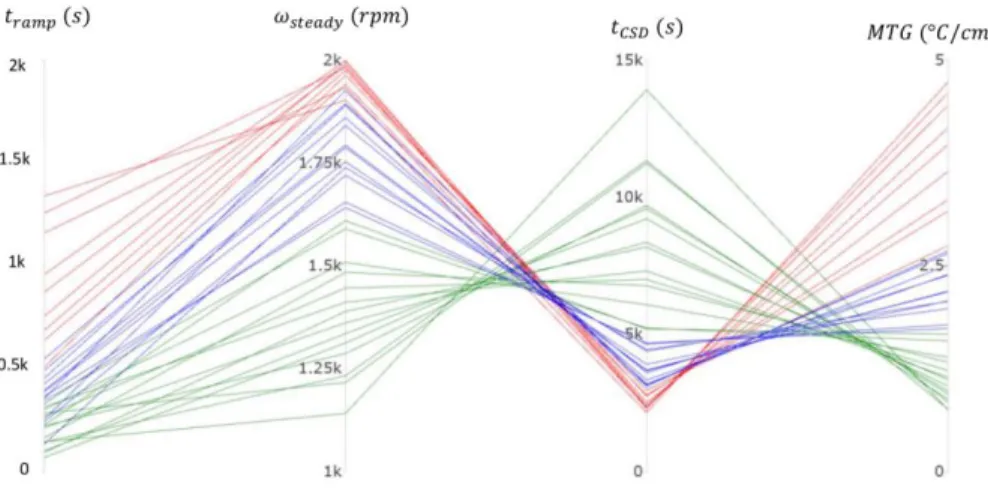
To understand the relations between the decision variables and the optimized objectives a cobweb plot of experiments included in the Pareto front is a useful tool. This one associated to the Pareto front defined in Figure 5 is built with the R package "plotly" (Carson, 2018) and presented in the Figure 7. and penalizing the other (one objective is close to the minimum observed in the set of simulations, whereas the other objective reaches a high value). These parts are characterized by the fact that a small improvement in an objective causes a large degradation for the other objective.
Figure 7. Cobweb plot of the Pareto front
The Pareto front can be arbitrarily separated in three parts.
- The first part is built with elements that favor the MTG and penalize the tCSD: the tCSD is higher than 5000 s and the MTG lower than 1.6 °C/cm (green lines in the Figure 7). These transients required a low tramp combined to an ωsteady inferior to 1600 rpm, in the aim to reduce as low as possible the tCSD without increasing too much the MTG. The point A of the Table 3 is included in this part.
- The second part presents elements that favor the tCSD and penalize the MTG: this one is lower than 3000 s and the MTG higher than 2.8 °C/cm (red lines in the Figure 7). These transients required an ωsteady superior to 1930 rpm necessarily combined to a tramplonger than 500 s, to reduce as low as possible the MTG without increasing significantly the tCSD. The point B of the Table 3 is included in this part.
- The third part includes optimal compromises for which the tCSD value is included between 3000 s and 5000s, and the MTG value is included between 1.6 °C/cm and 2.8 °C/cm (blue lines in the Figure 7).
The two first parts (green and red lines in the Figure 7) can be qualified as compromises privileging one of the two objectives of optimization and penalizing the other (one objective is close to the minimum observed in the set of simulations, whereas the other objective reaches a high value). These parts are characterized by the fact that a small improvement in an objective causes a large degradation for the other objective.
Based on these observations an analyze of the Pareto set is provided. An objective of optimization is privileged by selecting a specific domain for the decision variable that impacts the most this objective. For instance, to have a low MTG, a low tramp is needed (points A and C). Then, the penalized objective can be improved without deteriorating significantly the privileged objective by adapting the decision var-iable that influents the most the penalized objective. For instance, the experiment C favors the MTG objective with a low tramp (tramp = 242 s) and with a ωsteady of 1720 rpm the tCSD is reduced to 4448 s. Another possibility is to define the decision variable that affects the most the penalized objective to degrade it and to favor the privileged objective. For instance, the experiment A penalizes the tCSD to allow the MTG objective to be as low as possible by fixing the ωsteady to 1141 rpm.
To conclude, the TM rotation speed targets as defined in the Table 2 offers a great diversity of compro-mises to solve the MOP defined in the section 3.2. To favor a specific objective, it is necessary to choose
the decision variable that affects the most this objective in a specific range.
Conclusion and perspectives
This paper presents an alternative sequence, in case of the LOOP accident, removing the decay heat with the gas PCS instead of exploiting the in-vessel DHR systems. The three regulations required to operate the cooling of the reactor are:
- The regulation of the TM rotation speed to keep an efficient gas flow;
- The regulation of the sodium temperature at the outlet of the SGHX, to adapt the heat removal to the decay heat, once the cold shutdown state is reached;
- The regulation of the gas temperature at the inlet of the compressors of the PCS, to keep an efficient heat sink.
The alternative procedure in case of the LOOP accident is efficient to reach the cold shutdown state and to maintain it, whereas it is not possible with the RRB for the same scale of time. The PCS, thanks to the regulation of the TM rotation speed with the BP1 valve, is an adaptable system to optimize sim-ultaneously the two conflicting objectives:
- The time to reach the cold shutdown state; - The thermal stresses on the main vessel.
The definition of the time dependent TM rotation speed target with two parameters (tramp and ωsteady) and the explored variation ranges offer the possibility to define a great diversity of optimum compromises. Furthermore, the high dependences between an objective to a specific parameter of the TM rotation speed target offer the possibility to favor one objective by choosing the parameter that affects the most this objective in a specific range.
The Pareto front, associated to this MOP, has been determined and it groups all the optimum compro-mises. It is up to designers to choose among the Pareto front which transients are the more interesting for them. On the one hand, it is possible to decrease the maximum of the thermal gradient through the main vessel up to 0.7 °C/cm by accepting a time to reach the cold shutdown state equal to 4 hours. On the other hand, it is possible to decrease the time to reach the cold shutdown state up to 30 minutes by accepting the maximum of the thermal gradient through the main vessel to be close to 4.7 °C/cm. With a maximum of the thermal gradient equal to 3.3 °C/cm, for the procedure with in-vessel DHR systems, it is highlighted that this alternative procedure can reduce the stresses on the main vessel.
Another interesting objective to optimize would be the period for maintaining the reactor in the safe state. The longer this period is the latter the in-vessel DHR systems could be actuated. This possibility is interesting to improve safety by keeping for a long time a diversification of the systems to perform the DHR function.
This study is a first step towards a methodology to optimize the reactor operation in case of various transients. To finalize the methodology, other tools have to be chained to the building of LHS and Pareto front. The latter would be able to define, for a specific transient and a MOP, the procedures to obtain the best compromises.
References
Bertrand F. et al., 2016a; Comparison of the behaviour of two core designs for ASTRID in case of severe acci-dents; Nuclear Engineering and Design, Vol. 297, February 2016, Pages 327-342.
Bertrand F. et al., 2016b; Transient behavior of ASTRID with a gas power conversion system; Nuclear Engineer-ing and Design, Vol. 308, August 2016, Pages 20-29.
Carnell. 2018. lhs: Latin Hypercube Samples. R package version 0.16. https://CRAN.R-project.org/package=lhs Carson, 2018; Plotly for R. https://plotly-book.cpsievert.me
Chenaud M.S. et al., 2013; Status of ASTRID core design studies at the end of predesign phase 1; Nuclear Engi-neering and Technology, Vol. 45, N°6.
Damblin G., Couplet M., Bertrand I, 2013; Numerical studies of space-filling designs: Optimization of Latin Hyper-cube Samples and subprojection properties. Journal of Simulation. 7. 10.1057/jos.2013.16.
EFR Non Site Specific Safety Report, Framatome/Novatome, 1999
Fang K.-T., 2001; Wrap-around L2-discrepancy of random sampling, Latin hypercube and uniform designs, Jour-nal of Complexity 17, pp 608-624.
Geffraye G. et al., 2011. CATHARE 2 V2.5_2: A single version for various applications, Nuclear Engineering and Design, Vol. 241, Issue N°11, November 2011, Pages 4456-4463.
Hourcade E. et al., 2016. ASTRID Nuclear Island design: advances in French-Japanese joint team development of Decay Heat Removal systems, Proceedings of ICAPP, San Francisco, USA, April 17-20, 2016
Nuclear Energy Agency. 2016. GIF Annual report. 2016.
Roocks Patrick. 2016. rPref: Database Preferences and Skyline Computation. R package version 1.2. https://CRAN.R-project.org/package=rPref
Tenchine D., 2010. Some thermal hydraulic challenges in sodium cooled fast reactors, Nuclear Engineering and Design, Vol. 240, Issue N°5, May 2010, Pages 1195-1217.
Nomenclature
D Diameter of the NSS extraction line section (m) 𝛾 Laplace coefficient
𝑚𝑁2 Nitrogen mass in the PCS (kg)
𝑀𝑁2 Nitrogen molar mass (g/mol)
MTG Maximum absolute value of the thermal gradient through the main vessel (°C/cm) 𝜔 Rotation speed of the TM (rpm)
ωsteady Steady value of the TM rotation speed target (rpm)
𝑃𝐻𝐶𝑃 Pressure at the outlet of the high-pressure compressor (Pa)
𝑄𝑐𝑟 Choked flow (kg/s)
𝑄𝐷𝐻𝑅̇ Power removed by the RRB (MW)
𝑅 Ideal gas constant (J/mol/K)
t Time (s)
tCSD Time to reach the cold shutdown state of the reactor since the initiating event of the
LOOP (s)
𝑡𝑟𝑎𝑚𝑝 Ramp-down period, during which the TM rotation speed target varies from 3000 rpm
to a steady value (s)
tRRB Time for which the RRB are switched on (s)
tSGHX Time for which the regulation of the sodium temperature at the outlet of the SGHX is
actuated (s)
𝑇𝐻𝐶𝑃 Temperature at the outlet of the high-pressure compressor (K)
𝑇𝑖 Vessel inside temperature (°C)
𝑇𝑜 Vessel outside temperature (°C)
𝑇𝑜𝑆𝐺𝐻𝑋 Temperature of the sodium at the outlet of the SGHX (°C)
Glossary
BP1 Specific By-Pass line interlinking the high-pressure compressor outlet to the pre-cooler inlet
CFV core Low void worth core DHR Decay Heat Removal
DRACS Direct Reactor Auxiliary Cooling System EFR European Fast Reactor
GIF Generation IV International Forum IE Initiating Event
(I)HX (Intermediate) Heat Exchangers LHS Latin Hypercube Sampling LOOP Loss Of Off-site Power
MOP Multiobjective Optimisation Problem NSS Nitrogen Supply System
PCS Power Conversion System PID Proportional-Integral-Derivative PP Primary Pump
RRB Passive DHR systems with a heat exchanger in the hot pool SGHE Sodium Gas Heat Exchangers
SFR Sodium-cooled Fast Reactor TM Turbomachinery