HAL Id: hal-02319736
https://hal.archives-ouvertes.fr/hal-02319736
Submitted on 13 Apr 2021
HAL is a multi-disciplinary open access
archive for the deposit and dissemination of
sci-entific research documents, whether they are
pub-lished or not. The documents may come from
teaching and research institutions in France or
abroad, or from public or private research centers.
L’archive ouverte pluridisciplinaire HAL, est
destinée au dépôt et à la diffusion de documents
scientifiques de niveau recherche, publiés ou non,
émanant des établissements d’enseignement et de
recherche français ou étrangers, des laboratoires
publics ou privés.
Polythermal diagrams of aqueous boundary ternary
systems involving sodium borohydride hydrolysis for
hydrogen generation
T. Vilarinho-Franco, R. Chiriac, R. Tenu, J.J. Counioux, J. Delmas, P.
Capron, C. Goutaudier
To cite this version:
T. Vilarinho-Franco, R. Chiriac, R. Tenu, J.J. Counioux, J. Delmas, et al.. Polythermal diagrams of
aqueous boundary ternary systems involving sodium borohydride hydrolysis for hydrogen generation.
Fluid Phase Equilibria, Elsevier, 2018, 460, pp.189-197. �10.1016/j.fluid.2017.12.014�. �hal-02319736�
1
Polythermal diagrams of aqueous boundary ternary systems
involving sodium borohydride hydrolysis for hydrogen generation
T. Vilarinho-Franco
1,2,3*, R. Chiriac
2, R. Tenu
2, J.J. Counioux
2, J. Delmas
3, P. Capron
3,
C. Goutaudier
21 Intelligent Energy, Charnwood Building, Holywell Park, Ashby Road, Loughborough Leicestershire, LE11 3GB, United Kingdom 2 Université de Lyon, Université Claude Bernard Lyon 1, Laboratoire Multimatériaux et Interfaces, UMR CNRS 5615, 69622 Villeurbanne cedex,
France
3 Commissariat à l’Energie Atomique et aux Energies Alternatives de Grenoble (CEA), 17, Rue des Martyrs 38054 Grenoble cedex 9, France
* Corresponding author. Tel - 33 (4) 38786009. E-mail: tatiana.vilarinho@intelligent-energy.com Keywords: solid-liquid equilibria, polythermal diagrams, DSC applied to ternary mixtures
Abstract
The comprehension of solid-liquid equilibria involved in the quaternary system NaBH4–NaBO2–NaOH–H2O allows
us to follow the evolution of mixtures during the sodium borohydride hydrolysis reaction for hydrogen generation. The addition of sodium hydroxide on saturated solutions of sodium borohydride and metaborate have been studied in a temperature range of –10 °C up to 50 °C which is the operational temperature range of a hydrogen generator for consumer electronics application. The solubility data was monitored at low temperatures by Differential Scanning Calorimetry, DSC analyses. Given the large number of solid phases that may crystallize in a stable or metastable state, the definition of a specific protocol was required in order to evaluate a ternary mixture via DSC analyses presenting a good repeatability. The nature of different solid phases present in this system was confirmed by powder X-ray analyses. Finally, two polythermal diagram outlines of aqueous boundary ternary systems involving water, sodium borohydride, sodium hydroxide and sodium borate were proposed. The results obtained in the water-rich area show that the sodium hydroxide hydrates are relatively soluble and the risk of precipitation is mainly due to the sodium borohydride dihydrate (NaBH4.2H2O) and sodium metaborate tetrahydrate (NaBO2.4H2O). The
crystallization areas were defined as function of temperature and composition.
1. Introduction
For several years now, the hydrogen generation via hydrolysis of sodium borohydride is considered as having a real technological potential for consumer applications, as presented by Demirci in an overview article with over 280 references about this technology, highlighting the scientific and technical critical points of the hydrogen cycle via sodium borohydride hydrolysis [1].
NaBH4 has been attracting distinct interest because of its high gravimetric percentage of hydrogen, 10.8 w% of
hydrogen released by hydrolysis [2]. NaBH4 alkaline solution can be transported safely and this hydrolysis reaction
provides hydrogen with a good purity [3-6]. In aqueous solution, however, the hydrogen generation via sodium borohydride hydrolysis presents a major drawback concerning its by-products, hydrated sodium borate compounds in a saturated solution of sodium metaborate, NaBO2.yH2O, with pseudo hydration degree y = 0, 1/3, 2/3, 2 or 4 [7].
This metaborate hydrate formation significantly modifies the density and viscosity of the solution during hydrolysis reaction.
One of the main challenges to improve the energy density of this hydrogen generator system, is to increase the NaBH4 concentration in aqueous solution, thus avoiding the drawback induced by metaborate saturated solution and
2
consequently metaborate hydrate precipitation in the operation temperature range of the system i.e. around ambient conditions.
Sodium borohydride decomposes spontaneously in water to produce hydrogen and by-products: hydrated sodium borate compounds. Sodium hydroxide is added to the solution to limit this self-decomposition, thus stabilizing the system [8], but the aqueous solution of sodium borohydride can be stabilized by making it alkaline through the addition of hydroxide ions, generally sodium hydroxide (NaOH) [5, 9, 14, 18]. In these conditions the aqueous solutions of stabilized sodium borohydride are particularly well adapted to on-board applications, because they provide a high volumetric storage capacity.
The optimization of key operational parameters of this portable hydrogen generator is directly linked to the hydrolysis reaction yield as a function of the initial concentration of sodium borohydride, operational temperature as well as a function of by-product hydrates and final solution solubility [10]. Therefore, the delimitation of the homogeneous liquid phase domain in the phase diagram quaternary system NaBH4–NaBO2–NaOH–H2O is
fundamental.
In order to understand the behavior of the aqueous solution of sodium borohydride hydrolysis, the main challenge is to describe the solid-liquid equilibria involved in the quaternary system NaBH4–NaBO2–NaOH–H2O, which
represents the evolution of the mixture during the hydrolysis reaction. In a previous work, the solubility limit of the hydrolysis’s by-products, NaBO2.yH2O, has been investigated and the experimental results for the solubility limit in
the ternary system NaBO2–NaOH–H2O under ambient pressure at 10, 25 and 50 °C have been presented [11]. In this
present work, polythermal diagrams of the two aqueous boundary ternaries NaBH4-NaOH-H2O (corresponding to
0 % of hydrolysis reaction conversion) and NaBO2–NaOH–H2O (100 % of conversion) will be proposed from
critical analysis of the description of several isotherm sections of each system [11-14] and will be completed by DSC analysis with the intent to give more precision about invariant transformations of the system. The third aqueous boundary ternary system NaBH4–NaBO2–H2O cannot be experimentally evaluated because of the spontaneous
decomposition of NaBH4 in water, i.e. without hydroxide as a stabilizer. The quaternary mixture NaBH4–NaBO2–
NaOH–H2O corresponds to the hydrolysis solution itself, and will be published subsequently as a subject of a
thorough experimental work.
In favor of a good comprehension of the complexity of these two aqueous boundary ternary systems, NaBH4–
NaOH–H2O and NaBO2–NaOH–H2O, three well-known aqueous boundary binary systems, NaBO2–H2O [7, 15-17];
NaBH4–H2O [14, 18] and NaOH–H2O [19] have been also taken into account. Note that the binary system NaBH4–
H2O needs to be stabilized (NaOH as stabilize agent) in order to avoid Sodium borohydride spontaneous
decomposition in water (see Table 1).
The Tables 1, 2 and 3 list the invariant transformations of each aqueous binary system. The three-phase equilibria are depicted on cooling direction, by convention.
Table 1. Invariant transformation in the binary system NaBH4–H2O (stabilize agent NaOH 0.1 mol.L-1) [14, 18] at ambient pressure.
T [°C] w % NaBH4 Transformation Equilibrium –37.5 21.8 eutectic (ei) Liquid ⇋ Ice + NaBH4.2H2O
3
Table 2. Invariant transformation in the binary system NaOH–H2O (stable or metastable) [19] at ambient pressure.
T [°C] w% NaOH Transformation Solid phases in equilibrium –28.7 18.6 stable eutetic (e1) Ice + NaOH.7H2O
–24.0 22.3 stable peritectic (p1) NaOH.7H2O + NaOH.5H2O
–18.0 24.7 stable peritectic (p2) NaOH.5H2O + α-NaOH.4H2O
5.1 32.4 stable peritectic (p3) -NaOH.4H2O + 2NaOH.7H2O
–1.3 35.7 metastable fusion -NaOH.4H2O 15.9 38.8 congruent fusion (fc1) 2NaOH.7H2O
–2.7 37.2 metastable eutectic β-NaOH.4H2O + NaOH.3H2O 2,6 42.5 metastable fusion NaOH.3H2O
46.8 6.2 stable eutectic (e2) 2NaOH.7H2O + NaOH.2H2O
3.0 48.5 metastable eutectic 2NaOH.7H2O + NaOH.H2O 12.9 50.5 Stable peritectic (p4) NaOH.2H2O + NaOH.H2O
65.1 68.9 congruent fusion (fc2) NaOH.H2O
62.0 74.0 stable eutectic (e3) NaOH.H2O + α-NaOH
297.0 96.8 stable phase transition α-NaOH + β-NaOH Table 3. Invariant transformation in the binary system NaBO2–H2O [7] at ambient pressure.
T [°C] w % NaBO2 Transformation Equilibrium
–7.0 ± 2.0 12.3 eutectic (ei) Liquid ⇋ Ice + NaBO2.4H2O 55.0 ± 2.0 37.2 peritectic (pi) Liquid + NaBO2.2H2O ⇋ NaBO2.4H2O 103.5 ± 0.2 52.6 peritectic (pii) Liquid + 3NaBO2.2H2O ⇋ NaBO2.2H2O 131.6 ± 0.2 58.7 peritectic Vapor + 3NaBO2.2H2O ⇋ Liquid 163.2 ± 0.2 84.6 peritectic Vapor + 3NaBO2.H2O ⇋ 3NaBO2.2H2O 260.0 ± 0.7 91.6 peritectic Vapor + NaBO2 ⇋ 3NaBO2.H2O
After the review of the ternary systems, differential scanning calorimetry (DSC) analyses were carried out in ternary aqueous mixtures in order to complete data and more particularly the temperature of some feature invariant transformations. Differential scanning calorimetry (DSC) is a commonly technique used to study and characterize thermal phenomena in complex media. As an example, Reyes-Labarta et al. applied DSC analyses to evaluate transitions and reactions undergone by polymers, such as melting, crystallization, and reordering in their structure [20]. Although, it is important to consider the complexity of DSC analyses concerning ternary mixtures, the transitions phenomena are dependent of the temperature scanning protocol and the proper calibration of DSC in order to attempt accurate results and a good repeatability.Powder X-ray diffraction analyses were performed for the structural identification of the solid phases present in some crystallization domains.
4
2. Material and Methods 2.1. Ternary mixture preparation
For the ternary mixture preparation, anhydrous NaOH (Sigma-Aldrich®, ≥ 99.99 % purity, pellets, n° CAS: 1310-73-2) is stored and handled in an argon-filled glove box in order to prevent hydration. Deionized water is introduced at room temperature. Commercial sodium borate, NaBO2.yH2O (ACROS Organics, 98.5 % purity, n° CAS:
10555-76-7) is submitted to heat treatment in order to obtain the anhydrous NaBO2. In this latter case, commercial borate
(mixture of NaBO2.4H2O and NaBO2.2H2O) is heated at 300 °C for 72 hours in a tubular oven under argon flow.
Afterwards, anhydrous borate is confirmed by powder X-ray diffraction analysis. 2.2. Differential scanning calorimetry (DSC) Analysis
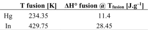
Thermal analyses by DSC were performed to determine the ternary invariant transformations at low temperatures. The tests were performed on a differential scanning calorimeter DSC820 (Mettler-Toledo), under nitrogen with a flow of 30 mL.min-1. The calibration of the DSC equipment in terms of heat flow and temperature and tau lag was
done by using the theoretical values of enthalpies and melting temperatures of two metal standards: mercury (Hg) and indium (In), for which the precise values of enthalpies and melting temperatures are well known (see Table 4). After the experimental determination of DSC at two increasing temperature rate 0.5 K.min-1 and 5.0 K.min-1, the
errors do not exceed 0.1 % and 1.0 % for temperature and enthalpy values, respectively. The difference between the temperature of set point and the actual temperature measured on the sample was 0.02 K maximum. The software used to run the acquisition and to exploit the results was 9.20 STAR (Mettler-Toledo).
Table 4. Metal standards temperature and fusion enthalpy. T fusion [K] ΔH° fusion @ Tfusion [J.g–1]
Hg 234.35 11.4
5
DSC analyses applied to ternary mixtures exhibit a certain complexity particularly when the mixtures are viscous. It is the case in the NaBO2–NaOH–H2O system. In order to avoid the phenomenon of major segregation between the
solid phases able to crystallize, the rapid cooling leads to the quenching of the solution. The definition of a protocol for temperature scanning in order to have repeatability demands much attention. To support this statement figure 1 reveals a thermogram with two consecutive runs and exemplifies the lack on repeatability concerning the phase transformation phenomena in the ternary mixture NaBO2–NaOH–H2O, exemplifying a non-reproducible thermogram
and illustrating the difficulty encountered during the DSC measurements of the studied mixtures which are very viscous. It is clear that the thermograms on Fig.1 are not usable. This is why many trials have been necessary to achieve a protocol leading to reproducible results. The selected protocol is presented in Figure 2 and has been successfully to determine the invariant phenomena presented in this work.
Figure 1. DSC thermogram of an aqueous ternary mixture M (24.8 w% NaOH - 5.16 w % NaBO2-70.04w% H2O) first results underscoring
no repeatability on the phase transformation phenomena.
Figure 2 illustrates the protocol of the temperature scanning profile of the DSC analyses. A sample of the aqueous ternary mixture M (39.03 mg) was introduced in a hermetic 120 L stainless steel pan and then placed into the DSC cell. A combination of a rapid cooling rate (10 K.min-1) to obtain a stable crystallization and a very slow heating rate
(1 K.min-1) for endothermic events was finally defined after many tests at different cooling and heating rates. Indeed
the determination of temperature of the equilibria is highly dependent of the kinetics. Three consecutive run analyses were then performed using this defined protocol in order to verify results repeatability.
Figure 2. Temperature scanning profile adopted for DSC analyses.
6
In order to determine the crystallization domain in the polythermal diagrams, PXRD analyses were performed on the Bruker D8 Advance diffractometer, in air and at room temperature.
This diffractometer has a Bragg-Brentano configuration, used in reflection mode, with a θ-2θ installation and a copper anticathode tube (λ Kα1 = 1.5406 Å - λ Kα2 = 1.54439 Å). The sample is prepared by removing some solid phase from the diphasic solution. The solid mixture sample is then dried with a filter paper at ambient temperature and atmospheric pressure. Then the sample is placed on a specific holder. A 50 m Kapton® is used to prevent hydration and CO2 capture of the solid during sample handling and analysis. It is important to note that the solid
phase is impregnated with saturated solution, and thus the spectrum background can be significant. To obtain an exploitable spectrum, the PXRD experiment time is about 2h for each experimental solid mixture in order to minimize the spectrum background.
3. Discussions on polythermal diagram of the ternary system NaBH4-NaOH-H2O | Literature data critical
analyses
In a first step, a critical analysis of solubility data as a function of temperature from the literature was performed with the intent to give a qualitative representation of the polythermal diagrams for the NaBH4–NaOH– H2O and NaBO2–
NaOH– H2O systems.
In a second step, a series of experimental investigations by XRD and DSC analysis was carried out in order to confirm the qualitative representation, to validate the nature of the crystallized solid phases present in different domains and to specify the characteristics of the invariant transformations.
The representation of a polythermal diagram consists of projecting the isothermal invariant points in the composition plane. One line connecting these points fixes the limits of two crystallization fields. The variance of these lines, which are only function of the temperature, is equal to 1. The intersection of two monovariant lines constitutes an invariant equilibrium point. The composition of the corresponding liquid phase, in equilibrium with three solid phases is independent of temperature at a given pressure.
Figure 3 shows the superposition of isothermal sections of the ternary system NaBH4–H2O–NaOH at –10 °C
determined by Churikov et al. [12] and at 0, 18 and 30 °C determined by Mikheeva and Breitsis [14] also illustrated by Shang and Chen [21]. The graphic on Figure 3 highlights the solid phase domains of different ternary invariant points of each isotherm. It also presents the temperature of the two invariant transformation of the binary system NaBH4–H2O (eutectic at –37.5 °C and a peritectic at 36.4 °C) and the temperature of the lower stable eutectic of the
7
Figure 3. Superposition of the isotherms at –10, 0, 18 and 30 °C of the ternary system NaBH4–H2O–NaOH. Literature data from Churikov et al.
[12] and Mikheeva and Breitsis [14].
Two monovariant lines can be drawn from these results illustrated at Figure 3: a first monovariant line connecting the points (1), (3), (5) and (7) which are invariant points of a three-phases equilibrium: liquid+NaBH4.2H2O+NaBH4;
and a second one connecting the invariant points (2), (4), (6) and (8) of a three-phases equilibrium: liquid+NaOH.H2O+NaBH4.
Figure 4 presents the polythermal diagram of the ternary system NaBH4–NaOH–H2O with the two aqueous binary
systems located on the edge: NaBH4–H2O and NaOH–H2O. Figure 4 also illustrates the projection of the invariants
points (from 1 to 8 illustrated on Figure 3) on the composition plane of the two invariant lines just mentioned previously. Figure 4 depicts an extra invariant point from the isotherm at 50 °C of the ternary system NaBH4–
NaOH–H2O determined by Mikheeva and Breitsis [14], integrating the second monovariant line. This picture
8
Figure 4. Polythermal representation of the ternary system NaBH4–NaOH–H2O, invariants points from isotherms at –10, 0, 18, 30 and 50 °C [12,
14] with the aqueous boundary binary systems on the edge: NaOH–H2O [19] and NaBH4–H2O [14, 18].
The intersection resulting from the extrapolation to lower temperatures of the two monovariant lines (based on experimental results from the literature, Figure 4) allows us to estimate the composition of the invariant liquid phase
0
as: 9.0 w% NaBH4, 40.0 w% NaOH and 51.0 w% NaOH. All other ternary invariants like1, 1, eqb2, 3, 4
and
2
presented on the polythermal diagram outline are an attempt towards a representation based on thermodynamics and phase diagrams theory, respecting the rules of polythermal diagrams construction.Figure 5a illustrates, firstly, the isobaric binary invariant transformations (represented by
■
on the axis) from which start the ternary monovariant lines and secondly, the intersections of these curves which result in eight ternary invariant transformations:0, 1, 1, eqb2, 3, 4 and 2
all reported in Table 5.The intersection of the two monovariant lines based on experimental results from the literature, extrapolated to lower temperatures, defines the invariant liquid phase
0
in equilibrium with 3 solid phases: NaBH4, NaBH4.2H2O andNaOH.H2O (see Figure 5a). The associate transformation is a transitory peritectic type, i.e., each composition point
is composed by three solid phases and a liquid phase, each point is located in a convex quadrilateral. Figure 5b schematizes the four-phase equilibrium corresponding to the peritectic transformation between the liquid
0
and the solid NaBH4, NaBH4.2H2O and NaOH.H2O. Under constant pressure condition, the variance is zero, so the9
Figure 5a. Polythermal diagram of the ternary system NaBH4-NaOH-H2O with isobaric binary invariant transformations (■), different hydrates
(▲). Definition of different domains of crystallization with the isobaric invariants points. Proposition of monovariant lines based on literature data: isotherm at –10 °C by Churikov et al. [12] and isotherms at 0, 18, 30 and 50 °C by Mikheeva and Breitsis [14].
An interesting observation is the isoplethic section NaBH4.2H2O–NaOH.7/2H2O which is indicated by a dashed blue
line that intersects the monovariant line pi–
0 to point Z, at TZ temperature. This isoplethic section explains whybelow TZ temperature, the isoplethic section provides a quasi-binary behavior, i.e., it behaves like a binary system,
more precisely; all tie-lines are in the plane of this section.
As a conclusion, the schematic polythermal diagram of the ternary system NaBH4–NaOH–H2O presented on Figure
5a is speculative, and the position of certain invariant points could be slightly different in the quantitative diagram. Accurate determination of the latter implies the knowledge of the compositions and temperatures of isobaric invariant transformations whose study remains to be done.
10
Figure 5b. Representation of the convex quadrilateral involving Ʈ 0, transitory peritectic transformation.
Table 5. Isobaric ternary invariant transformations of the system NaBH4–NaOH–H2O. The four-phase equilibria are represented on cooling
direction, by convention.
Point Transformation Equilibrium
Ʈ 0
Transitory peritectic Liquid Ʈ 0 + NaBH4 ⇋ NaBH4.2H2O + NaOH.H2O
Ʈ 1 Transitory peritectic Liquid Ʈ
1 + NaOH.H2O ⇋ NaBH4.2H2O + NaOH.2H2O
Ɛ1 Eutectic
Liquid Ԑ 1 ⇋ NaOH.2H2O + 2NaOH.7H2O +NaBH4.2H2O
Ʈ 2 Transitory peritectic Liquid
Ʈ 2 + 2NaOH.7H2O ⇋ NaBH4.2H2O + NaOH.4H2O
Ʈ 3 Transitory peritectic Liquid Ʈ3+ NaOH.4H2O ⇋ NaBH4.2H2O + NaOH.5H2O
Ʈ 4 Transitory peritectic Liquid Ʈ4 + NaOH.5H2O ⇋ NaBH4.2H2O + NaOH.7H2O
Ɛ 2 Eutectic Liquid Ԑ 2 ⇋ Ice + NaBH4.2H2O + NaOH.7H2O
Ɛ eqb Quasi-binary eutectic Liquid Ԑ eqb ⇋ NaBH4.2H2O + 2NaOH.7H2O
4. Experimental results
4.1 NaBH4-NaOH-H2O solid phase characterization of solid crystallization domain
An outline of the complete polythermal diagram of the ternary system NaBH4-NaOH-H2O at low temperature is
proposed in the composition plane on Figure 5a. The proposed polythermal diagram is built based on few experimental results from the literature and on thermodynamics rules guiding the monovariant lines. All proposed
11
monovariant lines define different crystallization domains and solid phases likely to occur in the ternary system: ice; NaOH.7H2O; NaOH.5H2O; NaOH.4H2O; NaOH.7/2H2O; NaOH.2H2O; NaOH.H2O; NaBH4.2H2O and NaBH4.
Arrows at the monovariant lines indicate the direction of lower temperatures.
The crystallization domains of ice, NaBH4.2H2O and anhydrous NaBH4 are much broader than those of NaOH with
higher hydrates. The precipitation domain of NaOH.2H2O is not well defined because of the inaccuracy of the
position of the line dividing the crystallization domains of NaOH.2H2O and anhydrous NaOH.
Figure 6 present the experimental results of PXRD of a mixture located on the crystallization domain of the sodium borohydride dihydrate, NaBH4.2H2O (mixture point composition: 25 w% NaBH4; 10 w% NaOH and 65 w% H2O).
The comparison of the experimental pattern with the ICDD file n° 00-036-1233 confirms the solid phase domain of NaBH4.2H2O. Effectively, X-ray diffractograms show a large continuous background and low intensity diffraction
peaks. This is related to the fact that they are recorded on wet solids. In order to maintain the equilibrium state of the solid phase, some stock solution must be retained. However, there is no ambiguity in the identification of the solid phase in comparison with the ICDD files.
Figure 6. Powder X-Ray pattern of solid phase of the crystallization domain of borohydride superior hydrate: NaBH4.2H2O, ICDD file n°
00-036-1233 represented in red (mixture point composition: 25 w% NaBH4; 10 w% NaOH and 65 w% H2O).
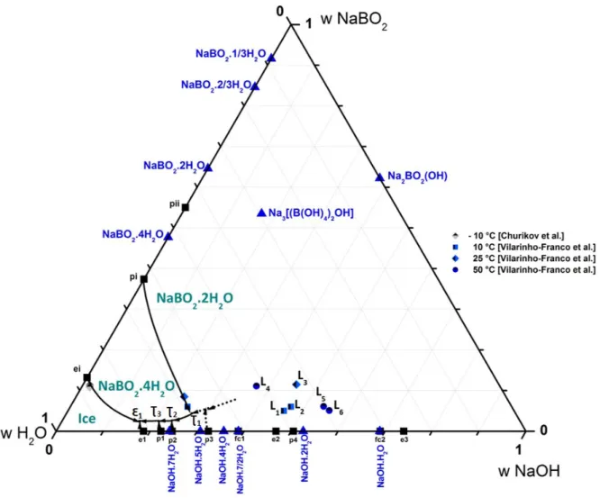
4.2 NaBO2-NaOH-H2O polythermal diagram proposition (based on experimental data from this author’s previous
work)
After the experimental work on isothermal of the ternary system NaBO2–NaOH–H2O published previously [11] an
outline of polythermal diagram is proposed for this ternary system in Figure 7. The proposed monovariant lines are based on experimental results from the literature. It shows the invariant points from isotherm at –10 °C determined by Churikov et al. [12] and from isothermal at 10, 25 and 50 °C determined in previous work [11]. This polythermal diagram consists of eight invariant or monovariant lines fairly well defined (solid lines) and three hypothetical lines drawn in dot lines. The monovariant lines delimitated the crystallization domains of ice, metaborate tetrahydrate NaBO2.4H2O, metaborate dihydrate NaBO2.2H2O, and superior hydrates of sodium hydroxide NaOH.7H2O,
12
The compound Na2BO2(OH) (ICDD reference 00-037-0114) mentioned in Figure 7 can be written in the form of a
double compound NaOH.NaBO2 or in more general system of oxides as 2Na2O.B2O3.H2O. Compound Na2BO2(OH)
equilibrium with a liquid phase had never been observed before and the determination of its solubility is unprecedented. The structure of the compound Na2BO2(OH) was defined by Menchetti and Sabelli in 1982 [22].
Structural analysis of the double compound leading to the formula Na3[(B(OH)4)2OH] was performed by the author
in a previous publication [11].
These monovariant lines intersect each other to give five isobaric invariant transformations. Figure 7 illustrates four of these isobaric invariant transformations
1,
2,
3,
1
, reported in Table 6. All the solid phases listed in the literature regarding the ternary system NaBO2–NaOH–H2O are represented in Figure 7, although some are notinvolved in the equilibria studied.
Figure 8 presents the experimental PXRD patterns of a mixture located on the crystallization domain of the sodium metaborate tetrahydrate, NaBO2.4H2O (mixture point composition: 15 w% NaBH4; 10 w% NaOH and 75 w% H2O).
The comparison of the experimental pattern with the ICDD file n° 04-011-5978 confirms the solid phase of NaBO2.4H2O.
Figure 7. Polythermal diagram of the ternary system NaBO2–NaOH–H2O with binary invariant temperatures (■), different hydrates (▲).
Definition of different domains of crystallization with the isobaric invariants points. Proposition of monovariant lines: isotherm at –10 °C by Churikov et al. [12] and isothermal at 10, 25 and 50 °C from previous experimental work [11].
13
Figure 8. Powder X-Ray pattern of solid phase of the crystallization domain of metaborate superior hydrate: NaBO2.4H2O, ICDD file n°
04-011-5978 represented in red (mixture point composition: 15 w% NaBH4; 10 w% NaOH and 75 w% H2O).
4.3. Temperature determination of ternary invariant points of the system NaBO2-NaOH-H2O. DSC analyses
In order to accurately determine the temperature of the ternary invariants, a suitably chosen mixture sample M (24.8 w% NaOH and 5.16 w% NaBO2) located in the triangle of solid-phases NaBO2.4H2O–NaOH.7H2O–
NaOH.5H2O was prepared and then analyzed by DSC.
Figure 9 illustrates a close-up of the polythermal diagram already presented in the previous Figure 7. This close-up shows the position of the mixture point M (purple) and the path followed by the liquid phase during cooling (in orange). The path starts from point M and continues toward the monovariant line Ʈ1Ʈ2 (on the tie-line NaBO2.4H2
14
Figure 9. Close-up of polythermal diagram of the ternary system NaBO2–NaOH–H2O presented in Figure 8, mixture point M (24.8 w% NaOH
and 5.16 w% NaBO2) sample located on solid-phase domain of NaBO2.4H2O and in the triangle of solid-phases NaBO2.4H2O–NaOH.7H2O–
NaOH.5H2O.
Figure 10 depicts the superposition of three consecutive DSC runs for the point mixture M. These curves are perfectly superimposable, presenting a very significant exothermic peak corresponding to the crystallization of species with temperature around –65 °C (onset) during the first heating. This peak is no longer manifested in the second heating attesting complete crystallization of the sample M. Three other endothermic peaks (surrounded by dotted line) appear during heating at temperatures remarkably reproducible. These three endothermic peaks were enlarged in Figure 10 (a) and (b). Temperature scanning protocol adopted for DSC analysis was presented in Figure 2.
15
Figure 10. DSC thermograms presenting three consecutive run analyses for mixture sample M, the temperature range: –80 °C to 25 °C. (a) zoom on the two last overlapped endothermic peaks; (b) zoom on the first endothermic peak.
Considering the path followed by the sample (mixture M) during a slow cooling that serves the mixture to reach equilibrium, it is possible to observe two partially overlapping peaks between –13 and –22 °C corresponding to two neighboring transitional transformations Ʈ2 and Ʈ3. Both transformations are close enough to the intersection point of
the corresponding line NaBO2.4H2O-M with the monovariant lineƮ2Ʈ3. Due to its location on the ternary diagram,
the mixture M contains a large quantity of liquid phase with respect to solid phase, which explains the large amount of heat from this transformation; see Figure 10 (a). Their specific onset temperature determined by the intersection of the downward straight portion of peaks with the baseline, are respectively equal to –17.7 ± 0.2 °C for the ternary invariant Ʈ2 and –20.4 ± 0 2 °C for the invariant Ʈ3.
Figure 10 (b) shows the first endothermic peak, much less intense than the previous. It is due to the disappearance of solid phase ice at the isobaric ternary eutectic transformation Ɛ1 which explains the lower peak intensity caused by
the reduction of the amount of material in this transformation. The ternary eutectic onset temperature of this was estimated to be –35.2 ± 0.2 °C. All results concerning the temperatures determinate by DSC analyses are summarized in Table 6.
The analyses of the evolution of monovariant lines led to propose four isobaric ternary invariants better defined, i.e. a ternary eutectic Ɛ1 and three transitional transformations Ʈ1; Ʈ 2; Ʈ3 and Ʈ4. The corresponding transition reactions are
given in Table 6.
Table 7 presents the equilibrium of invariant points L1 to L6 from previous experimental results of isothermal at 10, 25 and 50°C illustrated at polythermal diagram on Figure 7.
16
Table 6. Isobaric ternary invariant transformations of the ternary system NaBO2–NaOH–H2O.
Experimental results of temperature of three isobaric invariant transformations determined by DSC analyses. Point T [°C] Transformation Equilibrium
Ʈ1 – transitory peritectic Liquid Ʈ 1 + NaBO2.2H2O ⇋ NaBO2.4H2O + NaOH.4H2O
Ʈ 2 –17.7 transitory peritectic Liquid Ʈ 2 + NaOH.4H2O ⇋ NaBO2.4H2O + NaOH.5H2O
Ʈ 3 –20.4 transitory peritectic Liquid Ʈ 3 + NaOH.5H2O ⇋ NaBO2.4H2O + NaOH.7H2O
Ɛ 1 –35.2 eutectic Liquid Ԑ 1 ⇋ Ice + NaBO
2.4H2O + NaOH.7H2O
Table 7. Equilibrium of invariant points L1 to L6 from previous experimental results of isothermal at 10, 25 and 50 °C illustrated at polythermal
diagram on Figure 7.
Isotherm temperature [°C] Invariants points Equilibrium
10 L1 Liquid ⇋ NaBO2.2H2O + Na3[(B(OH)4)2OH]
L2 Liquid ⇋ Na3[(B(OH)4)2OH] + NaOH.H2O
25 L3 Liquid ⇋ NaBO2.2H2O + NaOH.H2O
50
L4 Liquid ⇋ NaBO2.2H2O + 3NaBO2.H2O
L5 Liquid ⇋ 3NaBO2.H2O + Na2BO2(OH)
L6 Liquid ⇋ Na2BO2(OH) + NaOH.H2O
5. Conclusion
The phase equilibria study of aqueous boundary ternary system NaBH4–NaOH–H2O and NaBO2–NaOH–H2O was
undertaken. A polythermal diagram of each ternary system was proposed according to experimental solubility data of these systems and their subsystems. Ternary system solubility data consider previous work from the author [11] and other authors [12-14].
A critical literature data review and analysis allowed the proposition of two polythermal diagram outlines including the definition of monovariant lines, several invariants transformations and, consequently, the definition of different crystallization domains from low temperatures up to 50 °C. Furthermore, powder XRD analyses have confirmed the nature of the solid phases present in different crystallization domains. At the end of this study, it was possible to clearly established that the risk of precipitation in these two ternary systems are primarily due to sodium metaborate hydrates and sodium borohydride hydrate, whose crystallization domains are fairly well-defined in the polythermal diagrams.
In the area of low concentration sodium borohydride or sodium metaborate solutions, all hydrates of the sodium hydroxide may be observed in a stable state below 50 °C. In this temperature range, the sodium borohydride and its hydrate, NaBH4.2H2O, present a stable equilibrium with the liquid phase.
The proposed polythermal diagram outline regarding the ternary system involving the hydrolysis by-product final solution, NaBO2–NaOH–H2O, was completed by DSC analyses in order to characterize, qualitatively, the nature of
17
NaBO2.4H2O and NaBO2.2H2O can easily precipitate in a stable state, although the inferior hydrates, NaBO2.2/3H2O
and NaBO2.1/3H2O present metastable equilibria, which explains the necessity to establish an appropriate heat
treatment during DSC analyses in order to obtain repeatable results. Moreover, the presence of double compounds presenting stable and metastable behavior, as Na2BO2(OH) or Na3[(B(OH)4)2OH] – discovery in a previous work,
also emphasize the importance of a specific temperature scanning protocol for the application of DSC analysis to evaluate these ternary mixtures.
Acknowledgments
This research was supported by CEA-Liten (Commissariat à l’Energie Atomique et aux Energies Alternatives) and Université de Lyon, Université Claude Bernard Lyon 1, LMI department. We thank our colleagues from both institutions who provided insight and expertise that greatly assisted the research work.
References
[1] Demirci U.B. The hydrogen cycle with the hydrolysis of sodium borohydride: A statistical approach for highlighting the scientific/technical issues to prioritize in the field. Int. J. of Hydrogen Energy. 2015; 40: 2673–2691.
[2] [Laversenne, L. Goutaudier C., Chiriac R., Sigala C., Bonnetot B. Hydrogen storage in borohydrides: Comparison of hydrolysis conditions of LiBH4, NaBH4 and KBH4. J. Therm. Anal. Calorim. 2008; 94: 785–790.
[3] Minkina V. G., Shabunya S.I., Kalinin V. I., Martynenko V. V., Smirnova A. L., Long–term stability of sodium borohydrides for hydrogen Generation. Int. J. Hydrogen Energy. 2008; 33: 5629–5635.
[4] Çakanyildirim Ç. and Gürü M. Hydrogen cycle with sodium borohydride. Int. J. Hydrogen Energy. 2008; 33: 4634–4639. [5] Liu B.H., Li Z.P. A review: Hydrogen generation from borohydride hydrolysis reaction. J. of Power Sources. 2009; 187: 527–534.
[6] Damjanović L., Bennici S., Auroux A. A direct measurement of the heat evolved during the sodium and potassium borohydride catalytic hydrolysis. J. of Power Sources. 2010; 195: 3284–3292.
[7] Andrieux J., Laversenne L., Krol O., Chiriac R., Bouajila Z., Tenu R., Counioux J.J., Goutaudier C. Revision of the NaBO2–H2O phase
diagram for optimized yield in the H2 generation through NaBH4 hydrolysis. Int. J. of Hydrogen Energy. 2012; 37: 5798–5810.
[8] Andrieux J., Demirci U. B., Hannauer J., Gervais C., Goutaudier C., Miele P. Spontaneous hydrolysis of sodium borohydride in harsh conditions. Int. J. of Hydrogen Energy. 2011; 36: 224–233.
[9] Suda S., Sun Y. M. Liu B.H. Zhou Y., Morimitsu S., Arai K., Tsukamoto N., Uchida M., Candra Y., Li Z. P. Catalytic generation of hydrogen by applying fluorinated-metal hydrides as catalysts. Applied Physics A. 2001; 72: 209–212.
[10] Vilarinho-Franco T., Tenu R., Delmas J., Heitzmann M., Capron P., Goutaudier C. Lifetime analysis of a hydrogen generator by hydrolysis of sodium borohydride. Energy Procedia. 2013; 36: 1192–1201.
[11] Vilarinho-Franco T., Tenu R., Teyssier A., Pécaut J., Delmas J., Heitzmann M., Capron P., Counioux J.J., Goutaudier C. Solid-Liquid Equilibria in the ternary system NaBO2–NaOH–H2O. Fluid Phase Equilibria. 2013; 360: 212–221.
[12] Churikov A. V., Zapsis K. V., Khramkov V. V., Churikov M. A., Smotrov M. P., Kazarinov I. A. Phase Diagrams of the Ternary Systems NaBH4-NaOH-H2O, KBH4-KOH-H2O, NaBO2-NaOH-H2O and KBO2-KOH-H2O at −10 °C. J. Chem. Eng. Data. 2011; 56: 9–13.
[13] Churikov A. V., Zapsis K. V., Khramkov V. V., Churikov M. A., Gamayunova I. M. Temperature–Induced Transformation of the Phase Diagrams of Ternary Systems NaBO2-NaOH-H2O and KBO2-KOH-H2O. J. Chem. Eng. Data. 2011; 56: 383–389.
[14] Mikheeva V. I. and Breitsis V. B. Temperature variation of solubility in the NaBH4–H2O system and solubility isotherms at 0°, 18°, 30° and
50° C for the NaBH4–NaOH– H2O system. Russian J. Inorg.Chem. 1960; 5: 1234–1238.
[15] Nies N. P. and Hulbert R. W. Solubility isotherms in the system sodium oxide-boric oxide-water. Revised solubility–temperature curves of boric acid, borax, sodium pentaborate, and sodium metaborate. J. Chem. Eng. Data. 1967; 12: 303–313.
[16] Tolédano P. and Benhassaïne A., presented by Champetier G. Sur un appareil d’analyse thermique différentielle sous pression. Etude du système métaborate de sodium-eau, Comptes Rendus de l'Académie des Sciences de Paris. 1970; série C: 1577–1580.
[17] Dukelski M. Z. Anorg. Chem. 1906; 50: 38-48.
[18] Jensen E.H. A study on sodium borohydride with special reference to its analytical application in organic chemistry, Copenhagen : Nyt. Nordisk Forlag. 1954; 219.
[19] Rollet A.P and Cohen-Adad R. Les systèmes eau-hydroxyde alcalin Revue Chimie Minérale. 1964; 1: 451.
[20] Reyes-Labarta J.A., Olaya M. M. and Marcilla A. DSC study of transitions involved in thermal treatment of foamable mixtures of PE and EVA copolymer with azodicarbonamide. J. Appl. Polym. Sci. 2006; 102: 2015–2025.
[21] Shang Y. and Chen R. Hydrogen Storage via the Hydrolysis of NaBH4 Basic Solution: Optimization of NaBH4 Concentration. Energy &
Fuels. 2006; 20: 2142–2148.
![Table 1. Invariant transformation in the binary system NaBH 4 –H 2 O (stabilize agent NaOH 0.1 mol.L -1 ) [14, 18] at ambient pressure.](https://thumb-eu.123doks.com/thumbv2/123doknet/12860898.368541/3.892.210.722.882.969/table-invariant-transformation-binary-nabh-stabilize-ambient-pressure.webp)
![Table 3. Invariant transformation in the binary system NaBO 2 –H 2 O [7] at ambient pressure](https://thumb-eu.123doks.com/thumbv2/123doknet/12860898.368541/4.892.174.750.694.907/table-invariant-transformation-binary-nabo-h-ambient-pressure.webp)


![Figure 4. Polythermal representation of the ternary system NaBH 4 –NaOH–H 2 O, invariants points from isotherms at –10, 0, 18, 30 and 50 °C [12, 14] with the aqueous boundary binary systems on the edge: NaOH–H 2 O [19] and NaBH 4 –H 2 O [14, 18]](https://thumb-eu.123doks.com/thumbv2/123doknet/12860898.368541/9.892.154.784.160.736/figure-polythermal-representation-ternary-invariants-isotherms-aqueous-boundary.webp)