DOI 10.1007/s00190-011-0484-9 O R I G I NA L A RT I C L E
GPS-derived orbits for the GOCE satellite
Heike Bock · Adrian Jäggi · Ulrich Meyer ·Pieter Visser · Jose van den IJssel · Tom van Helleputte · Markus Heinze · Urs Hugentobler
Received: 27 September 2010 / Accepted: 10 May 2011 / Published online: 26 May 2011 © Springer-Verlag 2011
Abstract The first ESA (European Space Agency) Earth
explorer core mission GOCE (Gravity field and steady-state Ocean Circulation Explorer) was launched on 17 March 2009 into a sun-synchronous dusk–dawn orbit with an exception-ally low initial altitude of about 280 km. The onboard 12-channel dual-frequency GPS (Global Positioning System) receiver delivers 1 Hz data, which provides the basis for pre-cise orbit determination (POD) for such a very low orbiting satellite. As part of the European GOCE Gravity Consor-tium the Astronomical Institute of the University of Bern and the Department of Earth Observation and Space Systems are responsible for the orbit determination of the GOCE satellite within the GOCE High-level Processing Facility. Both quick-look (rapid) and very precise orbit solutions are produced with typical latencies of 1 day and 2 weeks, respectively. This article summarizes the special characteristics of the GOCE GPS data, presents POD results for about 2 months of data, and shows that both latency and accuracy requirements are met. Satellite Laser Ranging validation shows that an accu-racy of 4 and 7 cm is achieved for the reduced-dynamic and kinematic Rapid Science Orbit solutions, respectively. The validation of the reduced-dynamic and kinematic Precise Sci-ence Orbit solutions is at a level of about 2 cm.
H. Bock (
B
)· A. Jäggi · U. MeyerAstronomical Institute of the University of Bern, Sidlerstrasse 5, 3012 Bern, Switzerland
e-mail: [email protected]
P. Visser· J. van den IJssel · T. van Helleputte Department of Earth Observation and Space Systems,
Delft University of Technology, Kluyverweg 1, 2629 HS Delft, The Netherlands
M. Heinze· U. Hugentobler
Institut für Astronomische und Physikalische Geodäsie, Technische Universität München, Arcisstraße 21, 80333 Munich, Germany
Keywords GOCE· GPS · Precise orbit determination · SLR validation
1 Introduction
The Gravity field and steady-state Ocean Circulation Explorer (GOCE, Drinkwater et al. 2006) is the first Earth explorer core mission of the European Space Agency (ESA). It was launched on 17 March 2009 from Plesetsk, Russia. The core instrument is a three-axis gradiometer for determin-ing the gravity field with an unprecedented accuracy of 1 mGal and the geoid with an accuracy of 1 cm, both at a spatial resolution of 100 km (Rummel et al. 2002). In addition, the mission is equipped with two 12-channel dual-frequency Lagrange (Intelisano et al. 2008) GPS (Global Positioning System) SSTIs (satellite-to-satellite tracking instruments) consisting of an independent receiver and antenna each. The main unit (SSTI-A) is running in nom-inal operations, whereas the other one serves as a redundant unit (SSTI-B). The results discussed subsequently were all obtained from 1 Hz data of the SSTI-A in the time interval from 31 October 2009 until 10 January 2010 (72 days).
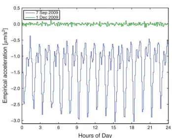
The satellite’s low altitude (259.6 km, mean distance from the geocenter minus the Earth radius at the equator or 254.9 km, mean semi-major axis minus the Earth radius at the equator) is necessary to be highly sensitive to the Earth’s gravity field. This low orbital altitude can only be main-tained with a drag-free flight realized by the drag-free and attitude control system (DFACS). Drag-free flight means for GOCE that the non-gravitational forces acting on the satel-lite in flight direction (mainly atmospheric drag) are com-pensated by an IPA (ion propulsion assembly). Figure1 illus-trates the drag-free mode by means of empirical accelerations (constrained 6 min piece-wise constant) in the along-track
0 3 6 9 12 15 18 21 24 −3.0 −2.5 −2.0 −1.5 −1.0 −0.5 0.0 0.5 Empirical acceleration [ µ m/s 2] Hours of Day 7 Sep 2009 1 Dec 2009
Fig. 1 Empirical along-track accelerations for 2 days; 7 September
2009: descent phase without drag compensation; 1 December 2009: drag-free mode
direction estimated from a reduced-dynamic (RD) orbit determination for 2 days. On 7 September 2009, the satellite was still in its descent phase (Jäggi et al. 2010) to the mea-surement altitude and the drag-free mode was not activated on this day. On 1 December 2009, however, the IPA was activated for the drag-free flight. The differences in the esti-mated accelerations are obvious. The figure also illustrates how well the DFACS works. Not only the mean along-track acceleration is compensated, but also the variations are sig-nificantly reduced. The drag-free flight implies that it is not necessary to use models for the atmospheric drag in the RD orbit determination (see Sect.4.1).
Precise orbit determination (POD) for the GOCE satel-lite is one task of the GOCE High-level Processing Facility (HPF,Koop et al. 2006). A low latency orbit product, the so-called Rapid Science Orbit (RSO), is produced under the responsibility of the Department of Earth Observation and Space Systems (DEOS), Delft University of Technology, The Netherlands. The requirement is a latency of 1 day after availability of GOCE data, and an accuracy of 0.5 m (3D,Visser et al. 2006). The Precise Science Orbit (PSO) is produced at the Astronomical Institute of the University of Bern (AIUB), Switzerland. The requirement in latency is 2 weeks with an accuracy of 2 cm (1D,Visser et al. 2006). The two institutions have proven their ability for LEO POD in, e.g.,Jäggi et al.(2007,2009);van den IJssel et al.(2003); Montenbruck et al.(2005,2008) and have shown inBock et al.(2007) andVisser et al.(2009) that the POD require-ments for the GOCE mission can be met with their proce-dures.
General GOCE GPS data processing information is pro-vided in Sect.2, typical characteristics of the GOCE GPS data
are described in Sect.3, and first GOCE orbit results for the 72-day period are presented in Sect.4. Section5addresses the orbit validation with independent Satellite Laser Ranging (SLR) measurements and Sect.6summarizes the results.
2 General information about GOCE GPS data processing
The estimated GOCE orbits refer to the center of mass (CoM) of the satellite, which requires precise knowledge of the offsets of the corresponding antenna with respect to this CoM and of the attitude of the satellite. Detailed informa-tion about all antenna offsets may be found inBigazzi and Frommknecht(2010). A short summary of this information is provided in this article. Figure2shows a schematic view of the GOCE satellite with the locations of the SSTI-A and SSTI-B antennas, the laser retro reflector (LRR) and the def-inition of the right-handed satellite reference frame (SRF). Due to fuel consumption, the CoM will be slightly moving during the lifetime of the satellite. Table1gives the coordi-nates of the CoM in the SRF for the time interval considered here. Table2lists the coordinates for the center of the mount-ing plane (CMP) of the SSTI-A antenna in the SRF.
XSRF ZSRF OSRF reflector CoM SSTI-A antenna SSTI-B antenna
Fig. 2 Schematic view on SSTI antennas and LRR on GOCE
Table 1 Excerpt of the time series for the CoM coordinates in SRF
Date XSRF(m) YSRF(m) ZSRF(m)
18 May to 29 November 2009 2.5000 0.0036 0.0011 30 November 2009 to 10 January 2010 2.5010 0.0036 0.0011
Table 2 Coordinates of CMP of SSTI-A antenna in SRF
XSRF(m) YSRF(m) ZSRF(m)
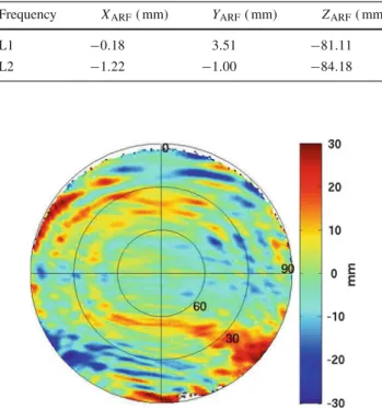
Table 3 SSTI-A antenna PCOs in ARF
Frequency XARF( mm) YARF( mm) ZARF( mm)
L1 −0.18 3.51 −81.11
L2 −1.22 −1.00 −84.18
Fig. 3 Azimuth-elevation diagram of the 1◦× 1◦ PCVs ( mm) for the ionosphere-free linear combination of the GOCE SSTI-A antenna; antenna-fixed system, azimuth of 0◦nominally points into flight direc-tion
Jäggi et al.(2009) showed that neglected or mismodeled antenna phase center offsets (PCOs) and variations (PCVs) are important systematic error sources in GPS data process-ing of LEO satellites. Table3 summarizes the PCO values for the two GPS frequencies in the antenna reference frame (ARF). The axes of the ARF used here are parallel to those of the SRF, but with the origin in the CMP of the SSTI-A antenna. Figure3 shows the 1◦× 1◦ PCVs of the GOCE SSTI-A antenna for the ionosphere-free linear combination of the two GPS frequencies in an azimuth-elevation diagram. The azimuth angle of 0◦ coincides with the x-direction of the ARF/SRF and nominally points into flight direction. The PCVs are the result of an in-flight calibration performed with the so-called residual approach (Jäggi et al. 2009). Carrier phase residuals of the ionosphere-free linear combination from 154 days within April to September 2009 from the RD PSO orbit determination have been used for this purpose. For a more detailed description we refer toBock et al.(2011). The SSTI-A antenna PCVs are consequently used in the PSO procedure (see Sect.4.2). The corresponding numerical val-ues of the PCVs (in ANTEX format,Rothacher and Schmid 2010) as well as the entire time series of the CoM coordi-nates (listed with one digit less than in Table1 orBigazzi and Frommknecht(2010)) can be found athttp://earth.esa. int/GOCE/.
3 GOCE GPS data characteristics
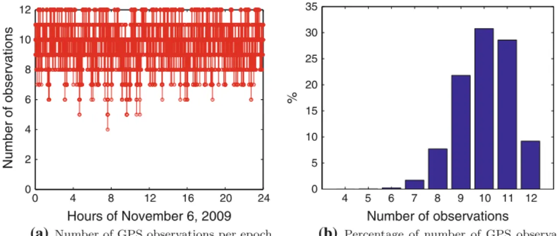
For the first time, 1 Hz GPS data on 12 channels are available for POD of a gravity field mission. The officially available data sets for both CHAMP (Reigber et al. 2002) and GRACE (Tapley et al. 2004) only provide 0.1 Hz on a maximum of ten channels (see, e.g.,Bock 2004). Thanks to the larger num-ber of tracked satellites, more observations are available per epoch, which is very helpful, in particular for the kinematic (KIN) positioning of the GOCE satellite.
Figure4a shows the number of dual-frequency observa-tions per epoch and Fig. 4b the corresponding percentages for a typical day (6 November 2009) extracted from the cor-responding RINEX (Gurtner 1994) file. Ten or more obser-vations per epoch are available for about two-thirds of the epochs. In addition, the GOCE GPS data are hardly affected by data gaps. Only five observation epochs are missing during the entire 72-day period. Before data screening, fewer than 2‰ of the epochs do not have enough (i.e., <5) observations to provide a reliable KIN position estimate.
Time tagging of the observations is a special characteris-tic of the GOCE GPS data. In principle, the observations are sampled at a 1 Hz rate, but the internal clock is not steered to integer seconds and the observation epochs have, therefore, fractional offsets. Figure5a shows these fractional offsets for the midnight epochs of the 72-day period. The fractional offset stays constant for about 25–27 h and then jumps by 20 ms (Fig.5b). The offset had moved by 1 s after 60 days.
These non-steered observation epochs cause no problem in a precise point positioning (PPP,Zumberge et al. 1997) mode, provided the GPS orbit and clock information is calcu-lated at the correct time tags. If the GOCE observations are, however, used together with other observations, e.g., GPS ground tracking data for double- or triple-difference process-ing, a method has to be found to synchronize the observa-tions (see Sect.4.1). The resulting KIN positions from both the RSO and the PSO product are not truly equidistant due to the free running clock. This has to be taken into account when using these KIN positions for further processing, e.g., for gravity field recovery (Jäggi et al 2011).
4 Orbit generation and results
4.1 Low latency orbits: RSO
An RSO chain (Visser et al. 2009;Bock et al. 2007) was implemented for the GOCE satellite to support mission oper-ations. These orbits are used amongst others for external cal-ibration, geodetic preprocessing of the gradiometer data and for quick-look gravity field modeling. The RSO chain pro-vides two orbit types, an RD and a KIN orbit. In addition, the RSO product contains the observation residuals of both
0 4 8 12 16 20 24 0 2 4 6 8 10 12 Hours of November 6, 2009 Number of observations 4 5 6 7 8 9 10 11 12 0 5 10 15 20 25 30 35 Number of observations % (a) (b)
Fig. 4 GOCE GPS dual-frequency observations on 6 November 2009 from RINEX file
Nov 1 Nov 15 Dec 1 Dec 15 Jan 1 0.0 0.2 0.4 0.6 0.8 1.0 Date in 2009/2010 [s]
Nov 4 Nov 5 Nov 6
0.72 0.74 0.76 Date in 2009 [s] (a) (b)
Fig. 5 Fractional offsets of GOCE GPS observation epochs at midnight
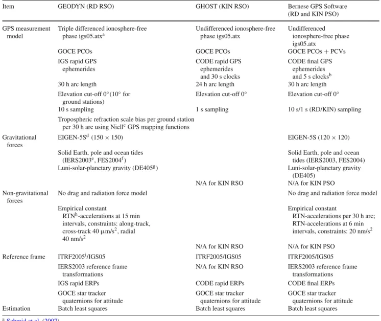
orbits, quaternion information describing the rotation of the Earth centered fixed orbit to the Earth centered inertial frame, as well as a quality report with information about the accu-racy of both orbits. A summary of the dynamical and mea-surement models used for the orbit determination is listed in Table4.
The processing strategy used to obtain the RD RSO is largely based on existing POD infrastructure used at DEOS for CHAMP and GRACE, which is described in detail invan den IJssel et al.(2003). The core of this infrastructure is the GEODYN software, kindly provided by the NASA Goddard Space Flight Center (Pavlis et al. 2006). The POD strategy is based on a triple-difference approach and uses ionospheric-free GPS phase observations along with rapid GPS orbits computed by the International GNSS Service (IGS, Dow et al. 2009). The orbits are computed using 30 h batches, with 6 h overlaps between subsequent orbits. The resulting RSO, however, is cut to daily 24 h solutions and contains position and velocity information with a 10 s sampling. Due to the fractional offsets of the GOCE GPS observations to the inte-ger second (see Sect.3), a simple splines interpolation is used to interpolate the GPS phase observations to integer seconds. The resulting 1 Hz data is down-sampled to 30 s, which is
the data rate of the ground station network used in the triple-differencing scheme. This network consists of 35 more or less homogeneously distributed IGS ground stations. Due to the drag-free flight of the GOCE satellite, no a priori non-gravitational force models are applied; 15 min piece-wise constant empirical accelerations are estimated in three orbital directions instead to account for DFACS residuals and remaining model errors. Due to latency requirements, no use is made of the gradiometer common-mode accelerations.
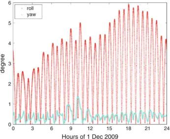
The KIN orbit is computed using the GHOST software, which was developed at the Deutsches Zentrum für Luft- und Raumfahrt in close cooperation with DEOS (van Helleputte 2004). The POD strategy is based on an undifferenced approach, using rapid GPS orbits and 30 s clock corrections computed by the Center for Orbit Determination in Europe (CODE,Dach et al. 2009). This approach was already suc-cessfully used for POD of, e.g., MetOp-A (Montenbruck et al. 2008). The KIN orbit processing is done in 24 h batches and the resulting orbit consists of position information only, with a 1 s sampling. Both the RD and the KIN RSO use attitude information from the star tracker quaternions. Figure6shows the deviations between the actual and the nominal roll- and yaw axes for an example day. The deviations for the pitch
Table 4 Summary of dynamical and measurement models employed for the orbit determination of GOCE
Item GEODYN (RD RSO) GHOST (KIN RSO) Bernese GPS Software
(RD and KIN PSO) GPS measurement
model
Triple differenced ionosphere-free phase igs05.atxa Undifferenced ionosphere-free phase igs05.atx Undifferenced ionosphere-free phase igs05.atx
GOCE PCOs GOCE PCOs GOCE PCOs+ PCVs
IGS rapid GPS ephemerides CODE rapid GPS ephemerides and 30 s clocks CODE final GPS ephemerides and 5 s clocksb
30 h arc length 24 h arc length 30 h arc length
Elevation cut-off 0◦(10◦for ground stations)
Elevation cut-off 0◦ Elevation cut-off 0◦
10 s sampling 1 s sampling 10 s/1 s (RD/KIN) sampling
Tropospheric refraction scale bias per ground station per 30 h arc using NiellcGPS mapping functions Gravitational
forces
EIGEN-5Sd(150× 150) EIGEN-5S (120× 120)
Solid Earth, pole and ocean tides (IERS2003e, FES2004f)
Solid Earth, pole and ocean tides (IERS2003, FES2004) Luni-solar-planetary gravity (DE405g) Luni-solar-planetary gravity
(DE405) N/A for KIN RSO N/A for KIN PSO Non-gravitational
forces
No drag and radiation force model No drag and radiation force model Empirical constant
RTNh-accelerations at 15 min intervals, constraints: along-track, cross-track 40µm/s2, radial 40 nm/s2
Empirical constant
RTN-accelerations per 30 h arc; RTN-accelerations at 6 min intervals, constraints: 20 nm/s2 N/A for KIN RSO N/A for KIN PSO
Reference frame ITRF2005i/IGS05 ITRF2005/IGS05 ITRF2005/IGS05
IERS2003 reference frame transformations
N/A for KIN RSO IERS2003 reference frame transformations
IGS rapid ERPs CODE rapid ERPs CODE final ERPs
GOCE star tracker quaternions for attitude
GOCE star tracker quaternions for attitude
GOCE star tracker quaternions for attitude Estimation Batch least squares Batch least squares Batch least squares
aSchmid et al.(2007) bBock et al.(2009) cNiell(1996) dFörste et al.(2008) eMcCarthy and Petit(2004) fLyard et al.(2006) gStandish(1998)
hRadial, tangential, normal iAltamimi et al.(2007)
axis are not shown, because they are similar to those of the roll axis. The attitude of the GOCE satellite is controlled by magneto-torquers only. The satellite is piloted in yaw-steer-ing mode, which allows the yaw angle (deviations of pitch and roll axes from nominal) to accumulate up to 6◦ at the
equator. These variations are larger than for CHAMP and GRACE, which show variations of 2 and 1◦, respectively.
During the 72-day period considered in this article, PCV maps have not been applied in the RSO processing, since this was not required for meeting the 50 cm 3D accuracy
require-6 5 4 3 2 1 0 0 3 6 9 12 15 18 21 24 Hours of 1 Dec 2009 roll yaw degree
Fig. 6 Absolute deviations between the actual and nominal roll- and
yaw axes of the GOCE satellite for 1 December 2009
Nov 1 Nov 10 Nov 20 Dec 1 Dec 10 Dec 20 Jan 1 Jan 10 0 5 10 15 20 Date 2009/2010 RMS (cm) radial along cross 3D
Fig. 7 RMS values (cm) in radial, along-track, cross-track and 3D for
differences between RD and KIN RSO; 31 October 2009 to 10 Jan-uary 2010; mean offsets: radial 1.44, along-track−0.35, cross-track −3.96 cm
ment. All processing standards are summarized in the GOCE Standards document (ESA 2010b).
Figure7shows the comparison between the RD and the KIN RSO. In general, the internal consistency is around 10 cm (3D). The largest differences occur in cross-track direction, due to the large effects of the PCVs (Fig.3) in this direction (see also,Bock et al. 2011). A big outlier is visible from 3 to 8 December 2009, with orbit differences of up to 47 cm. Around this time, the CODE rapid clock cor-rections were not available (Dach 2009), instead rapid IGS clock corrections were used in the KIN RSO processing. Due to the reduced 5 min sampling of the IGS rapid clock product compared to the 30 s sampling of the rapid CODE clock cor-rections, the accuracy of the KIN solutions is greatly affected by the required interpolation, especially in the radial direc-tion. Other outliers are due to occasional sub-optimal data editing of the KIN orbits.
Figure8gives an overview of the RSO product latency for the entire 72-day period. For most days, the RSO product is available around 12 h after the availability of the GOCE data,
Nov 1 Nov 10 Nov 20 Dec 1 Dec 10 Dec 20 Jan 1 Jan 10 0 1 2 3 latency (days) Date 2009/2010
Fig. 8 RSO product latency for the 72-day period
which means that the RSO easily meets the latency require-ment of 1 day after data availability. Again, a big outlier is visible from 3 to 8 December 2009, showing that it took a few days to change the KIN processing temporarily to use rapid IGS clock corrections instead of CODE rapid clock cor-rections. In general, the latency is largely determined by the waiting time for the auxiliary GPS data, and the actual RSO computation time is approximately 2 h on a standard linux PC. Other outliers are usually due to non-nominal deliveries of the GOCE data, with a maximum 3 days of waiting time for missing GOCE data. Periods of relatively short latencies visible around 19 November and 10 January are due to late deliveries of the GOCE data, where the latency is no longer determined by the availability of the auxiliary GPS data. 4.2 Post-processed orbits: PSO
The GOCE PSO (Bock et al. 2007;Visser et al. 2009) is used for the final Level 2 processing within the HPF. The orbits are primarily used to accurately geolocate the gravity gradients and to recover the long wavelength part of the Earth’s gravity field (Pail et al. 2011).
The GOCE orbit determination procedure at AIUB (Bock et al. 2007) is based on undifferenced processing of the GPS observations and uses the so-called PPP method. The pro-cessing is done with a tailored HPF version of the Bernese GPS Software (Dach et al. 2007). Table4lists the dynam-ical and measurement models used for the orbit determina-tion. The entire processing standards are summarized in the GOCE Standards document (ESA 2010b) and a description of the contents of the orbit product can also be found in the GOCE Level 2 Product Data Handbook (ESA 2010a). The two orbit types, RD and KIN, are results of one process-ing run. The data screenprocess-ing is done only once and the same observations (except for the sampling) are used for both solu-tions.
The method to generate RD orbits for LEOs with the Ber-nese GPS Software has already been successfully used for POD for several LEOs, e.g., CHAMP (Jäggi et al. 2006), GRACE (Jäggi et al. 2007), TerraSAR-X (Jäggi et al. 2009), and MetOp-A (Montenbruck et al. 2008) and is described in
Nov 1 Nov 10 Nov 20 Dec 1 Dec 10 Dec 20 Jan 1 Jan 10 0 1 2 3 4 RMS [cm] Date in 2009/2010
radial along−track cross−track 3−D
Fig. 9 RMS values (cm) in radial, along-track, cross-track and 3D for
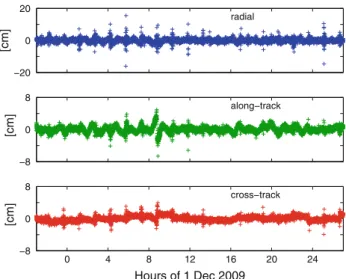
differences between RD and KIN PSO; 31 October 2009 to 10 January 2010 0 4 8 12 16 20 24 −8 0 8 Hours of 1 Dec 2009 [cm] cross−track −20 0 20 [cm] radial −8 0 8 [cm] along−track
Fig. 10 Example for differences in radial, along-track and cross-track
direction between RD and KIN PSO; 1 December 2009
detail inJäggi et al.(2006). KIN orbits (Švehla and Rothacher 2005) have also already successfully been generated with the Bernese GPS Software and have been used for gravity field recovery (see, e.g.,Gerlach et al. 2003;Prange et al. 2010). A band-limited part (±4 epochs) of the full covariance matrix of KIN positions is derived in the course of the KIN orbit determination.
The orbit processing is performed in 30 h batches leading to 6 h overlaps between subsequent days. For the final PSO, however, the orbits are cut to the central 24 h. KIN positions are only provided for the final product if five or more simul-taneous GPS observations are available after data screening. This leads on average to 0.5% of missing KIN positions, implying that the time series of the KIN positions are almost continuous.
The processing time for the PSO is about 3 h on a standard linux PC. Under normal conditions of data availability, the PSO product is delivered 7–10 days after data collection on the satellite.
Nov 1 Nov 10 Nov 20 Dec 1 Dec 10 Dec 20 Jan 1 Jan 10 0.5
1.0 1.5
RMS [cm]
Date in 2009/2010
radial along−track cross−track 3−D
Fig. 11 RMS values (cm) for 5 h overlaps of RD PSO solutions
Figure 9 shows the RMS values for the differences between RD and KIN orbits for the 72-day period. The dif-ferences are evaluated every 10 s (by propagating the RD to the observation epochs of the KIN positions) and epochs with orbit differences larger than 1 m are neglected for this statistic. The number of neglected epochs is 60 for the entire time period. If these epochs would be consecutive, this would correspond to a maximum of 10 min(60 × 10 s) of proba-bly erroneous KIN positions. This is a very small number compared to the length of the considered time period. The mean of the 3D RMS values is 1.82 cm, which confirms an excellent consistency between RD and KIN orbits. No sig-nificant offsets were detected between the two orbit types. Figure 10shows typical orbit differences. Small jumps in the kinematic orbits may occur, e.g., at about 08:30 hours. This may happen after a short data gap leading to a new initialization of all phase ambiguities. Note that the com-parison between RD and KIN orbits does not give infor-mation about the orbit accuracy. The comparison, however, shows that the data quality is very good for the entire data period, because KIN positioning is very sensitive to data problems.
The analysis of the overlaps of subsequent orbits provides another internal quality check. Thanks to the 30 h batch processing, 6 h overlaps may be used. To avoid boundary effects, we only consider the central 5 h (21:30–02:30 hours) of these overlaps. Figure11shows the RMS values for the overlaps of the RD PSO solutions. The mean of the 3D RMS values is 0.55 cm. These results confirm the good consistency and quality of the orbit determination proce-dure.
4.3 Comparison of RSO and PSO
The RSO and the PSO are compared to study the consis-tency of the two products. It has to be emphasized that the low latency solutions are optimized for the quick delivery and not for the best possible result with the involved soft-ware packages. As shown by Montenbruck et al. (2008), the orbits from DEOS are at the same level of accuracy as the AIUB solutions when the same input data are used and the same requirements are met on both sides.
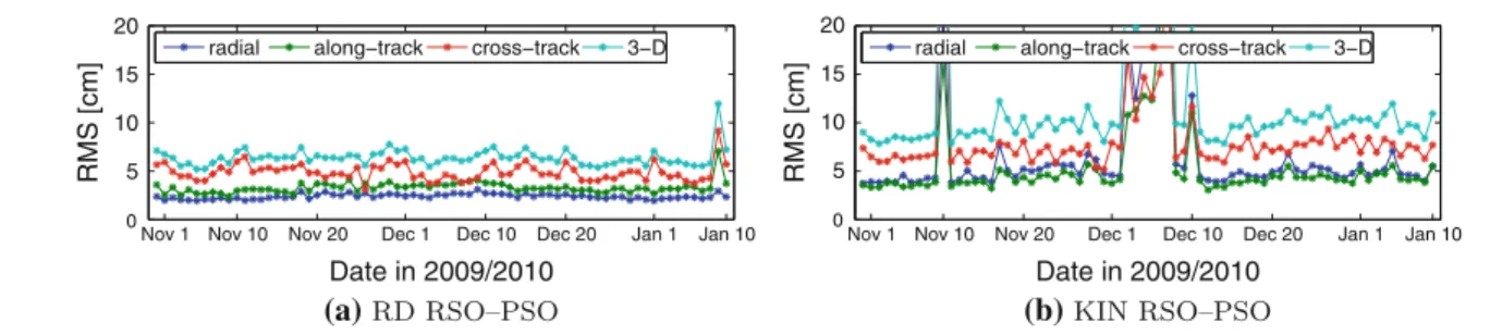
Nov 1 Nov 10 Nov 20 Dec 1 Dec 10 Dec 20 Jan 1 Jan 10 0 5 10 15 20 RMS [cm] Date in 2009/2010
radial along−track cross−track 3−D
Nov 1 Nov 10 Nov 20 Dec 1 Dec 10 Dec 20 Jan 1 Jan 10
0 5 10 15 20 RMS [cm] Date in 2009/2010
radial along−track cross−track 3−D
(a) (b)
Fig. 12 3D RMS values (cm) for differences between RSO and PSO
Figure 12 shows the 3D RMS values for the differ-ences between the RD orbits (Fig12a, mean offset: radial −1.22 cm, along-track 0.39 cm, cross-track 2.43 cm) and between the KIN orbits (Fig12b, 0.24, 0.04, 6.37 cm). The differences between the RD RSO and PSO are below 10 cm and the KIN RSO is, except for some days, at the level of 10 cm with respect to the PSO. Outliers in the comparison between the RD RSO and PSO, e.g., on 9 January 2010, are usually due to data gaps. Due to late data dumps, data gaps in the RSO processing may not be present in the PSO. When a data gap is present in both solutions, the propagation during such a gap may also lead to larger differences. The reasons for the reduced quality of the KIN RSO on some days have been already given in Sect.4.1. The mean cross-track offsets in both comparisons are caused by the cross-track orbit shifts of the PSO due to the empirical PCVs (Bock et al. 2011) used in the PSO but not yet in the RSO processing. The mean radial offset between the RD RSO and the RD PSO of more than 1 cm may be an indication for uncertainties in the antenna offset vectors. The RD RSO is a more dynamic orbit solution than the RD PSO and therefore sensitive to such errors.
Nevertheless, the comparison shows good consistency between the RSO and PSO. The RSO has despite its low latency requirements a very good quality and considering the accuracy of the PSO (see Sect.5) it can be concluded that the RSO meets the accuracy requirement of 0.5 m with a large margin.
5 Validation with SLR measurements
The International Laser Ranging Service (ILRS,Pearlman et al. 2002) provides SLR measurements to the GOCE satel-lite. The SLR tracking of the satellite is challenging due to its low altitude resulting in a high velocity and very short passes over the stations (3–4 min). ESA and AIUB (Jäggi et al. 2010) provide predictions to the ILRS community to support well-distributed and regular tracking by the SLR stations.
The SLR measurements are used for an independent val-idation of the GPS-derived orbits. The importance of this independent validation in the case of GOCE is documented inBock et al.(2011). The significant improvements due to
the use of the empirical PCVs could be demonstrated with the SLR validation.
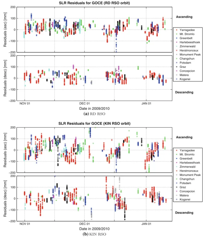
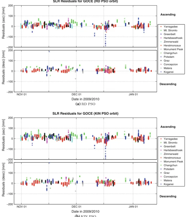
The LRR array consists of several reflectors. Therefore, a nadir-dependent correction of the ranges has to be per-formed. Together with the CoM offsets of the LRR array, these corrections can be found inBigazzi and Frommknecht (2010). The differences between the SLR measurements and the GPS-derived ranges between the satellite and the SLR tracking stations are shown in Figs.13and14for the four different orbit types. SLRF2005 (http://ilrs.gsfc.nasa.gov/ working_groups/awg/SLRF2005.html) coordinates are used for the SLR stations and residuals larger than 20 cm are removed. The residuals are sorted in ascending (dusk) and descending (dawn) passes, because only these passes occur due to the sun-synchronous orbit of the satellite. The sep-aration between ascending and descending passes is made to identify possible problems in one of the two pass types, which was very helpful in the beginning of the mission. The distribution of passes has been very inhomogeneous during the commissioning phase of the mission (not shown here). Before correcting for the PCVs, the cross-track orbit shift (Bock et al. 2011) showed up with different sign in ascend-ing and descendascend-ing passes (Jäggi et al. 2010) depending on the azimuth and elevation of the SLR measurement. Table5 summarizes the statistics of the validation, which no longer shows specific differences between ascending and descend-ing passes. The numbers in Table5confirm that the mission requirements for both orbit products are met. The RSO qual-ity is better than 10 cm, which is far below the requirement of 50 cm. The accuracy of the PSO is at the 2 cm level, though a quite large offset of 0.88 cm is still present in the data. Comparisons of the PSO with more dynamical orbits could be very helpful to find the reason for it.
6 Summary and conclusions
GOCE, the first Earth explorer core mission from ESA, is now in orbit since more than 1 year. The orbit genera-tion based on GPS observagenera-tions from the onboard Lagrange receiver has been established within the GOCE HPF. DEOS and AIUB are delivering the RSO and the PSO, respectively,
Ascending Descending −200 −100 0 100 200 Residuals (asc) [mm]
SLR Residuals for GOCE (RD RSO orbit)
NOV 01 DEC 01 JAN 01
−200 −100 0 100 200 Date in 2009/2010 Residuals (desc) [mm] Yarragadee Mt. Stromlo Greenbelt Hartebeesthoek Zimmerwald Herstmonceux Monument Peak Changchun Potsdam Graz Concepcion Matera Koganei Ascending Descending −200 −100 0 100 200 Residuals (asc) [mm]
SLR Residuals for GOCE (KIN RSO orbit)
NOV 01 DEC 01 JAN 01
−200 −100 0 100 200 Date in 2009/2010 Residuals (desc) [mm] Yarragadee Mt. Stromlo Greenbelt Hartebeesthoek Zimmerwald Herstmonceux Monument Peak Changchun Potsdam Graz Concepcion Matera Koganei (a) (b)
Fig. 13 SLR residuals for RSO
on a routine basis. First orbit results of a 72-day period in 2009 and 2010 were presented here. The almost continuous 1 Hz data availability from the 12-channel space-borne GPS receiver is unique and allows for a time series of KIN posi-tions with only 0.5% of missing epochs.
The RSO and PSO generation procedures were briefly recapitulated and the different characteristics and used
mod-els were summarized. The RSO results show that the low latency (1 day) as well as the accuracy requirements (0.5 m) are easily met. The accuracy was found to be better than 10 cm. The consistency of the RSO and PSO is also at this level. The excellent internal quality of the PSO is underlined by the mean 3D RMS values of the differences between RD and KIN PSO with 1.82 cm and for the overlap
Ascending Descending −200 −100 0 100 200 Residuals (asc) [mm]
SLR Residuals for GOCE (RD PSO orbit)
NOV 01 DEC 01 JAN 01
−200 −100 0 100 200 Date in 2009/2010 Residuals (desc) [mm] Yarragadee Mt. Stromlo Greenbelt Hartebeesthoek Zimmerwald Herstmonceux Monument Peak Changchun Potsdam Graz Concepcion Matera Koganei (a) Ascending Descending −200 −100 0 100 200 Residuals (asc) [mm]
SLR Residuals for GOCE (KIN PSO orbit)
NOV 01 DEC 01 JAN 01
−200 −100 0 100 200 Date in 2009/2010 Residuals (desc) [mm] Yarragadee Mt. Stromlo Greenbelt Hartebeesthoek Zimmerwald Herstmonceux Monument Peak Changchun Potsdam Graz Concepcion Matera Koganei (b)
Fig. 14 SLR residuals for PSO
Table 5 Statistics of SLR validation
Orbit Mean (cm) RMS (cm)
RSO RD 1.29 4.10
RSO KIN 0.53 7.14
PSO RD 0.88 2.05
PSO KIN 0.88 2.23
analysis of the RD orbits with 0.55 cm. The independent SLR validation states an accuracy at the level of 2 cm for the PSO, which corresponds to the mission require-ment.
Acknowledgments The authors acknowledge the European Space Agency for the provision of the GOCE data. Significant parts of the work described in this study were financed through the European Space Agency contract no. 18308/04/NL/MM for the design, development and operation of the GOCE Level 2 data processing system. The con-tributions of CODE are also gratefully acknowledged. CODE is a joint
venture of AIUB, Swiss Federal Office of Topography (swisstopo), Wabern, Switzerland, the German Federal Office of Cartography and Geodesy (BKG), Frankfurt a. Main, Germany, and the Institut für Astro-nomische and Physikalische Geodäsie (IAPG), Technische Universität München, Germany.
References
Altamimi Z, Collilieux X, Legrand J, Garayt B, Boucher C (2007) ITRF2005: a new release of the International Terrestrial Refer-ence Frame based on time series of station positions and Earth Orientation Parameters. J Geophs Res 112(B9):401–419. doi:10. 1029/2007JB004949
Bigazzi A, Frommknecht B (2010) Note on GOCE instruments positioning. Issue 3.1. http://earth.esa.int/download/goce/GOCE- LRR-GPS-positioning-Memo_3.1_[XGCE-GSEG-EOPG-TN-09-0007v3.1].pdf
Bock H (2004) Efficient methods for determining precise orbits of low Earth orbiters using the Global Positioning System. Geodätis-ch-geophysikalische Arbeiten in der Schweiz, Band 65, Schwei-zerische Geodätische Kommission, Institut für Geodäsie und Photogrammetrie, Eidg. Technische Hochschule Zürich, Zürich Bock H, Jäggi A, Švehla D, Beutler G, Hugentobler U, Visser
P (2007) Precise orbit determination for the GOCE satellite using GPS. Adv Space Res 39(10): 1638–1647. doi:10.1016/j.asr.2007. 02.053
Bock H, Dach R, Jäggi A, Beutler G (2009) High-rate GPS clock cor-rections from CODE: support of 1 Hz applications. J Geod 83(11): 1083–1094. doi:10.1007/s00190-009-0326-1
Bock H, Jäggi A, Meyer U, Dach R, Beutler G (2011) Impact of GPS antenna phase center variations on precise orbits of the GOCE satellite. Adv Space Res. 47(11):1885–1893 doi:10.1016/j.asr. 2011.01.017
Dach R (2009) Code analysis center down. IGS Mail No. 6033. IGS Central Bureau Information System
Dach R, Hugentobler U, Fridez P, Meindl M (eds) (2007) Bernese GPS Software Version 5.0. Astronomical Institute, University of Bern, Bern, Switzerland.http://www.bernese.unibe.ch/docs/DOCU50. pdf, user manual
Dach R, Brockmann E, Schaer S, Beutler G, Meindl M, Prange L, Bock H, Jäggi A, Ostini L (2009) GNSS processing at CODE: status report. J Geod 83(3–4): 353–365. doi: 10.1007/s00190-008-0281-2
Dow JM, Neilan RE, Rizos C (2009) The International GNSS Service in a changing landscape of Global Navigation Satellite Systems. J Geod 83(3–4): 191–198. doi:10.1007/s00190-008-0300-3
Drinkwater M, Haagmans R, Muzi D, Popescu A, Floberghagen R, Kern M, Fehringer M (2006) The GOCE gravity mission: ESA’s first core explorer. In: Proceedings of the 3rd GOCE User Workshop, 6–8 Nov 2006, Frascati, Italy, ESA SP-627, pp 1–7
ESA (2010a) GOCE Level 2 Product Data Handbook.http://earth. esa.int/pub/ESA_DOC/GOCE/GO-MA-HPF-GS-0110_4.2-ProductDataHandbook.pdf
ESA (2010b) GOCE Standards. http://earth.esa.int/pub/ESA_DOC/ GOCE/GOCE_Standards_3.2.pdf
Förste C, Flechtner F, Schmidt R, Stubenvoll R, Rothacher M, Kusche J, Neumayer H, Biancale R, Lemoine JM, Barthelmes F, Bruinsma S, König R, Meyer U (2008) EIGEN-GL05C— a new global combined high-resolution GRACE-based gravity field model of the GFZ-GRGS cooperation. Geophys Res Abstr 10:EGU2008-A-03426
Gerlach C, Földváry L, Švehla D, Gruber T, Wermuth M, Sneeuw N, Frommknecht B, Oberndorfer H, Peters T, Rothacher M, Rummel R, Steigenberger P (2003) A CHAMP-only gravity field model
from kinematic orbits using the energy integral. Geophys Res Lett 30(20):2037. doi:10.1029/2003GL018025
Gurtner W (1994) RINEX: the receiver-independent exchange format. GPS World 5(7):48–52. Format specifications available atftp:// igscb.jpl.nasa.gov/igscb/data/format/rinex2.txt
Intelisano A, Mazzini L, Notarantonio A, Landenna S, Zin A, Scaciga L, Marradi L (2008) Recent flight experiences of TAS-I on-board nav-igation equipments. In: Proceedings of the 4th ESA workshop on satellite navigation user equipment technologies, NAVITEC’2008, 10–12 Dec 2008, Noordwijk, The Netherlands
Jäggi A, Hugentobler U, Beutler G (2006) Pseudo-stochastic orbit mod-eling techniques for low-Earth orbiters. J Geod 80(1): 47–60. doi:10.1007/s00190-006-0029-9
Jäggi A, Hugentobler U, Bock H, Beutler G (2007) Precise orbit deter-mination for GRACE using undifferenced or doubly differenced GPS data. Adv Space Res 39(10): 1612–1619. doi:10.1016/j.asr. 2007.03.012
Jäggi A, Dach R, Montenbruck O, Hugentobler U, Bock H, Beutler G (2009) Phase center modeling for LEO GPS receiver antennas and its impact on precise orbit determination. J Geod 83(12): 1145–1162. doi:10.1007/s00190-009-0333-2
Jäggi A, Bock H, Floberghagen R (2010) GOCE orbit predictions for SLR tracking. GPS Solut 15(2): 129–137. doi: 10.1007/s10291-010-0176-6
Jäggi A, Bock H, Prange L, Meyer U, Beutler G (2011) GPS-only grav-ity field recovery using GOCE, CHAMP, or GRACE. Adv Space Res 47(6): 1020–1028. doi:10.1016/j.asr.2010.11.008
Koop R, Gruber T, Rummel R (2006) The status of the GOCE high-level processing facility. In: Proceedings of the 3rd GOCE User Work-shop, 6–8 Nov 2006, Frascati, Italy, ESA SP-627, pp 199–205 Lyard F, Lefevre F, Letellier T, Francis O (2006) Modelling the global
ocean tides: insights from FES2004. Ocean Dyn 56: 394–415. doi:10.1007/s10236-006-0086-x
McCarthy DD, Petit G (2004) IERS conventions 2003. IERS technical note no. 32. Bundesamt für Kartographie und Geodäsie, Frankfurt am Main, Germany
Montenbruck O, van Helleputte T, Kroes R, Gill E (2005) Reduced dynamic orbit determination using GPS code and carrier measure-ments. Aerosp Sci Technol 9(3): 261–271. doi:10.1016/j.ast.2005. 01.003
Montenbruck O, Andres Y, Bock H, van Helleputte T, van den IJs-sel J, LoiIJs-selet M, Marquardt C, Silvestrin P, Visser P, Yoon Y (2008) Tracking and orbit determination performance of the GRAS instrument on MetOp-A. GPS Solut 12(4): 289–299. doi:10.1007/s10291-008-0091-2
Niell AE (1996) Global mapping functions for the atmosphere delay of radio wavelengths. J Geophys Res 101(B2):3227–3246 Pail R, Bruinsma S, Migliaccio F, Förste C, Goiginger H, Schuh WD,
Höck E, Regguzoni M, Brockmann JM, Abrikosov O, Veicherts M, Fecher T, Mayrhofer R, Krasbutter I, Sansò F (2011) First GOCE gravity field models derived by three different approaches. J Geod. doi:10.1007/s00190-011-0467-x
Pavlis D, Poulouse S, McCarthy J (2006) GEODYN Operations Man-ual. Contractor report, SGT Inc., Greenbelt, MD
Pearlman M, Degnan J, Bosworth J (2002) The International Laser Ranging Service. Adv Space Res 30(2): 135–143. doi:10.1016/ S0273-1177(02)00277-6
Prange L, Jäggi A, Dach R, Bock H, Beutler G, Mervart L (2010) AIUB-CHAMP02S: the influence of GNSS model changes for grav-ity field recovery using spaceborne GPS. Adv Space Res 45(2): 215–224. doi:10.1016/j.asr.2009.09.020
Reigber C, Lühr H, Schwintzer P (2002) CHAMP mission status. Adv Space Res 30(2): 129–134. doi:10.1016/S0273-1177(02)00276-4
Rothacher M, Schmid R (2010) ANTEX: the antenna exchange format, version 1.4. IGS Central Bureau Information System,ftp://ftp.igs. org/pub/station/general/antex14.txt
Rummel R, Balmino G, Johannessen J, Visser P, Woodworth P (2002) Dedicated gravity field missions—principles and aims. J Geodyn 33: 3–20. doi:10.1016/S0264-3707(01)00050-3
Schmid R, Steigenberger P, Gendt G, Ge M, Rothacher M (2007) Gen-eration of a consistent absolute phase center correction model for GPS receiver and satellite antennas. J Geod 81(12): 781–798. doi:10.1007/s00190-007-0148-y
Standish EM (1998) JPL planetary and lunar ephemerides, DE405/LE405. JPL IOM 312.F-98-048.
Švehla D, Rothacher M (2005) Kinematic precise orbit determination for gravity field determination. In: Sansò F (ed) A window on the future of geodesy, vol 128. Springer, Berlin, pp 181–188. doi:10. 1007/3-540-27432-4_32
Tapley B, Bettadpur S, Watkins M, Reigber C (2004) The gravity recov-ery and climate experiment: mission overview and early results. Geophys Res Lett 31(9):L09607. doi:10.1029/2004GL019920
van den IJssel J, Visser P, Rodriguez EP (2003) CHAMP precise orbit determination using GPS data. Adv Space Res 31(8):1889–1895. doi:10.1016/S0273-1177(03)00161-3
van Helleputte T (2004) User manual for the GHOST orbit determina-tion software. Deutsches Zentrum für Luft- und Raumfahrt, Ober-pfaffenhofen, fDS-SUM-3110
Visser P, van den IJssel J, van Helleputte T, Bock H, Jäggi A, Beu-tler G, Hugentobler U, Švehla D (2006) Rapid and precise orbit determination for the GOCE satellite. In: Proceedings of the 3rd GOCE user workshop, 6–8 Nov 2006, Frascati, Italy, ESA SP-627, pp 235–239
Visser P, van den IJssel J, van Helleputte T, Bock H, Jäggi A, Beutler G, Švehla D, Hugentobler U, Heinze M (2009) Orbit determination for the GOCE satellite. Adv Space Res 43(5): 760–768. doi:10. 1016/j.asr.2008.09.016
Zumberge JF, Heflin MB, Jefferson DC, Watkins MM, Webb FH (1997) Precise point positioning for the efficient and robust analysis of GPS data from large networks. J Geophys Res 102(B3): 5005–5017. doi:10.1029/96JB03860