Received: 4 April 2003 Revised: 30 June 2003 Accepted: 1 August 2003
Published online: 31 October 2003 © Springer-Verlag 2003
Abstract X-rays, the key ingredient of radiology, are still primarily pro-duced with the mechanism discov-ered by Röntgen over one century ago. A different approach, however, is becoming increasingly important: the use of synchrotron sources based on fast-moving electrons and on their relativistic properties. We discuss the elements of this new strategy, its practical implementa-tion, and some new types of syn-chrotron sources under development. The present and potential impact on radiology of different classes of synchrotron sources is briefly and realistically analyzed.
Keywords Synchrotron · Storage ring · Undulator · Wiggler · Bending magnet · Free-electron laser · Self-amplified spontaneous emission G. Margaritondo
R. Meuli
Synchrotron radiation in radiology:
novel X-ray sources
Introduction
X-rays are the basic tool of radiologists: the performances of X-ray sources directly affect those of radiological tech-niques. The overwhelming majority of X-ray medical ex-aminations still use sources based on the emission mecha-nism accidentally discovered [1] in 1895 by Wilhelm Conrad Röntgen.
The classic Röntgen mechanism [1] is based on excit-ing the electrons in a material to suitably high energies by bombarding the material with a high-energy electron beam. This mechanism, although very widely used, has inherent problems that limit the source performances. For example, X-rays are emitted in all directions and therefore most of them are wasted: only those reaching the imaged object are used for a radiograph. The situa-tion is similar to that of a lamp compared with a torch-light: the torchlight may emit less light than the lamp, but it is more effective and less wasteful when we want to illuminate a specific object. A torchlight corrects the
lamp problems—specifically, lack of collimation—by using a focusing mirror. No such mirrors exist for X-rays; therefore, they cannot be used to transform a standard source into the equivalent of a torchlight.
For many radiology applications, the lack of collima-tion of convencollima-tional X-ray sources based on the Röntgen mechanism does not constitute a problem. In fact, con-ventional sources provide the large field of view which is required by many of such applications and in particu-lar for all routine techniques; however, a non-conven-tional source emitting a narrow beam in a well-defined direction is required for several novel radiology tech-niques.
What prevents us from employing other types of sources besides those based on the Röntgen mechanism as we do, for example, for visible light? Unfortunately, sources such as lasers, incandescent lamps, antennas (like in radio emitters), or fluorescence lamps, perfectly suitable for other types of electromagnetic radiation, do not work for X-rays. Building X-ray lasers is an exceed-G. Margaritondo (
✉
)Faculté des sciences de base, Ecole Polytechnique Fédérale de Lausanne (EPFL), 1015 Lausanne, Switzerland e-mail: [email protected] Tel.: +41-21-6934471 Fax: +41-21-6934465 R. Meuli Service de Radiodiagnostic
et Radiologie Interventionnelle, CHUV, 1011 Lausanne, Switzerland
ingly difficult enterprise. In incandescent lamps, the fila-ment temperature determines the emitted wavelengths, and the emission of X-rays would require temperatures well above the melting point of all materials. Antennas cannot be used since electrons cannot be forced to oscil-late along them with high enough frequencies to emit X-rays.
In fluorescent lamps, electrons in a gas are brought to an excited state by an electric discharge. While falling back into their unexcited state, they emit photons of en-ergy equal to the electron enen-ergy jump. For X-rays, the photon energy and the corresponding energy jump would have to be much larger than for visible light, and elec-trons cannot be excited to a sufficiently high energy by a gas discharge. There is, however, a way to overcome these limitations and obtain intense and narrow beams of X-rays: the use of synchrotron sources.
This article explains the mechanism of such sources in very simple terms, discusses its practical implementa-tion, and presents some foreseeable future developments. It also reviews how the advanced characteristics of syn-chrotron sources are exploited in novel radiology tech-niques.
Synchrotron radiation sources:
the moving antenna model
To understand how a synchrotron source works, the idea of emitting X-rays with an antenna, like radio waves, must be reviewed. This notion is normally quickly dis-missed because of the excessively high oscillation fre-quencies. There exists, however, a way to bypass this ob-stacle.
It is well known that the frequency (and wavelength) emitted by a moving source of radiation is shifted when seen by a fixed observer. This is the so-called Doppler effect, which also occurs for sound waves such as for Doppler ultrasound (Fig. 1a): the whistle of a train has a higher (or lower) pitch when the train moves towards (or away from) the observer.
Could we then use a fast-moving antenna to produce X-rays in the laboratory frame (as shown in Fig. 1b)? The question is: How fast should the antenna travel? Ele-mentary optics [2] tells us that if a source moving to-wards a fixed observer with speed v emits a wavelength λ in its own frame, then the fixed observer detects a Doppler-shifted wavelength:
(1) where c is the speed of the waves, which in the case of rays electromagnetic waves, such as X-rays, is the speed of light. This implies that:
(2)
A typical wavelength emitted by a radio wave antenna is λ≈0.01–0.1 m, whereas a typical X-ray wavelength is, for example,λ’≈1 Å=0.0000000001 m. This means that λ’/λis extremely small; thus, Eq. (2) predicts v/c≈1, and our moving antenna should run with a speed very close to the speed of light (c).
Is this impossible? For many decades, high-energy physicists have used particle accelerators in which elec-trons and other particles move at speeds very close to c; therefore, the possibility does exist. Specifically, in a storage ring electrons are injected and then circulate at very high speed for hours or days along a closed trajec-Fig. 1a–c The Doppler effect, a key ingredient of synchrotron sources. a In the case of acoustic waves, the source motion (speed equals v) changes the wavelength and the frequency, and thus the pitch of the sound detected by a fixed observer. b Similarly, a fixed observer detects a Doppler-shifted wavelength when electro-magnetic waves are emitted by a moving antenna. c An electron circulating at high speed in a particle accelerator and undulating in the transverse direction is equivalent to a fast-moving antenna. The Doppler shift enables it to produce X-ray wavelengths in the fixed frame of the laboratory: this is the “secret” of synchrotron sources
tory. Their motion is controlled by a sophisticated system of magnets. If we could induce these electrons to oscillate in the transverse direction (Fig. 1c), then they would behave like mini-antennas moving at nearly the speed of light—and produce X-rays in the laboratory frame. This is, fundamentally, the strategy of synchro-tron radiation sources [2, 3].
Synchrotron source properties
Before discussing this approach further , we note that us-ing an electron accelerator is neither simple nor inexpen-sive. We must therefore find very good reasons before accepting the additional complications, infrastructure, and cost. An excellent reason does indeed exist: the ac-celerator-based strategy leads to sources with small size, small angular divergence, and very high power—sources that are required for several novel radiology techniques but cannot be provided by the standard Röntgen mecha-nism.
Antenna-like fast-moving electrons emit an X-ray beam with small cross section and very limited angular divergence, similar to a torchlight. The X-ray beam cross section is determined by the source size [2, 3]. In turn, the source size is determined by the cross section of the beam of electrons circulating in the accelerator, which can be extremely small. The accelerator technology is now so sophisticated that the electron trajectories, and therefore the electron-beam cross section, can be con-trolled with an accuracy better than 1/1000 of a millime-ter over a circumference of several hundred memillime-ters.
Why is the angular divergence of a synchrotron source very small? This is again due to the motion of the electron source. In imagining the sound wave emitted by a car horn (see Fig. 2a), if the car is not moving, the emitted pattern is approximately spherical; otherwise, the car velocity is combined with that of the sound— which is “projected ahead” in the direction of the car motion. This concentrates most of the sound intensity within a limited angular range.
A similar effect occurs for the X-rays emitted by a moving electron. The angular concentration becomes very extreme when the source moves at “relativistic” speeds close to c. Quantitatively speaking, the source motion confines (Fig. 2b) the emitted X-rays into an an-gular range ≈1/γ, where theγ-factor is defined as:
(3)
Therefore,γ increases (and 1/γ decreases) as the source speed v increases. In a synchrotron source, the electron speed corresponds to typical γ-factor values between 1000 and 16000, so that the 1/γ angular spread is ex-tremely small, ranging from 1/1000 to 1/16000 radians.
It is noteworthy that theγ-factor also characterizes the energy of the circulating electrons in the accelerator. In fact,γequals the (relativistic) energy of the electrons di-vided by their “rest energy,” Einstein’s famous moc2. The above-mentioned range of γ-values corresponds to accelerator energies between 500 and 8000 megaelec-tronvolt (MeV).
In addition to its excellent geometric characteristics, the synchrotron emission of the antenna-like fast-moving electrons is also very powerful [2, 3]. In a conventional X-ray source, the emitted power cannot be increased be-yond certain limits. In fact, the electron beam injects a lot of heat power into the anode; only a minimal part of it is converted into X-rays and the anode must absorb the rest. Beyond a certain power level, the anode is damaged or destroyed.
In an accelerator, the electrons act as free particles rather than as components of a solid anode. The power conversion into X-rays is quite direct and the achievable power levels are much higher than in a conventional source.
Undulators, wigglers, and bending magnets
Having justified the use of electron accelerators as X-ray sources, we now discuss the practical problem of trans-forming circulating electrons in an accelerator into mini-antennas. We have already seen that the electron must be forced to undulate in the transverse direction with re-spect to its unperturbed trajectory (Fig. 1c). Seen from the point of view of a fixed observer along the forward Fig. 2 The source motion produces angular collimation in the emitted waves. a The acoustic wave emitted by a car horn corre-sponds to an approximately spherical pattern when the car does not move. If the car is in motion, its speed combines with that of the wave, projecting ahead the wave and therefore collimating it. b A similar effect exists for synchrotron radiation and is enhanced by relativistic effects since the source speed is close to the speed of light
direction, the electron looks indeed like an electric charge oscillating in a straight line—similar to the charges in a radio antenna.
How can the transverse undulation be induced? The solution is simple: a periodic array of magnets, called “undulator,” placed along the straight trajectory acts on the electrons with a Lorentz force, causing an equally periodic undulation. Figure 3a illustrates this strategy which is adopted by most synchrotron sources.
A detailed analysis of the undulations (Fig. 3b) re-veals another important effect of the relativistic speed of the electrons. From the point of view of the electrons, the magnet array looks like a periodic electromagnetic field (with period L) moving towards them at a speed ≈c,
i.e., like an electromagnetic wave. Subject to the action of this “primary” wave, the electrons emit in turn “sec-ondary” electromagnetic waves with the same wave-length. These secondary waves are what we call syn-chrotron radiation.
It is noteworthy, however, that the period L of the undulator is much longer than the typical wavelengths of rays: Why, then, is synchrotron radiation made of X-rays? The answer is that when “seen” by the moving electrons the period L is shortened by an amazing rela-tivistic effect called “Lorentz contraction.”
Suppose that the length of a rod is measured first by a fixed observer and then by an observer moving in the direction of the rod. The measured length is shorter in the second case than in the first. Similarly, the moving electrons “see” a shorter undulator and therefore shorter undulator periods. Since the electron speed is close to the speed of light, relativity predicts a contracted period ≈L/γ. This is also, in first approximation, the wavelength
of the radiation emitted by the electrons when “seen” from their point of view.
When observed from the laboratory, this wavelength is shifted by the Doppler effect, in agreement with Eq. (1). For v≈c, the square-root factor in Eq. (1) is close
to 1/(2γ), so that the emitted wavelength seen in the lab-oratory approximately equals L/γ multiplied by 1/(2γ), i.e.:
(4) This simple result enables us to understand quite a lot about synchrotron sources. We cannot build magnet arrays with periods as short as the wavelengths of X-rays; however, by using fast-moving electrons we exploit relativity to practically shorten the size (period) of magnet arrays. The scaling factor 2γ2 of Eq. (4) reflects two combined effects: the Lorentz contrac-tion and the Doppler shift. Considering the above-mentioned values ofγ, we can start from a period L of a few centimeters and convert it into X-ray wavelengths from hundreds of angstroms to a fraction of an ang-strom.
The arguments used to understand undulators can be extended to other types of devices used to emit synchro-tron radiation. In practice, two other magnet devices be-sides the undulators are used as synchrotron sources, in particular for radiology: bending magnets and wigglers [2, 3].
Bending magnets are always present in storage rings. They are used to deflect the velocity of the electrons keeping them in a closed trajectory (which is in fact a combination of straight and curved sections), as shown in Fig. 1c.
A wiggler is a magnet array similar to an undulator except that its magnet field is stronger and the transverse undulations of the electrons are more pronounced.
The basic difference between undulators, wigglers, and bending magnets is the emitted spectrum of wave-lengths (see Fig. 4). An undulator emits a narrow band of wavelengths centered at the valueλ’ given by Eq. (4). In addition, it also emits narrow bands centered at the “har-monics”λ’/3,λ’/5, etc. (and, off-axis,λ’/2,λ’/4, etc.) [2, 3]. A wiggler and a bending magnet emit instead a very broad band of wavelengths. The wiggler is essentially equivalent to a sequence of bending magnets and there-fore is a more powerful source than a single bending magnet.
Fig. 3a, b How can we force fast-moving electrons in an acceler-ator to undulate in the transverse direction and to emit X-rays? a A periodic magnet array (period L) acts on the electrons causing the undulation. b The fast-moving electrons “see” the period L shortened to L/γby the relativistic “Lorentz contraction”. The un-dulating electrons emit electromagnetic waves whose wavelength equals the contracted period L/γ. The Doppler shift further short-ens the wavelength when it is observed in the fixed frame of the laboratory
Some important properties of synchrotron sources
Synchrotron sources are excellent emitters of X-rays from many different points of view. We have already learned about high emitted power, outstanding geometric characteristics, and useful wavelength spectrum. We now briefly discuss other important aspects that also make synchrotron sources powerful and flexible [2, 3].Brightness
The quality of a radiation source can be evaluated con-sidering the total emission per unit time, i.e., the emitted power. This is what we do when we buy a lamp for our home: we look at the electric power used by the lamp since the emitted power (light) is a given fraction of the used power.
Quite often, however, the emitted power cannot suffi-ciently characterize the source quality. In considering a torchlight vs a lamp, the torchlight is much better when we concentrate the light into a specific area. How can we quantitatively express this superiority?
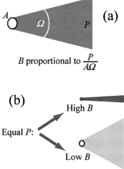
The answer is provided by the quantity called “bright-ness” (or brilliance), B [2, 3]. This is the combination of
three factors: the total emitted power P; the emitting source area A; and the angular divergenceΩof the emis-sion (see Fig. 5). Without worrying about details we can define B as approximately:
(5) We can thus see that the brightness increases if (a) the emitted power increases, and/or (b) the source size becomes smaller, and/or (c) the angular divergence be-comes narrower. For example, the brightness of a torch-light is higher than that of a lamp with equal emitted pow-er and size because the angular divpow-ergenceΩis smaller.
The brightness is very often the parameter of choice to describe the quality of synchrotron sources. Figure 6 shows the spectacular increase in the brightness of X-ray sources starting from the advent of synchrotrons in the 1960s.
The improvement of X-ray sources illustrated by Fig. 6 is virtually unparalleled in science and technology. It has been said that if a car had been improved as much as a computer, it would now cost less than 1 USD (or 1 Euro). On the other hand, if the size of computers had been improved as much as the brightness of synchrotron sources, it would now be 10,000 times smaller than a single atom!
Polarization
Polarization is an important directional property of waves. As it is well known, an electromagnetic wave Fig. 4 Approximate overall picture of the similarities and
differ-ences in the spectrum of wavelengths emitted by undulators, wig-glers, and bending magnets. Top curve: the undulator emission has a strong peak at the wavelengthλ’ specified by Eq. (4), with a nar-row bandwidth. This strong peak is accompanied by weaker har-monics atλ’/2,λ’/3,λ’/4, etc. Bottom curves: both wigglers and bending magnets emit broad-bandwidth spectra
Fig. 5 a The definition of brightness (or brilliance) B of a source. The factors are the emitted power P, the source size A, and the an-gular divergence Ω of the emission. b For equal emitted power and source size, a small and collimated source has higher B than a larger and less-collimated one
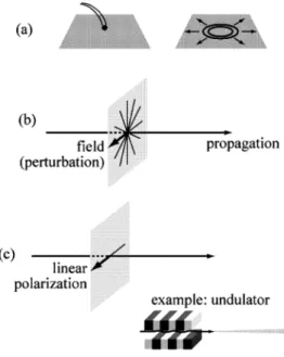
corresponds to the propagation of a perturbation of the electromagnetic field, initially created at the source. The wave electromagnetic field includes two components: an electric field and a magnetic field. Both fields are in transverse directions, i.e., in directions perpendicular to the propagation of the wave.
In some particular cases, the transverse field direc-tions are fixed rather than variable (see Fig. 7), and the corresponding wave is said to be “linearly polarized.” Synchrotron radiation is always polarized. For example, the X-rays produced by an undulator are linearly polar-ized with the wave electric field in the direction of the electron undulations, which normally is horizontal.
Time structure
The radiation emitted by a synchrotron source is not con-tinuous as a function of time but consists of a series of short pulses. The reason is that radiation can be emitted only when electrons are present at the source point, e.g., when they pass through an undulator. The electrons cir-culating around a storage ring are grouped together in bunches; therefore, the emitted radiation consists of pulses whose short duration corresponds to the passage of a bunch.
Between the passage of two adjacent bunches there is no radiation. The resulting time structure (Fig. 8) with short pulses separated by longer “dark” periods is ex-ploited in several time-dependent applications [2, 3]. Fig. 6 The historical increase in the brightness of X-ray sources, from Röntgen’s discovery to the very rapid increase after the ad-vent of synchrotron radiation in the late 1960s
Fig. 7a–c A simple introduction to the notion of polarization. a A “wave” is a perturbation that, initially produced at the source, then propagates away from it, e.g., after a thrown stone perturbs a wa-ter surface the perturbation propagates through wawa-ter waves. b An electromagnetic wave propagates a perturbation of the electromag-netic field, including a magelectromag-netic field and an electric field. The wave-fields directions are both transverse with respect to the wave propagation, but they are not fixed: in the case shown here, the wave electric field can be found in any of the transverse direc-tions. c When the wave is “linearly polarized,” the electric field (and the magnetic field) are in fixed directions. An undulator, for example, emits linearly polarized radiation
Fig. 8 The bunching of the electrons circulating around the stor-age ring and the passstor-age of bunches through the source points (i.e., bending magnets) produces the characteristic time structure of synchrotron radiation, with short pulses separated by longer “dark” intervals
Coherence
Coherence is the special characteristic of waves that en-ables them to produce visible phenomena related to their wave nature. In order to clarify this concept, we can compare the simple illumination of a flat surface by a beam of light and the sequence of bright and dark “inter-ference fringes” produced on the surface when the beam passes through two narrow slits. The illumination is not strictly related to the wave nature of the phenomenon, whereas interference occurs only for waves. Wave-like phenomena include interference and diffraction.
Such phenomena are rarely seen since ordinary sourc-es of light do not posssourc-ess “coherence.” On the contrary, a laser is highly coherent and produces visible phenomena of this kind. The reason [2, 3] is that the emitting surface of a laser is very small, its emission is highly collimated, and the emitted wavelength bandwidth is narrow.
We can thus understand that a conventional X-ray source for radiology is certainly not coherent: its emit-ting surface is very large, the emission is not collimated, and it occurs over a very broad wavelength bandwidth. Synchrotron sources, instead, can be highly coherent. We have seen, in fact, that undulators are small in size, colli-mated and with a very narrow wavelength bandwidth.
No coherent X-ray source was available until the ad-vent of synchrotrons. The adad-vent of coherent X-rays is in that sense equivalent to a revolution for X-ray tech-niques. This applies, in particular, to radiological imag-ing by coherence-based contrast. [3, 4, 5, 6, 7, 8, 9, 10, 11, 12, 13, 14, 15, 16].
Why is coherence so difficult to obtain for X-rays, whereas coherent sources are much easier to obtain for visible light? The key is the wavelength: the specific quantitative conditions for coherence [3] depend on the wavelength and are much more difficult to fulfill for short-wavelength X-rays than for visible light. That is why only now, more than one century after Röntgen’s discovery [1], coherence can impacts radiology and other X-ray applications.
The synchrotron facility
A synchrotron facility includes not only a synchrotron source but also many other components, as required for the practical use of synchrotron radiation [2, 3]. The spe-cific components of each facility depend on its spespe-cific applications.
The synchrotron source—the storage ring—includes bending magnets, wigglers, and undulators that consti-tute individual source points. For each source point there is a beamline (Fig. 9) departing from the ring in the tan-gential direction. Each beamline collects the X-ray beam, improves its characteristics, and delivers it to the apparatus required for a specific application.
The X-ray beam improvements along a beamline typi-cally include (a) filtering by a “monochromator” to nar-row the wavelength band ∆λ, and (b) focusing to reduce the transverse beam size. These improvements require adequate optical devices. Such devices cannot function in transmission since solid materials absorb X-rays. For example, focusing is typically achieved with mirrors rather than with standard lenses that do not exist for X-rays. Because of this and other complications, the op-tical devices of an X-ray beamline are technically very sophisticated and quite expensive.
A single storage ring can provide X-rays for many beamlines and therefore support many (in some cases more than 100) applications in parallel. This is a crucial factor in decreasing the costs of each application.
The storage ring and the beamlines are complemented by specialized equipment required for specific applica-tions. This is a delicate issue in the case of medical ap-plications, including radiological examinations. The spe-cialized infrastructure in that case cannot be limited to the X-ray equipment. It is difficult, in fact, to bring pa-tients into a scientific research environment, such as a synchrotron facility, without risking psychological and practical problems. The correct handling of patients re-quires transforming the corresponding part of the syn-chrotron facility and creating a hospital-like environ-ment.
How can synchrotron sources be optimized
for radiology?
The strategy of producing X-rays by using accelerated electrons can be implemented with other approaches be-Fig. 9 In a synchrotron facility, at each source point there is a tan-gentially departing beamline that improves the X-ray beam and delivers it to an experimental chamber for a specific application. Several optical components are used to improve the beam, such as, for example, focusing mirrors (FM) and a monochromator (M) to reduce the wavelength bandwidth
sides those based on storage rings [3]. Storage rings are getting close to their natural brightness limits. Some im-provements are still possible, but they would require large-diameter and therefore expensive machines; many laboratories throughout the world are exploring alternate approaches. The sources based on “LINACS” (LINear ACcelerators), such as the “energy recovery LINACs,” and the X-ray free-electron lasers [2, 3] are also note-worthy.
There is another class of synchrotron sources that is potentially very important for medical radiology: the “in-verse Compton scattering” sources [3, 16]. Their strategy is to send a visible or infrared laser beam to collide head-on with an electrhead-on beam in an accelerator (see Fig. 10). As the laser beam is backscattered by the electron beam, its wavelength is dramatically shortened moving to the X-ray domain.
This wavelength-shortening mechanism can be easily understood. Seen from the point of view of the fast-mov-ing electrons, the laser beam wavelength is shortened by the Doppler effect of Eq. (1). We have already seen that for v≈c the square-root factor in Eq. (1) is close to 1/(2γ),
so that the wavelength appears shortened by the same factor. The laser beam acts on the electrons forcing them to oscillate and emit electromagnetic radiation, which forms the backscattered beam. Seen from the laboratory, this radiation is emitted by a moving source (the elec-trons) and therefore again subject to the Doppler shift which shortens the wavelength by another factor ≈1/(2γ). Overall, therefore, the backscattered wavelengthλ’ is shortened with respect to the laser wavelength λ by a factor [1/(2γ)]×[1/(2γ)]=1/(2γ)2:
(6) Assuming, for example, that the laser wavelength λ is ≈5000 Å, and that we want to produce X-rays with λ’≈0.5 Å, the correspondingγ-factor in Eq. (6) would be ≈50. This can be achieved with a small and relatively in-expensive electron accelerator.
Compton-backscattering sources can in fact be de-signed as compact devices with the size of 1–3 m [3, 16]. For medical applications, they would thus not be affect-ed by the cost and size problems affecting storage rings. On the other hand, Compton-backscattering sources can-not achieve the brightness and coherence levels of stor-age rings, although this is not a serious limitation for medical radiology.
The invention of a superior source of X-rays consti-tutes, at least potentially, an important development for radiology; however, several conditions must be fulfilled to transform a potential interest into a real impact. We must thus ask: Which one(s) of the present and future types of synchrotron sources can be really useful for medical radiology?
All types of synchrotron sources provide wavelength tunability which is certainly important for medical radi-ology [16]. Very high brightness, however, is required only for specialized applications. Coherence is used by interesting new techniques such as “phase-contrast radi-ology” [5, 6, 7, 8, 9, 10, 11, 12, 13, 14, 15, 16]; however, the coherence level required for such techniques is quite limited.
We can therefore conclude that the use in medical ra-diology will be restricted to “standard” storage rings and, possibly, to inverse Compton-scattering machines. One good point about the possible use of storage rings in medical radiology is that they have become very reliable and quite easy to operate; however, a realistic analysis must also consider other practical issues such as the size of the source, the infrastructure, the immobility, and the construction and operating costs. A storage ring suitable for radiology cannot be reduced in size without jeopar-dizing its reliability. The typical size cannot be recon-ciled with a standard radiological cabinet. We should thus think in terms of regional facilities dedicated to syn-chrotron-radiation radiology and equipped with a com-plete clinical infrastructure. The corresponding costs, the Fig. 10a–c Scheme of a Compton-backscattering source [9]. a A
laser beam is sent head-on against a bunch of electrons after they are brought to high speed by an accelerator. The laser beam is backscattered and its wavelength changes from the visible or in-frared domain to X-rays. b The first factor in the wavelength change is the Doppler effect, present when the laser beam is “seen” by the moving electrons. c The second factor is the Dopp-ler effect caused by the motion of the sources of backscattered light, the electrons, with respect to the laboratory
logistics, and the inconvenience of using a centralized facility and the positive aspects, such as the improve-ment of the quality of the diagnosis achieved by syn-chrotron-based examination, must form the subject mat-ter of a detailed cost-benefit analysis.
The implementation of a reliable, compact, and low-cost Compton-backscattering source may be the key-stone for the use of synchrotron radiation in medical ra-diology [9]. Such a source may in fact be attractive even for conventional medical radiology as a replacement of standard X-ray sources. The development of this class of
devices is still underway [16] and it is too early to make reliable predictions; however, this could potentially be one of the greatest revolutions in the history of radiology since Röntgen’s discovery [1].
Acknowledgements Acknowledgements. Our work in synchro-tron radiology is performed at the PLS facility in Korea, at SRRC-Taiwan, at the Argonne APS, and at Elettra in Trieste. Our re-search programs in this domain are supported by the “Fonds Na-tional Suisse de la Recherche Scientifique” and by the “Ecole Polytechnique Fedérale de Lausanne”.
References
1. Röntgen WC (1895) Ueber eine neue Art von Strahlen. Vorlaeufige Mitteilung Sitzungsber. Physic.-med. Ges., Wuertzburg, pp 132–141 2. Margaritondo G (2003) Elements
of synchrotron radiation for chemistry, biology and medical research. Oxford University Press, New York
3. Margaritondo G (1988) Introduction to synchrotron radiation. Oxford Univer-sity Press, New York
4. Hwu Y, Tsai Wen-Li, Groso A, Margaritondo G, Je Jung Ho (2002) Coherence-enhanced synchrotron radiology: simple theory and practical application. J Phys D35:R105–R120 5. Margaritondo G (1998) Double-take makes the most of X-rays to enhance synchrotron images. Physics World 11:28–29
6. Arfelli F, Assante M, Bonvicini V, Bravin A, Cantatore G, Castelli E, Dalla Palma L, Michiel M di, Longo R, Olivo A, Pani S, Pontoni D, Poropat P, Prest P, Rashevsky A, Tromba G, Vacchi A, Vallazza E, Zanconati F (1998) Low-dose phase contrast X-ray medical imaging. Phys Med Biol 43:2845–2852
7. Arfelli F, Bonvicini V, Bravin A, Cantatore G, Castelli E, Dalla Palma L, Michiel M di, Fabrizioli M, Longo R, Menk RH, Olivo A, Pani S, Pontoni D, Poropat P, Prest M, Rashevsky A, Ratti M, Rigon L, Tromba G, Vacchi A, Vallazza E, Zanconati F (2000) Mammography with synchrotron radia-tion: phase-detection techniques. Radiology 215:286–293
8. Snigirev A, Snigireva I, Kohn V, Kuznetsov S, Schelokov I (1995) On the possibilities of X-ray phase contrast microimaging by coherent high-energy synchrotron radiation. Rev Sci Instrum 66:5486–5492
9. Chapman D, Thomlinson W, Johnston RE, Washburn D, Pisano E, Gmur N, Zhong Z, Menk R, Arfelli F, Sayers D (1997) Diffraction-enhanced X-ray im-aging. Phys Med Biol 42:2015–2025 10. Pogany A, Gao D, Wilkins SW (1997)
X-ray phase-contrast radiography. Rev Sci Instrum 68:2774–2782 11. Wilkins SW, Gureyev TE, Gao D,
Pogany A, Stevenson AW (1996) Phase-contrast imaging using polycgromatic hard X-rays. Nature 384:335–338
12. Nugent KA, Gureyev TE, Cookson DF, Paganin D, Barnea Z (1996) Quantita-tive phase imaging using hard X-rays. Phys Rev Lett 77:2961–2964
13. Cloetens P. Pateyron-Salomé M, Buffière JY, Peix G, Baruchel J, Peyrin F, Schlenker M (1997) Observation of microstructure and damage in mate-rials by phase-sensitive radiography and tomography. J Appl Phys 81:5878–5886
14. Margaritondo G, Tromba G (1999) Coherence-based edge diffraction sharpening of X-ray images: a simple model. J Appl Phys 85:3406–3408 15. Hwu Y, Hsieh HH, Lu MJ, Tsai WL,
Lin HM, Goh WC, Lai B, Je JH, Kim CK, Noh DY, Youn HS, Tromba G, Margaritondo G (1999) Coherence-enhanced synchrotron radiology: refraction vs diffraction mechanisms. J Appl Phys 86:4613–4618
16. Carroll FE (2002) Tunable monochro-matic X-rays: a new paradigm in medicine. Am J Roentgenol 179:583–590