Publisher’s version / Version de l'éditeur:
Vous avez des questions? Nous pouvons vous aider. Pour communiquer directement avec un auteur, consultez la
première page de la revue dans laquelle son article a été publié afin de trouver ses coordonnées. Si vous n’arrivez pas à les repérer, communiquez avec nous à [email protected].
Questions? Contact the NRC Publications Archive team at
[email protected]. If you wish to email the authors directly, please see the first page of the publication for their contact information.
https://publications-cnrc.canada.ca/fra/droits
L’accès à ce site Web et l’utilisation de son contenu sont assujettis aux conditions présentées dans le site LISEZ CES CONDITIONS ATTENTIVEMENT AVANT D’UTILISER CE SITE WEB.
Canadian Building Digest, 1964-02
READ THESE TERMS AND CONDITIONS CAREFULLY BEFORE USING THIS WEBSITE.
https://nrc-publications.canada.ca/eng/copyright
NRC Publications Archive Record / Notice des Archives des publications du CNRC :
https://nrc-publications.canada.ca/eng/view/object/?id=9a2d21fd-87e9-4bc2-b965-fbb6189508eb
https://publications-cnrc.canada.ca/fra/voir/objet/?id=9a2d21fd-87e9-4bc2-b965-fbb6189508eb
NRC Publications Archive
Archives des publications du CNRC
For the publisher’s version, please access the DOI link below./ Pour consulter la version de l’éditeur, utilisez le lien DOI ci-dessous.
https://doi.org/10.4224/40000809
Access and use of this website and the material on it are subject to the Terms and Conditions set forth at
Principles applied to an insulated masonry wall
Canadian Building Digest
Division of Building Research, National Research Council Canada
CBD 50
Principles Applied to an Insulated
Masonry Wall
Originally published February 1964. N.B. HutcheonPlease note
This publication is a part of a discontinued series and is archived here as an historical reference. Readers should consult design and regulatory experts for guidance on the applicability of the information to current construction practice.
Exterior walls of buildings must act as separators between indoor and outdoor environments and in addition must satisfy several other general or over-all requirements. These were discussed inCBD 48. Other Digests have dealt with individual considerations including relative humidity and condensation, air leakage, rain leakage, water in materials, heat flow and temperatures.CBD 42has been devoted to a discussion of the considerations that become important when buildings are to be humidified in winter. It is now proposed, before proceeding to further detailed discussions in succeeding Digests to demonstrate the application of the principles and considerations already discussed in the design of exterior walls. An insulated masonry wall will be used as an example and will be compared with a modified design to illustrate possible improvements.
Wall No. 1 is representative of a number of current designs that have been used quite extensively in recent buildings. It is of a basic form consisting of 8-in. back-up and 4-in. facing, in this case stone, which has been widely used in Canada over the past 50 years or more. Insulation is now commonly added to the inside, and may take several forms including mineral wool between strapping or foamed plastic serving also as plaster base. Full mortar backing, which usually requires a very wet mortar, is commonly used behind the stone.
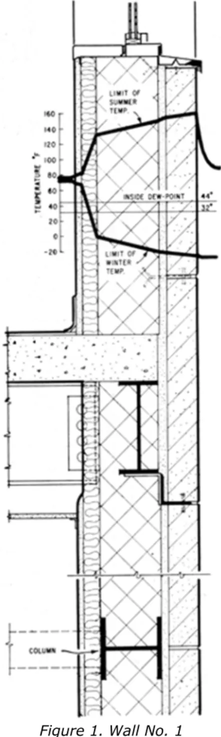
Figure 1. Wall No. 1
The calculated limiting temperature gradients for winter and summer are superimposed on the wall section. Winter conditions are assumed to be 73°F inside and -27°F outside. An indoor relative humidity of 35 per cent which might commonly be desired in winter, corresponds to a dew-point temperature of 44°F, which has been drawn on the diagram. Summer conditions are assumed to be 75°F indoors and 90°F air temperature outdoors with a surface temperature due to solar radiation of 150°F. The summer gradient is drawn for an assumed steady flow condition that is never realized in practice but does represent for present purposes a reasonable estimate of the limiting gradient conditions to be encountered.
The very large range in temperature of the back-up and cladding from winter to summer, amounting to about 160°F, may at once be noted. This produces changes in dimension in these components of about 0.1 per cent from winter to summer. The spandrel beams and columns are enclosed in the wall material outside the insulation and thus tend to follow the temperature
interior structure remains at a nearly uniform temperature and may resist the movements of the attached members which are changing in temperature. These effects lead inevitably at times to cracks in portions of both the exterior walls and cross-walls.
Penetration of the insulating layer by crossbeams, cross-walls and slabs creates thermal bridges. Cool interior surfaces may thus be produced on which condensation may form in winter unless relative humidities are kept to low values. The calculation of surface temperatures for such two- and three-dimensional cases can be very complex, but estimates may be made for some common cases with the aid of the information given inCBD 44.
Windows also suffer thermally from contact with the main portion of the wall, which is outside the insulation. The temperatures of metal frames, sills and sash in contact with cold masonry in winter are lowered, thus complicating the critical thermal condition at the window and in many cases reducing markedly the already low relative humidity that can be carried without condensation.
The thermally induced expansions and contractions of the back-up and cladding and the restraining forces exerted by various connected parts of the structure are, as already indicated very likely to lead to cracks. In addition to their visual effects, these can be serious in two ways: they may allow the leakage of warm air outwards into the wall in winter, and they may allow rain penetration at other times. It is almost impossible to predict with any certainty the occurrence, size and location of such cracks. Both reason and experience confirm that they do occur. There may in addition be many other unintentional paths for outward air leakage, particularly under windows and at roof slabs and parapets, arising from lack of attention in design or construction.
Reference to the winter temperature gradients for Wall No. 1 will show that all material outside the insulation will fall below freezing. Air leaking outward through cracks or faults will deposit moisture in the cold masonry whenever the dew-point temperature of the moisture it contains is above the temperature of the masonry. Naturally the higher the indoor relative humidity the greater will be the amount of moisture deposited, but, as may be noted, some condensation can be expected even at low indoor humidities because of the low temperature of the masonry. At times of less severe temperature, water deposited by condensation close to a freezing plane in weak mortar may promote ice lens formation and the development of strong disrupting forces within a wall similar to those produced by frost heaving in soil. Even if ice lensing does not occur, the deposition of substantial amounts of water within the wall may lead to staining efflorescence, corrosion of ties, and to degrading effects in the wall materials if subsequently frozen when wet.
Rain penetration through cracks, occurring as a result of temperature movement in the exterior cladding, can also allow the entry of water and the wetting of the wall. The use of full mortar bedding of the cladding usually results in a weak mortar and a confused drainage pattern, so that when cracking and leakage do occur water may be retained and lead to deteriorating effects when subsequently frozen.
A dramatic difference in temperature conditions and their attendant dimensional changes can be effected by moving the location of the insulation, see Wall No. 2. The main wythe and all the parts of the structure in contact with it are subjected to a much smaller range of temperatures. The possibility of disruptive dimensional changes arising from temperature effects is greatly reduced for all but the exterior cladding and, as will be discussed, these can readily be accommodated.
Figure 2. Wall No. 2
The window frame, bedded in or fastened to the warm interior wythe, is now relieved of the. substantial edge-cooling effect of the former arrangement. Advantage can be taken of the inside metal sill to collect and conduct heat to the frame, and a thermal break may be incorporated on the outside to minimize the loss of heat in winter.
The relocation of insulation by itself effects very considerable improvement in relieving the frame and inner wythe of temperature variations. If, however, the insulation is merely inserted between the main wythe and the cladding, the latter being made continuous by the use of mortar at all joints as before, two potential difficulties remain. The cladding and the main wythe will still tend to move in relation to one another in accordance with their respective temperature changes. Cracks are almost certain to form in the cladding and perhaps also in the main wythe. Further, the cladding, being more or less continuous, is likely to provide at least a partial barrier to wind pressure so that pressure differences across it can develop and cause rain to enter wherever cracks exist. The need for some further improvement in the design is thus indicated.
screen (seeCBD 40). It may be set out to form an air space and supported by ledger angles and ties as before. The air space, being heavily vented by suitably designed open joints at both horizontal and vertical intervals, will at all times follow closely the outside air pressure so that the rain screen is substantially relieved of wind pressure differences. This not only removes the major force causing rain to penetrate the cladding, but also eliminates the wind loads on it. Open joints in the cladding, that need only be arranged to prevent the direct entry of rain drops, serve also as expansion joints. Any rain that does migrate to the back of the cladding will run down and can be intercepted by suitable flashing above each ledger angle and drained to the outside.
The problem of thermal bridges has been greatly reduced, though the need for ties and ledger angle support for the cladding still remains. The metal connections between the ledger angle and the spandrel beam must be kept to the minimum necessary for structural support so as to minimize the thermal bridging; on the other hand, however, they can now be fastened to a relatively large, relatively warm high-conductivity member capable of supplying the necessary heat to make up the loss through the connection without undue reduction in temperature. Finally, corrosion of ties can be greatly improved by proper design that avoids serious or prolonged wetting.
The need for a vapour barrier and the question of the relative humidity that can be carried has still to be discussed. A vapour flow analysis, not included, indicates that Wall No. 1 will experience condensation under winter conditions with 35 per cent relative humidity indoors, while Wall No. 2 will not. The possibility of this may be gauged from examination of the winter temperature curves relative to the indoor dew-point temperature. In Wall No. 1 the temperature falls below the dew-point at a point within the insulation and is far below it for all parts of the wall outside the insulation. In Wall No. 2 the main wythe and all parts of the frame are held above 44°F. The significance of this condensation from vapour diffusion in Wall No. 1 must, however, be questioned despite the importance attached in the past to the use of vapour barriers to control such vapour diffusion. Relatively small amounts of water will be involved when the materials on the warm side are reasonably resistant to vapour flow, e.g. paint on plaster.
The possibility of condensation from vapour diffusion alone within Wall No. 1, while undesirable, does not lead to a firm basis for establishing the limiting indoor relative humidity that can be carried in winter. Actually the cool surfaces of windows and frames and of the ends of cross-beams and slabs bedded in cold outer masonry will, in the first instance establish the limit on indoor relative humidity through surface condensation. As discussed Wall No. 1 is inferior in these respects. The real danger from increased indoor relative humidity comes from outward air leakage, which carries with it water vapour to be deposited in substantial quantities by condensation in the cold outer parts of the wall with which it comes in contact.
The merits of Wall No. 2 can now be more fully appreciated. Pilot only has the possibility of cracking from movements due to thermal and moisture changes been greatly reduced but in addition the possibility of degradation caused by wetting and wet freezing has been minimized. All parts of the wall inside the insulation are kept well above the indoor dewpoint of 44°F so that no condensation should occur there. Indeed a relative humidity higher than 35 per cent might be carried with safety for the conditions assumed, so far as the wall section itself is concerned. The limitation posed by cold window surfaces and the heat bridges formed by the cladding ties and supports has been greatly relieved.
Even if condensation does occur on the warm side of the insulation, the temperature there is shown to be well above freezing, so that wet-freezing should not occur. Any water vapour or moist air moving outward does not encounter freezing conditions until it reaches the insulation. Some condensation, even if it does occur within the insulation need not be serious; it can later pass relatively freely to the air space and on to the outside.
While Wall No. 2 can tolerate condensation should it occur, it is still desirable to ensure adequate control of vapour flow and air leakage. Suitable barrier properties should be built into the wall between the inside and the insulation. Wall No. 2 presents much more opportunity for this than does Wall No. 1.
Conclusion
The modified design illustrated by Wall No. 2 will experience reduced temperature changes and reduced possibility of cracking within its main section. Movements in the cladding can be tolerated. Greater freedom is provided for the positive control of heat flow, air leakage, vapour flow and rain penetration, and at the same time the wall is inherently less vulnerable to wetting and freezing.
It must not be thought that only masonry walls are subject to the difficulties that have been discussed. Changes to other materials and types of walls do not eliminate potential difficulties, although they may change the relative seriousness of the various problems that may be encountered. These difficulties can be avoided with reasonable assurance only by an appreciation of the mechanisms involved and by careful analysis and design.