HAL Id: tel-02052912
https://tel.archives-ouvertes.fr/tel-02052912
Submitted on 28 Feb 2019
HAL is a multi-disciplinary open access
archive for the deposit and dissemination of
sci-entific research documents, whether they are
pub-lished or not. The documents may come from
teaching and research institutions in France or
abroad, or from public or private research centers.
L’archive ouverte pluridisciplinaire HAL, est
destinée au dépôt et à la diffusion de documents
scientifiques de niveau recherche, publiés ou non,
émanant des établissements d’enseignement et de
recherche français ou étrangers, des laboratoires
publics ou privés.
Model-Code Synchronization in Reactive System
Development
van Cam Pham
To cite this version:
van Cam Pham. Model-Based Software Engineering : Methodologies for Model-Code Synchronization
in Reactive System Development. Embedded Systems. Université Paris Saclay (COmUE), 2018.
English. �NNT : 2018SACLS611�. �tel-02052912�
Thèse
de
do
ctorat
NNT
:
2018SA
CLS611
Methodologies for Model-Code
Synchronization in Reactive System
Development
Thèse de doctorat de l’Université Paris-Saclay préparée à l’Université Paris-Sud au sein du CEA-LIST Saclay
Ecole doctorale n∘580 Sciences et technologies de l’information et de la communication (ED STIC)
Spécialité de doctorat : Informatique
Thèse présentée et soutenue à Gif-sur-Yvette, le 12/01/2018, par
Van Cam PHAM
Composition du Jury :
Laurent PAUTET
Professeur, Telecom Paristech Président Ileana OBER
Professeur, Université Paul Sabatier Rapporteur Antoine BEUGNARD
Professeur, IMT Atlantique Bretagne Rapporteur Laurence DUCHIEN
Professeur, Université de Lille Examinateur Franck BARBIER
Professeur, Université de Pau (LIUPPA) Examinateur Sébastien GÉRARD
HDR, Chef du laboratoire LISE (CEA) Directeur de thèse Ansgar RADERMACHER
Ingénieur-chercheur, LISE (CEA) Encadrant Shuai LI
Dedication
To
Acknowledgments
My journey to the objectives of this research work has many challenges that could not be achieved without the help of many people to whom I am indebted.
To my supervisors, Dr. Ansgar RADERMACHER, Dr. Sébastien GÉRARD and Dr. Shuai LI, I thank you from the bottom of my heart for your time, effort and advices you all have given to me. Being worked with and supervised by you is my greatest and most notable experience ever. To Ansgar, thank you very much for your thoughtfulness, distinguished and insightful technical knowledge and your detailed feedback about the thesis starting from the problem definition to the solution implementations and evaluations. To Sébastien who drives the laboratory LISE, please accept my gratitude to you for your motivation, patience, immense knowledge support and invaluable suggestions for the research subject that I have been following. To Shuai, many thanks to you for being a discussant and for giving me a lot of constructive comments; also, I appreciate your pedagogical capability that inspires me a lot.
To the Papyrus Designer team of the laboratory LISE, thank you all for helping me to resolve issues related to technical aspects during implementation. I am proud of being part of the best team I have ever had.
To the members developing the Moka engine, thank you very much for many discussions and for welcoming all of my questions that make me clarify the precise semantics of UML elements.
To all members of the laboratory LISE, thank you for creating such a friendly, productive and resourceful environment
To my friends, thank you very much for spending time talking to me and giving lots of encouragements every time I feel unmotivated.
Last, but not least, I would like to dedicate my sincere gratitude to the most important people in my life: my family. To my wife Van Anh and my newborn daughter Thao My, I love you so much and thank you for stepping into my life, always being by my side and making me happy all the time. To Dad, Mom and my younger brother, words are not emotional enough to express my thankfulness dedicating to you for your spiritual support and believing in me and your unconditional help; without you, I would not be able to keep my mind consistent in light of achieving the research.
ALF Action Language for Foundational UML. xii, 38,122,134,135 API Application Programming Interface. 23,38
AST Abstract Syntax Tree. 25
ATL Atlas Model Transformation Language. 27
DSML Domain-Specific Modeling Language. 20,24,25
EMF Eclipse Modeling Framework. 21,24,27
FSML Framework-Specific Modeling Language. 23,24
GPML General-Purpose Modeling Language. 9
IDE Integrated Development Environment. 2,3,22, 34, 38,43, 48–50, 53,55, 56, 61,62, 74,83,99
JTL Janus Transformation Language. 28
MARTE Modeling and Analysis of Real-Time and Embedded Systems. 9
MBSE Model-Based Software Engineering. 1–5,7–9,14,16,18,19,26, 28,30,35,38,39, 71,102,113,134
OCL Object Constraint Language. 26,30
OMG Object Management Group. 19,26,61, 76, 101,102,118
PSCS Precise Semantics for UML Composite Structure. xii, xiii, 76, 78, 91, 97, 101, 118–122,135
PSSM Precise Semantics for UML State Machine. xii, 103, 104, 117, 118, 120–122, 135, 141
QVT Query/View/Transformation. 4,9,26, 28, 29,111
reactive system reactive system. 14,15
TGG Triple-Graph Grammar. 4,27,28,30 TML Textual Modeling Language. 83
UML Unified Modeling Language. 2, 9, 10, 12, 14, 15, 20, 22, 23, 33–35, 37, 41, 42, 44, 45,70,75,76,80,85,89,91,94,102,104,106,108, 110,113,117,125,134 UML-Class UML class. 2,3,20,23,41
UML-CS UML composite structure. xvi,2–5, 7, 9, 10,14–20, 22–24, 31, 36, 37, 39, 41, 45,71,73,74,89,93,101,106,117–119,121,124,126,129,131,132,134–136 UML-SM UML state machine. xvi,2–5,7,9–12,14–20,22–24,26–28, 31,35–37,39,41,
45,48,71,74,75,81–84,89,102–104,111,113,117,118,121,124,125,129,131, 132,134–136,139,140,142,144
Abstract: Model-Based Software Engineering (MBSE)has been proposed as a promising software development methodology to overcome limitations of traditional programming-based methodology in dealing with the complexity of embedded systems. MBSEpromotes the use of modeling languages for describing systems in an abstract way and provides means for automatically generating different development artifacts, e.g. code and documentation, from models. The development of a complex system often involves multiple stakeholders who use different tools to modify the development artifacts, model and code in particular in this thesis. Artifact modifications must be kept consistent: a synchronization process needs to propagate modifications made in one artifact to the other artifacts.
In this study, the problem of synchronizing Unified Modeling Language (UML)-based architecture models, specified by UML composite structure (UML-CS) and UML state
machine (UML-SM) elements, and object-oriented code is presented. UML-CSs are used
for describing the component-based software architecture andUML-SMs for discrete event-driven behaviors of reactive systems. The first challenge is to enable a collaboration between software architects and programmers producing model and code by using different tools. This raises the synchronization problem of concurrent artifact modifications. In fact, there is a perception gap between diagram-based languages (modeling languages) and text-based languages (programming languages). On the one hand, programmers often prefer to use the more familiar combination of a programming language and an Integrated Development Environment. On the other hand, software architects, working at higher levels of abstrac-tion, tend to favor the use of models, and therefore prefer diagram-based languages for describing the architecture of the system. The second challenge is that there is a signif-icant abstraction gap between the model elements and the code elements: UML-CS and
UML-SM elements are at higher level of abstraction than code elements. The gap makes
current synchronization approaches hard to be applied since there is no easy way to reflect modifications in code back to model.
This thesis proposes an automated synchronization approach that is composed of two main correlated contributions. To address the first challenge, a generic model-code synchro-nization methodological pattern is proposed. It consists of definitions of necessary func-tionalities and multiple processes that synchronize model and code based on several defined scenarios where the developers use different tools to modify model and code. This con-tribution is independent ofUML-CSs andUML-SMs. The second contribution deals with the second challenge and is based on the results from the first contribution. In the second contribution, a bidirectional mapping is presented for reducing the abstraction gap between model and code. The mapping is a set of correspondences between model elements and code elements. It is used as main input of the generic model-code synchronization methodological pattern. More importantly, the usage of the mapping provides the functionalities defined in the first contribution and eases the synchronization ofUML-CS andUML-SMelements and code. The approach is evaluated by means of multiple simulations and a case study.
Keywords:
UML, model-based software engineering, architecture model, UML statema-chines, composite structures, component-based architecture, model-code synchronization, code generation, reverse engineering, software architects, programmers.
systèmes réactifs
Résumé: Model-Based Software Engineering (MBSE)a été proposé comme une gie prometteuse de développement de logiciels pour surmonter les limites de la méthodolo-gie traditionnelle basée sur la programmation pour faire face à la complexité des systèmes embarqués. MBSEfavorise l’utilisation de langages de modélisation pour décrire les sys-tèmes d’une manière abstraite et fournit des moyens pour générer automatiquement de différents artefacts de développement, p.ex. code et documentation, à partir de modèles. Le développement d’un système complexe implique souvent de multiples intervenants qui utilisent différents outils pour modifier les artefacts de développement, le modèle et le code en particulier dans cette thèse. Les modifications apportées aux artefacts évoquent le problème de cohérence qui nécessite un processus de synchronisation pour propager les modifications apportées dans l’un artefact aux autres artefacts.
Dans cette étude, le problème de la synchronisation des modèles d’architecture basés sur les élémentsUML composite structure (UML-CS)etUML state machine (UML-SM)du langage de l’Unified Modeling Language (UML), et le code orienté objet est présenté. UML-CSs sont utilisés pour décrire l’architecture du logiciel basée sur les composants etUML-SMs pour les comportements discrets liés aux événements des systèmes réactifs. Le premier défi est de permettre une collaboration entre les architectes de logiciels et les programmeurs produisant de modèle et de code, en utilisant différents outils. Il soulève le problème de synchronisation où il existe de modifications simultanées des artefacts. En fait, il existe un écart de perception entre les langages à base de diagramme (langages de modélisation) et les langages textuels (langages de programmation). D’une part, les programmeurs préfèrent souvent utiliser la combinaison familière d’un langage de programmation et d’un environ-nement de développement intégré. D’autre part, les architectes logiciels, travaillant à des niveaux d’abstraction plus élevés, favorisent l’utilisation des modèles et préfèrent donc les langages à base de diagramme pour décrire l’architecture du système. Le deuxième défi est qu’il existe un écart d’abstraction significatif entre les éléments du modèle et les éléments du code: les élémentsUML-CSet UML-SMsont au niveau d’abstraction plus élevé que les éléments du code. L’écart rend la difficulté pour les approches de synchronisation actuelles car il n’y a pas de façon facile de réflecter les modifications du code au modèle.
Cette thèse propose une approche automatisée de synchronisation composée de deux principales contributions corrélées. Pour aborder le premier défi, on propose un patron méthodologique générique de synchronisation entre modèle et code. Il consiste en des défi-nitions des fonctionnalités nécessaires et plusieurs processus qui synchronisent le modèle et le code en fonction de plusieurs scénarios définis où les développeurs utilisent différents out-ils pour modifier le modèle et le code. Cette contribution est indépendante deUML-CSs et UML-SMs. La deuxième contribution traite du deuxième défi et est basée sur les résultats de la première contribution. Dans la deuxième contribution, un mapping bidirectionnel est présentée pour réduire l’écart d’abstraction entre le modèle et le code. Le mapping est un ensemble de correspondances entre les éléments de modèle et ceux de code. Il est utilisé comme entrée principale du patron méthodologique générique de synchronisation entre mod-èle et code. Plus important, l’utilisation du mapping fournit les fonctionnalités définies dans la première contribution et facilite la synchronisation des éléments deUML-CSetUML-SM et du code. L’approche est évaluée au moyen de multiples simulations et d’une étude de cas.
entre model et code, génération de code, reverse engineering, architectes de logiciels, pro-grammeurs.
Synthèse: Cette thèse se déroule dans le contexte de l’utilisation d’Ingénierie Dirigée par les modèles pour les systèmes embarqués. L’hypothèse de la thèse est que les développeurs d’un système logiciel embarqué réactif complexe utilisent les éléments de modélisation Com-posite Structure (UML-CS) et State Machine (UML-SM) du langage UML pour concevoir le système et ils utilisent différents outils pour manipuler les artefacts de développement, le modèle et le code en particulier. Le modèle de conception et le code peuvent évoluer simultanément car les différentes pratiques, à savoir la modélisation et la programmation, modifient ces artefacts. Le problème est que, lorsque le modèle de conception et le code sont modifiés, il est très difficile de synchroniser les modifications simultanées des artefacts, car il existe un écart d’abstraction entre les éléments UML-CS et UML-SM et le code. De nombreuses approches et outils ont tenté de résoudre le problème de synchronisation des artefacts dans différents domaines, tels que la synchronisation des modèles, la programma-tion bidirecprogramma-tionnelle, la synchronisaprogramma-tion des codes de modèles, l’ingénierie aller-retour et la co-évolution de la mise en œuvre d’architecture. Cependant, ces approches ne permettent pas de résoudre le problème posé en raison de deux problèmes: (1) la gestion des modifica-tions simultanées du modèle et du code; et (2) prendre en charge la synchronisation entre le modèle et le code également pour les éléments avec un grand espace d’abstraction, en particulier les éléments UML-CS et UML-SM (qui n’ont pas de représentation directe dans les langages de programmation orientés objet).
Dans cette thèse, un ensemble d’exigences pour une approche de synchronization est ex-posé et une nouvelle approche pour le problème de la synchronisation du modèle d’architecture logicielle, spécifiée à l’aide d’éléments de modélisation UML-CS et UML-SM, et du code orienté objet est développée. L’approche proposée fait le lien entre les pratiques de mod-élisation et de programmation, permettant ainsi une collaboration transparente entre les développeurs. L’approche prend en charge la synchronisation des éléments structurels et comportementaux du modèle et du code. La démarche s’appuie sur les contributions suiv-antes:
∙ Mappage bidirectionnel entre un langage de programmation existant et des éléments de modélisation en ajoutant des constructions de programmation supplémentaires au langage existant pour les éléments de modélisation sans représentation en code.
∙ Un ensemble de modèles de génération de code permettant l’exécution de l’exécutable des constructions proposées et le débogage du code utilisateur.
∙ Un modèle méthodologique générique de synchronisation modèle-code pour permettre la synchronisation du code étendu avec le modèle d’architecture.
L’approche est mise en œuvre au-dessus de l’outil de modélisation Papyrus Software Designer. Plusieurs expérimentes sont menées pour évaluer l’approche proposée par rapport à l’ensemble d’exigences identifiées pour examiner les approches existantes. Les mécanismes de cartographie et de synchronisation bidirectionnels sont évalués en détail au moyen de multiples simulations d’éléments de diagramme de classes UML et de C ++, d’une étude de cas de l’exécution de Papyrus-RT développée en C ++ et d’une étude de cas de l’usine de voitures Lego utilisant UML. Éléments -CS et UML-SM. Les modèles de génération de code sont évalués pour déterminer si la prise en charge de la génération de code pour les éléments
de test Les suites de tests PSCS et PSSM sont affirmées; et l’efficacité du code généré en ce qui concerne les performances de traitement des événements et la consommation de mémoire: le code généré par notre modèle pour deux exemples de machines à états est rapide et nécessite une consommation de mémoire faible par rapport aux approches incluses dans le contexte de la thèse.
Mots-clés:
model-based software engineering, modèle d’architecture, machines à état,systèmes embarqués, architecture basée sur les composants, synchronisation entre model et code, architectes de logiciels.
∙ V. C. Pham, A. Radermacher, S. Gérard, and S. Li. Bidirectional Mapping Between Architecture and Code for Synchronization. In ICSA 2017 - Proceedings of the 14th IEEE International Conference on Software Architecture, Gothenburg, Sweeden, 3-7 April, 2017.
∙ V. C. Pham, A. Radermacher, S. Gérard, and S. Li. Complete Code Generation from UML State Machine. In MODELSWARD 2017 - Proceedings of the 5th Inter-national Conference on Model-Driven Engineering and Software Development, Porto, Portugal, 19-21 February, 2017.
∙ V. C. Pham, A. Radermacher, S. Gérard, and S. Li. UML State Machine and Compos-ite Structure-Based Modeling and Code Generation for Reactive Systems. Springer Communications in Computer and Information Science, 2017. to appear.
∙ V. C. Pham, S. Li, A. Radermacher, S. Gerard, and C. Mraidha. Fostering Software Architect and Programmer Collaboration. In 21st IEEE International Conference on Engineering of Complex Computer Systems, ICECCS 2016, Dubai, United Arab Emirates, November 6-8, 2016, pages 3–12.
∙ V. C. Pham, A. Radermacher, and S. Gérard. From UML State Machine to Code and Back Again! In Position Papers of the 2016 Federated Conference on Computer Science and Information Systems, FedCSIS 2016, Gdansk, Poland, September 11-14, 2016., pages 283–290.
∙ V. C. Pham, A. Radermacher, S. Gérard, and F. Noyrit. Change Rule Execution Scheduling in Incremental Roundtrip Engineering Chain: From Model-to-Code and Back. In MODELSWARD 2016 - Proceedings of the 4rd International Conference on Model-Driven Engineering and Software Development, Rome, Italy, 19-21 February, 2016., pages 225–232.
∙ V. C. Pham, Ö. Gürcan, and A. Radermacher. Interaction Components Between Components based on a Middleware. In 1st International Workshop on Model-Driven Engineering for Component-based Software Systems (ModComp’14), 2014.
1.1 Model partitioning and information containment . . . 4
2.1 Overview of the MBSE methodology excerpted from [Brambilla 2012] . . . 8
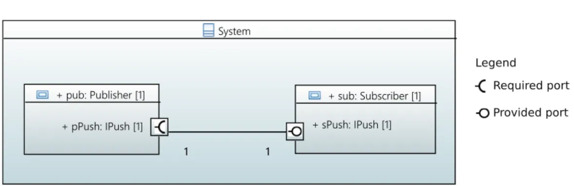
2.2 Composite structure diagram for a publisher-consumer example . . . 10
2.3 Example of a state machine excerpted from [Specification 2015]. The state machine consists of a composite state Active, 10 simple states, and 4 pseudo states including 2 initials, 1 terminate, and 1 entry point. Call-events such as lift receiver and dial digit are used. A time-event, which has a wait period of 15 seconds, triggers the transition from DialTone to Time-out. . . 12
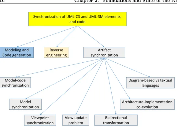
2.4 State of the art of approaches related to model-code synchronization . . . . 16
2.5 Bidirectional invariant traceability framework by horizontal bidirectional syn-chronization excerpted from [Yu 2012] . . . 25
2.6 Example of Archface excerpted from [Ubayashi 2010] . . . 33
3.1 Overview of approach and contributions . . . 39
3.2 Annotation processing in Java. . . 41
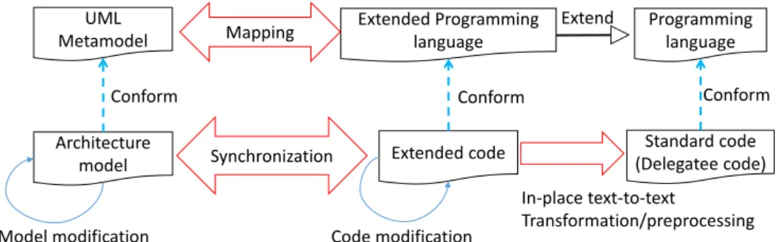
3.3 Extended code and Standard code in the same repository . . . 42
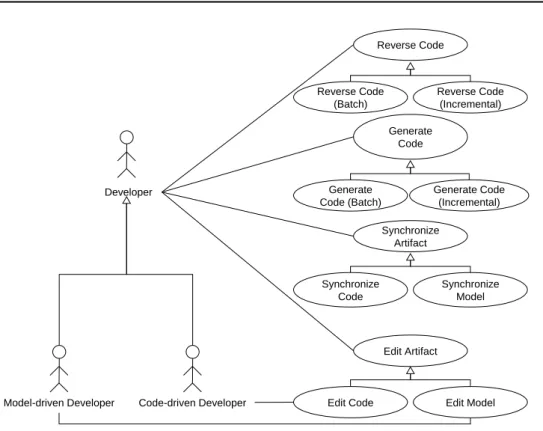
4.1 Use-cases of Integrated Development Environment (IDE) for model/code edi-tion and synchronizaedi-tion . . . 47
4.2 Batch and incremental code generation. . . 49
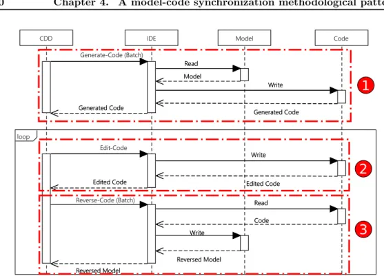
4.3 Synchronization process for scenario 1, in which only code is edited (CDD = Code-Driven Developer). The API calls for Model and Code are represented generically as "Read" and "Write". . . 50
4.4 Synchronization process for scenario 3 using the first strategy, in which the model and the code are concurrently edited with code as the synchronization artifact (CDD = Code-Driven Developer, MDD = Model-Driven Developer). The API calls for Model and Code are represented generically as "Read" and "Write". . . 52
4.5 Example of synchronizing concurrently modified model and code using the first strategy . . . 54
4.6 Example of synchronizing concurrently modified model and code using the second strategy . . . 54
4.7 Simulation 1 for Law 1 (right-invertibility). . . 60
4.8 Simulation 2 for Law 2 (left-invertibility) . . . 61
4.9 Simulation 3 for concurrent editions case. . . 62
5.1 Architecture and behavior example model . . . 67
5.2 Generated extended code example . . . 67
5.3 Composite structure diagram for a publisher-consumer example with multi-plicities for a star pattern connector . . . 70
5.4 Composite structure diagram of the producer-consumer example using flow ports . . . 72
5.5 Generated extended code for FIFO state machine example copied from Fig.
5.2 . . . 73
5.6 A concrete syntax for state machine topology in C++. For syntax of event types and transitions, see Fig. 5.7 and 5.8 for more details. 𝜆 denotes an empty string . . . 74
5.7 A concrete syntax for event declarations in C++ . . . 76
5.8 A concrete syntax for transitions . . . 78
5.9 Delegation from a component to its delegatee . . . 79
5.10 Formalization of operation of delegation from extended code to delegatee code for the producer-consumer example when a system is created from the main method . . . 81
5.11 Delegation from a component to its delegatee . . . 82
5.12 Composite structure examples of port connectors (a), and both port-port and port-port-part connectors (b). . . 83
5.13 Example of single connector for array pattern . . . 87
5.14 Example of using intermediary to bridge the connections between 𝑝 and 𝑏 and 𝑐. . . 89
5.15 Delegation connectors example with star and array pattern . . . 91
5.16 Thread-based concurrency design for state machine execution . . . 96
5.17 Example illustrating different ways entering a composite state . . . 98
5.18 Interactions between FIFO and its delegatee during processing of a signal-event102 5.19 Incremental reverse engineering with file tracker. . . 106
5.20 Semantic conformance evaluation methodology . . . 109
5.21 An example of multiple delegation with multiple port-port connectors of Precise Semantics for UML Composite Structure (PSCS) excerpted from [OMG 2015] . . . 110
5.22 An illustrative example of test cases for Precise Semantics for UML State Machine (PSSM) . . . 110
5.23 Simple state machine example from [Boost 2016b] . . . 112
5.24 Composite state machine example from [Boost 2016a] . . . 113
5.25 Event processing speed for the benchmarks . . . 114
5.26 Event processing performance in optimization mode . . . 116
5.27 Composite structure diagram of the front module for flow ports (see Ap-pendix E on page 142 for more details about design model and generated code.) . . . 118
5.28 Comparison of lines of code . . . 120
5.29 Comparison of lines of application code . . . 121
6.1 Client-server example including interaction component transformation, client-side, and server-side code . . . 126
6.2 A synchronization example of Action Language for Foundational UML (ALF) and C++ excerpted from [Ciccozzi 2016b] . . . 127
B.1 Synchronization process for scenario 2, in which only code is edited (MDD = Model-Driven Developer). The API calls for Model and Code are represented generically as "Read" and "Write". . . 132
E.1 The organization of the Lego Car application model contains 4 UML packages for 4 modules.. . . 142
E.2 The state machine diagram of the FrontControlComponent. . . 143
E.3 The CDT C++ project generated for the front module. It contains multiple folders for C++ libraries. The "Architecture Delegatee" contains delega-tee code. The "LegoCarComponents" contains extended code for the front module application model. . . 144
2.1 Requirements for model-code synchronization . . . 14
2.2 Requirements for UML-based reactive system design . . . 15
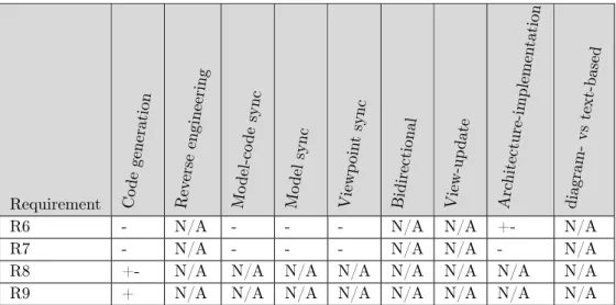
2.3 Existing approaches with respect to the model-code synchronization require-ments. R1 = Model modification propagation; R2 = Code modification propagation; R3 = Model modification preservation; R4 = Code modifica-tion preservamodifica-tion; R5 = Concurrent modificamodifica-tion. "N/A" = not applicable; "+" = support; "-" = not; "+-" = partial (either require manual intervention or produce unintended results or need significant effort if used). . . 35
2.4 Existing approaches with respect to the requirements for UML-based design. R6 = Structure completeness; R7 = Behavior completeness; R8 = UML-conformance; R9 = Generated code efficiency; "N/A" = not applicable; "+" = support; "-" = not; "+-" = partial (either require manual intervention or produce unintended results or need significant effort if used). . . 36
4.1 Model elements with same semantics . . . 59
4.2 Editions and the modifications events they trigger (A = ADDED, C = CHANGED, R = REMOVED). . . 61
4.3 Differences in Papyrus-RT runtime versions . . . 63
5.1 Mapping between UML and Extended Language and Examples-1 . . . 68
5.2 Mapping between UML and Examples of Extended Language-2 . . . 71
5.3 Model change classification and management . . . 105
5.4 Sub-test suites and the number of test cases of the PSCS test suite . . . 109
5.5 Executable size in KB . . . 115
5.6 Runtime memory consumption in KB. Columns from left to right are MSM, MSM-Lite, EUML, Sinelabore, QM, and Our tool, respectively. . . 115
5.7 Lego Car Factory with and without synchronization. Sync support (SS) denotes the code generated by the presented approach while No sync (NS) denotes the code generated by the existing approach . . . 119
A.1 UML Class and Composite Structure metamodel elements supported by the synchronization . . . 130
C.1 Equivalences between connector and binding . . . 133
1 Introduction 1 1.1 Context . . . 1 1.2 Research challenges. . . 2 1.3 Assumption . . . 3 1.4 Contributions . . . 4 1.5 Thesis outline . . . 5
2 Foundations and State of the Art 7 2.1 Foundations . . . 7
2.1.1 Model-Based Software Engineering (MBSE) . . . 7
2.1.2 Composite structure for component-based modeling . . . 9
2.1.3 UML State Machine . . . 10
2.1.4 Relations to Architecture Description ISO/IEC/IEEE 42010 standard 12 2.2 Requirements for model-code synchronization . . . 13
2.2.1 Requirements for artifact synchronization . . . 14
2.2.2 Requirements for UML-based reactive system design . . . 15
2.3 State of the Art: Literature review . . . 16
2.3.1 Modeling and code generation using UML-CS and UML-SM elements 17 2.3.2 Reverse engineering . . . 20
2.3.3 Artifact synchronization . . . 21
2.3.4 Synthesis . . . 35
2.4 Summary . . . 36
3 Overview of approach and contributions 39 4 A model-code synchronization methodological pattern 45 4.1 Collaborating actors and use-cases of synchronization. . . 46
4.1.1 Collaborating actors and development artifacts . . . 46
4.1.2 Main use-cases of IDE for collaboration . . . 48
4.2 Processes to synchronize model and code. . . 50
4.2.1 Scenario 1: code-only editions. . . 50
4.2.2 Scenario 2: model-only editions . . . 51
4.2.3 Scenario 3: concurrent editions . . . 51
4.2.4 Discussion. . . 55
4.3 An Implementation: synchronizing UML models and C++ code. . . 56
4.4 Experiments and Evaluations . . . 58
4.4.1 Simulations to assess synchronization processes . . . 58
4.4.2 Papyrus-RT runtime case-study . . . 62
4.5 Summary . . . 64
5 A bidirectional mapping and synchronization of model and code for re-active systems development 65 5.1 Bidirectional Mapping between architecture structure and behavior with code 66 5.1.1 Structural constructs. . . 66
5.1.2 Behavioral constructs . . . 73
5.2 Overview of in-place text-to-text transformation/Preprocessor. . . 78
5.3 Transformation from Component-Based to Object-Oriented Concepts . . . 80
5.3.1 Verification . . . 82
5.3.2 In-place text-to-text transformation or code generation pattern for UML-CS elements . . . 84
5.3.3 Discussion. . . 91
5.4 Transformation from state machine elements to code . . . 92
5.4.1 Features . . . 93
5.4.2 Concurrency . . . 94
5.4.3 Code generation pattern-based separation of state machine extended code and delegatee code . . . 96
5.4.4 Discussion. . . 103
5.5 Application of the synchronization mechanism by providing use-cases. . . . 104
5.6 Evaluation results . . . 106
5.6.1 Semantic conformance of runtime execution . . . 108
5.6.2 Efficiency of generated code . . . 111
5.6.3 Case study . . . 115
5.7 Summary . . . 121
6 Conclusion and perspectives 123 6.1 Conclusion . . . 123
6.2 Discussion and perspectives . . . 124
A Appendix: Subset of UML metamodel elements supported by the syn-chronization 129 B Appendix: Generic model-code synchronization methodological pattern131 C Appendix: Bidirectional mapping 133 D Appendix: Patterns for code generation from UML-SM elements and examples 135 D.1 Code generated for doActivityThread method . . . 135
D.2 Code generation for regions . . . 135
D.3 Code generation for transitions and pseudo states . . . 136
E Appendix: Lego Car Case study 141
Introduction
Contents
1.1 Context . . . 1 1.2 Research challenges . . . 2 1.3 Assumption . . . 3 1.4 Contributions . . . 4 1.5 Thesis outline. . . 5Abstract: This chapter highlights the importance and scientific challenges of the syn-chronization between model and code in the context ofModel-Based Software Engineering
(MBSE). The focus is on model elements used for reactive system development. While
synchronization is important in general and has received lots of research contributions, this chapter examines particular issues of synchronization between design model for a reactive system and code. The problem and research question are then defined. Next, the assump-tions for this research work are presented. Then, we provide a brief description of our contributions. Finally, we describe the structure of the thesis.
1.1
Context
Software programming is one of the most important activities during software development life cycle because of the increasing use of software for various purposes. Software-based systems now play a very important role in many domains.
The integration of more and more functions into software contributes to the increas-ing complexity of software-based systems, especially embedded systems. The latter are often constrained by resource infrastructure and timing requirements. An embedded sys-tem responds to stimuli from its running environment or from other syssys-tems. A reactive architecture is useful for designing flexible, loosely-coupled and scalable embedded systems [Dunkels 2006, Reactive Manifesto]. The development of software for reactive embedded systems has presented many challenges [Posse 2015]. The latter need appropriate software development methodologies to deal with. MBSEhas been proposed and considered as a promising approach to address the complexity of such systems. InMBSE, a software system is represented in terms of abstract models, which provide different views of the system to stakeholders. MBSEhas several advantages such as complexity management, model-based system analysis and automation [Selic 2012]. Generally speaking, this latter is the ability to automatically produce different artifacts such as documentation and code from models to raise software productivity and reduce software bugs.
Despite the many advantages of MBSE, there is, however, still significant reticence to adopt a fully model-centric approach [Hutchinson 2014, Selic 2012] in industrial practice. Perhaps there are several reasons that cause this reticence, such as the sharp distinction
between modeling and programming habits, the freedom of using text-based Integrated
Development Environment (IDE)s for programming compared to the very strict structure
of modeling tools, the ability to describe software behaviors in programming and modeling languages, and the tooling such port such as IDEs and version control system. In fact, there is a perception gap [Brown 2015] between diagram-based languages and text-based languages. On the one hand, programmers often prefer to use the more familiar combination of a programming language and anIDE. On the other hand, software architects, working at higher levels of abstraction, tend to favor the use of models, and therefore prefer graphical languages for describing the architecture of the system.
In order to foster the industrial adoption of MBSE, the sharp distinction between MBSE modeling and current software programming must be blurred. A process of inte-grating MBSE into current software companies, whose developers are very familiar with programming, should profit the advantages of both of the modeling and programming practices, where MBSE and programming practitioners can work together. Indeed, this vision has been motivated by different perspectives [Taylor 2007, Van Der Straeten 2008,
Cicchetti 2016]. The collaboration betweenMBSEand programming practitioners produc-ing different types of artifacts, in different languages, usproduc-ing different tools, raises the issue of artifact synchronization. InMBSE, artifact synchronization can be model synchroniza-tion, that maintains consistencies between two models, and model-code synchronizasynchroniza-tion, that maintains consistencies between model and generated code.
Among many modeling languages, UMLhas been the most widely used modeling lan-guage in MBSE [Selic 2012, Hutchinson 2014]. UML has become an industry de facto standard to describe and document the architecture of complex systems [Hilliard 1999,
Hutchinson 2014] despite the emergence and disappearance of a number of architecture de-scription languages. In addition,UML class (UML-Class),UML state machine (UML-SM),
and UML composite structure (UML-CS)diagrams and their visual representations prove
to well capture the architecture design of a component-based reactive system [Posse 2015,
Ciccozzi 2014]. Based on these observations, the focus of this thesis is to propose a model-code synchronization, where the design model is specified using UML-CSelements for de-scribing component-based software structure and UML-SMfor components’ behavior.
In fact, the survey described in [Hutchinson 2014] polled stakeholders in companies who adopt MBSEapproaches. The survey reveals that models are highly used for MBSE activities including the use of models for understanding a problem (95.2%), for team com-munication (92.7%), for capturing design (90.6%) and for code generation (88.2%). In addition, it notes that 70% of the respondents primarily work with models, but still require manually-written code to be integrated. Besides, 35% of the respondents answered that they spend a lot of time and effort merging the manually-written code to the model for avoiding the loss of this code during code regeneration from model.
In the following section, we describe our research goal and challenges.
1.2
Research challenges
Software architecture design is done at the model level by means ofUML-CSandUML-SM elements and fine-grained behavior is done at the code level. Both design model and code can evolve concurrently. The problem is stated as follow:
When both design model and code are modified, it is hard to synchronize the concurrent modifications of the artifacts because there is an abstraction gap betweenUML-CSand
UML-SMelements, and code.
Works that are strongly related to this problem include model synchronization and model-code synchronization. However, current model synchronization approaches only work under assumptions that there is an explicit traceability model between two models [Giese 2009] (not model and code) or do not consider the abstraction gap that exists between the archi-tecture design model and code. In addition, many model-code synchronization approaches only allow either model or code to be changed at a time [Van Paesschen 2005], do not propagate code modifications to model (especially partial round-trip engineering or spe-cialized comment approaches) [Kelly 2007], or do not take the UML-CS and UML-SM elements into account since there is an abstraction gap between these elements and code [Antkiewicz 2006]. The detailed discussion of these approaches will be presented in Chapter 2.
The problem is divided into the following research challenges.
Research challenge 1 (RC1) - Model-code synchronization methodology How
to synchronize the modifications of model and code while allowingMBSEand programming practitioners to work with their favorite artifact (model or code)? In traditional consid-erations, either model or code is modified and the other artifact is updated accordingly, or modifications are made in a restricted way through unfamiliar editors provided by tool vendors or separated regions. In this thesis, we address the case where both model and code can be edited concurrently by using favorite tools of model practitioners and programmers, respectively.
Research challenge 2 (RC2) - Model-implementation abstraction gap Synchro-nizing the design model specified by using theUML-CS and UML-SMelements is a chal-lenging task because there is a significant abstraction gap between the model elements and code elements [Zheng 2012]. Current artifact synchronizations are not applicable because of this abstraction gap. The synchronization can be realized if a bidirectional mapping between the model and code is established.
In the next section, we propose assumptions used in this thesis.
1.3
Assumption
We intend to solve the problem under the following assumptions:
∙ Artifiact modification: MBSE adopters (e.g. software architects) can work in a model-centric way for model manipulations while traditional programmers can con-tinue using their favorite programming environment.
∙ Fine-grained behavior code: Model can hold fine-grained behavior code (e.g. code bodies for operations or state machine actions) as blocks of texts embedded into it, e.g. UML opaque behavior. This assumption does not break existing practices with UML-based modeling tools that allow to use such capability.
∙ Information containment: Model contains more information than its associated code. The code is a view of the model because not all of the information in the model
Entire model
Code generation related-part Other information part Code Model synchronization Model-code synchronizationFigure 1.1: Model partitioning and information containment
is used for code generation and fine-grained behavior code can be embedded into model as the above assumption. Fig. 1.1 depicts the information contained by the model. This latter contains two model parts: Code generation-related part and Other information part such as information used for model-based security or performance analysis. The code is generated from the Code generation-related part. The two model parts are synchronized with each other by a model synchronization. That is to say one of the two parts might be updated correspondingly to the modifications made in the other part. Such model synchronization between the two parts is out of the scope of the thesis. Hence, we only deal with the synchronization of the code with the code generation-related model part. When we say model, we mean the code generation-related part. Except some cases we explicitly mention the two model parts. The semantics of Code generation-related part is similar to the concept of skeleton in [Seifert 2011]. This latter considers the problem of model synchronization where a model is partitioned into a skeleton part and a clothing part. The skeleton part is information that is shared between the two models to be synchronized and thus used during synchronization.
1.4
Contributions
The outcome of this research is to provide an approach for automated synchronization be-tween code and architecture model, specified by theUML-CS andUML-SMelements. More importantly, the approach targets collaboration between software architects and program-mers and allows them to work on their preferred artifact, model for the architects and code for the programmers in particular, by using their preferred language and tool.
In light of achieving this goal, we propose the following contributions for addressing the identified research challenges.
Thesis contribution 1 : In order to overcome the research challenge 1, a model-code synchronization methodological pattern is proposed. This contribution consists of defini-tions of necessary functionalities and multiple processes that synchronize model and code based on several defined scenarios where the developers use different tools to modify model and code concurrently. This contribution is independent of UML-CSs andUML-SMs and is detailed in Chapter4.
Thesis contribution 2 : The second contribution is proposed based on the results from the first contribution to deal with the challenge 2. In the second contribution, a bidi-rectional mapping is presented for reducing the abstraction gap between model and code. The mapping is a set of correspondences between model elements and code elements. It is used as main input of the generic model-code synchronization methodological pattern. More importantly, the usage of the mapping provides the functionalities defined in the first contribution and eases the synchronization ofUML-CS and UML-SM elements and code. The overview of the contributions is described in Chapter3and their details are presented in Chapters4 and5.
1.5
Thesis outline
The remaining structure of this thesis is as follows:
∙ Chapter2: This chapter provides foundations of the basic concepts ofMBSEas well as theUML-CS andUML-SM elements. It then presents a set of requirements that are identified as criteria for examining existing approaches and for validating the proposed approach and contributions.
∙ Chapter3: This chapter presents the overview of the approach for solving the identi-fied research challenges. Based on the approach, it describes where the contributions are positioned within the approach in order to provide readers a sketch of the re-search contributions. In other words, the chapter will answer the question: how are the contributions collaborated with each other to solve the problem.
∙ Chapter 4: This chapters describes the model-code synchronization methodological pattern in the first contribution where concurrent modifications of the model and the code are synchronized. This contribution addresses the RC1 research challenge.
∙ Chapter5: This chapter disseminates the second contribution that is an approach for bidirectionally mapping between architecture model specified by the UML-CS and
UML-SM elements, and code. The mapping is used as input for the synchronization
methodological pattern of the first contribution presented in Chapter4.
∙ Chapter6: This chapter concludes the thesis and discusses some perspectives related to the thesis.
Foundations and State of the Art
Contents
2.1 Foundations. . . 7
2.1.1 Model-Based Software Engineering (MBSE) . . . 7
2.1.2 Composite structure for component-based modeling . . . 9
2.1.3 UML State Machine . . . 10
2.1.4 Relations to Architecture Description ISO/IEC/IEEE 42010 standard 12
2.2 Requirements for model-code synchronization . . . 13
2.2.1 Requirements for artifact synchronization . . . 14
2.2.2 Requirements for UML-based reactive system design . . . 15
2.3 State of the Art: Literature review. . . 16
2.3.1 Modeling and code generation using UML-CS and UML-SM elements 17
2.3.2 Reverse engineering . . . 20
2.3.3 Artifact synchronization . . . 21
2.3.4 Synthesis . . . 35
2.4 Summary . . . 36
Abstract: In this chapter, we first give an overview of key concepts used as foundations in this thesis. Specifically, the basis of Model-Based Software Engineering (MBSE), the component-based modeling using UML-CS concepts such as ports and connectors, and
UML-SM elements are described. The requirements for the synchronization of code and
the UML elements are then proposed. These requirements are used as criteria for com-paring different approaches in the literature and for validating the work in this thesis. Subsequently, the state of the art of existing approaches related to the study, including reverse engineering, model-code synchronization, model synchronization, viewpoint synchro-nization, bidirectional transformation, view update problem, architecture-implementation co-evolution, diagram-based and textual languages, and code generation, is presented to show that the research challenges are not solved yet in the literature.
2.1
Foundations
2.1.1
Model-Based Software Engineering (MBSE)
MBSEis a software engineering methodology [Brambilla 2012] that focuses on creating and exploiting models. It provides views of a system to different stakeholders participating in the development of a software project. MBSEmoves the focus from programming language code in traditional programming to models expressed by elements of modeling languages. An element in a modeling language often has a graphical representation and a semantics.
Figure 2.1: Overview of theMBSEmethodology excerpted from [Brambilla 2012]
A model of a system can be used for different model-based activities such as system per-formance analysis or security analysis [Selic 2012]. InMBSE, a model that represents a software system can be automatically transformed into different artifacts such as code (im-plementation), documentation, or models conforming to another modeling language through a transformation or code generation that can be specified by specialized languages such as QVT [QVT OMG 2016] or Xtend [Bettini 2016], respectively. A transformation uses a set of rules for translating elements in one modeling language to elements in another language. Fig. 2.1 excerpted from [Brambilla 2012] shows the overview ofMBSE/MDE1 in
prac-tice, without showing the model-based analysis such as performance analysis or security analysis. The followings give the description of the concepts appearing in Fig. 2.1.
2.1.1.1 Modeling languages
A modeling language is a mean that lets engineers specify or create models for a certain aspect of a system or a complete system [Brambilla 2012]. An element of a modeling language has its clearly defined semantics and may have graphical representations and/or textual specifications. Metamodeling is the process of defining modeling languages. The detail of metamodeling is out of the scope of this thesis.
Among many of the modeling languages,UML[Specification 2015] with its different dia-grams is the most widely and extensively used for modeling software systems [Sendall 2003]. Furthermore, not just as a General-Purpose Modeling Language (GPML), UML provides means, namely profiles, for language engineers to extend theUMLlanguage itself to reuse a number of concepts defined in UML and express their concerns in the domain of the language engineers. An example of the UML extensions is the Modeling and Analysis of
Real-Time and Embedded Systems (MARTE) language for modeling and analyzing
real-time embedded systems.
1In this thesis, MBSE and MDE are considered as the same methodology that uses models as first
Among the different defined diagrams of UML, the UML composite structure
(UML-CS)and UML state machine (UML-SM)diagrams are widely used for modeling and code
generation of component-based software architecture and discrete event-driven behaviors of reactive systems [Specification 2015,Posse 2015,Ciccozzi 2014,IBM 2016a,Ringert 2014], respectively. The detailed description of these diagrams is presented in Subsection 2.1.2 and2.1.3.
2.1.1.2 Transformation
Transformations are "the heart and the soul " ofMBSE[Sendall 2003]. It is the process of taking as input one or more source models and producing as output one or more target models by applying a set of transformation rules. The latter can be specified by using a transformation language such as Query/View/Transformation (QVT) and established between the metalmodel elements of the source and target models.
Model-to-text transformation is a specialized transformation that takes models as input and derives text such as documentation or code as output. If code is produced, the model-to-text transformation is called code generation.
A transformation can be either forward or backward. A backward or reverse transfor-mation takes as input the target models produced from the source models and reconstructs the source models as output. The process of creating an abstract model from source code is called reverse engineering.
In the next subsection, we describe the concept of synchronization.
2.1.1.3 Synchronization
Once a transformation between a source model and a target model is executed, the target model can be modified for various reasons. The modifications made in the target model must be synchronized back to the source model. Synchronization is the process of keeping multiple artifacts, that share some common information, in coherence with each other. The artifacts considered in this thesis are model and code. Synchronization can either align two models (model synchronization) or a model and its generated code (model-code synchronization). This latter is the focus of this thesis.
Modifications in the target artifact can be minor or even major. In the meantime, the source model might have changed for various reasons such as for responding to new requirements. Synchronization of these concurrently modified artifacts becomes difficult and challenging when there is a significant abstraction gap between these modified artifacts [Zheng 2012].
The next subsections describe the overview of component-based architecture modeling using UML-CS diagrams and the UML-SM elements for modeling discrete event-driven behaviors.
2.1.2
Composite structure for component-based modeling
InUML, theUML composite structure (UML-CS)diagrams provide modeling elements for describing the internal structure of a class or a component and the interaction between the internal parts of a component or between a component with other components. The elements of UML-CS are very useful in modeling a component-based software structure. The following list briefly describes theUML-CS main elements.
System + pub: Publisher [1] + pPush: IPush [1] + sub: Subscriber [1] + sPush: IPush [1] 1 1 1 1 Legend Required port Provided port
Figure 2.2: Composite structure diagram for a publisher-consumer example
∙ Component: A component can be modeled as aUMLClass or aUMLComponent. It has its own structure composing port s, part s and connectors. In component-based engineering [Cai 2000], a component often serves a function of the system.
∙ Part: A part represents a role played at runtime by one or more instances of a classifier as specified by its multiplicity. A part is modeled as a composite attribute.
∙ Port: A port of a component is an interaction point between the component and its environment or between the component and its internal parts [Specification 2015]. A port can specify the services that it provides and/or the services it requires. In UML, the services are modeled as operations of interfaces meaning that a required port can request operations provided by operations of the interface of a provided port if there is a connector between them. Ports can either delegate received requests to internal parts, or they can deliver them directly to the behavior of its containing component. A port can also have a multiplicity factor.
∙ Connector: A connector specifying links enables communication between two or more instances. A connector can have multiple connector ends. Here we consider the case where a connector has only two ends. An assembly connector of a component links two or more parts or ports on parts [Ciccozzi 2016a]. A delegation connector, on the other hand, links a port p of a component to an internal part or a port on an internal part of the component. It means that what arrives at the p port will be passed on to the internal part for handling [Ciccozzi 2016a].
Fig. 2.2shows a publisher-subscriber model example. The latter has a publisher part pub with a pPush port requiring the IPush interface, and a subscriber part sub with a sPush port providing the IPush interface. The connector linking the two ports on the two parts denotes that pub can send some data to sub via the pPush port by calling the operations of IPush.
2.1.3
UML State Machine
UML state machine (UML-SM) defines a set of concepts used for modeling discrete
event-driven behavior of reactive systems. UML-SM is a significant enhanced realization of the mathematical concept of finite automaton [Rabin 1959] or finite state machines in computer science. Compared to the finite automaton, UML-SM introduces the new concepts of hierarchically nested state, orthogonal regions, state actions, transition kinds, and pseudo states. The followings describe these new concepts.
∙ Hierarchical or composite state: A composite state contains at least one region. ∙ Orthogonal regions: Regions are orthogonal to each other if they are either owned by the same state or, at the topmost level, by the same state machine. A region owns a set of vertexes and transitions, which determine the behavior flow within the region. Orthogonal regions execute concurrently if their owning state is active, meaning that multiple substates of the owning state can be active at the same time. Orthogonal regions can coordinate their execution behaviors by sending event instances to each other.
∙ State actions: A state inUML-SMcan have associated actions, namely entry, exit, and doActivity, which are executed when the state is entered, being active, and exited, respectively. The actions giveUML-SM more powerful than finite state machines in modeling complete discrete event-driven behaviors of reactive systems.
∙ Transitions: A transition in UML-SM is either external, local, or internal. The execution for an external transition exits the source state and enters the target state of the transition. Local and internal transitions are specialized transitions in UML-SM. A local transition only exists in composite states and its source and target vertex cannot be the same. The execution of a local transition does not exit its containing composite state. An internal transition is a local transition specializing that its source and target states are the same. The execution of an internal transition does not exit and re-enter its source/vertex state.
∙ Pseudo states: Pseudo states are used for chaining and coordinating multiple transi-tions. UMLdefines different pseudo state kinds and their associated visualizations and semantics. Pseudo state kinds are divided into five pairs: initial/terminate, fork/join, choice/junction, shallow history/deep history, and entrypoint/exitpoint.
Event: For modeling events, that trigger state machine transitions,UMLdefines four types of events: call-event, signal-event, time-event, and change-event, described as follows:
∙ Call-event: A call-event is associated with an operation/method and emitted if the operation is invoked.
∙ Signal-event: A signal-event is associated with UML Signal type containing data. It is emitted if the class receives an instance of the signal. When a component, whose behavior is described by a UML state machine, receives a message/signal instance through its ports, a signal-event is automatically emitted and stored in an event queue for later processing by the state machine.
∙ Time-event: A time-event specifies a wait period, starting from the time when a state with an outgoing transition triggered by the event is entered. The time-event is emitted if the state remains active longer than the wait period to trigger the transition. In other words, the state, which is the source vertex of a transition triggered by a time-event, will remain active for a maximal amount of time specified by the time-event.
∙ Change-event: A change-event has a boolean expression and is fired if the value of the expression changes from false to true. For example, a change-event can be used to detect changes of some information such as temperature measured by a sensor.
If no event is used for triggering a transition from a state, the transition is said: triggered implicitly by a completion-event. In addition, events that triggers transitions starting from pseudo states are not considered.
Fig.2.3shows a state machine example of a telephone, excerpted from [Specification 2015].
Figure 2.3: Example of a state machine excerpted from [Specification 2015]. The state machine consists of a composite state Active, 10 simple states, and 4 pseudo states including 2 initials, 1 terminate, and 1 entry point. Call-events such as lift receiver and dial digit are used. A time-event, which has a wait period of 15 seconds, triggers the transition from DialTone to Time-out.
2.1.4
Relations to Architecture Description ISO/IEC/IEEE 42010
standard
This subsection presents several common terminologies defined within the ISO/IEC/IEEE 42010 Systems and software engineering — Architecture description international standard [ISO 2011] and relates them to this thesis. The purpose is to provide to readers a conscious understanding during reading the thesis. In fact, the ISO/IEC/IEEE 42010 standard defines many concepts related to architecture description. We only extract the concepts that are the most relevant to the thesis. The definitions of the extracted concepts are given as follows.
We first define Concern as follow.
Definition 1 (Concern) A concern is any interest in a system relevant to one or more of its stakeholders [ISO 2011].
This thesis focuses on the purpose, structure and behavior concerns of the architecture. The structure and behavior can appear at the architecture as well as implementation level,
depending stakeholders who are interested in these concerns. The concept of stakeholder can be defined as follow.
Definition 2 (Stakeholder) Stakeholders are individuals, groups or organizations hold-ing Concerns for the System of Interest. Examples of stakeholders are: client, owner, user, consumer, supplier, designer, maintainer, auditor, CEO, certification authority, architect, developer [ISO/IEC/IEEE].
For a collaboration between stakeholders in this thesis, we focus on two specific types of stakeholders: software architects who use models to describe their concerns (structure or behavior) and software programmers who mainly work with code to realize the structure and behavior at a finer granularity.
In order to define the concept of Architecture Model, the definition of Model Kind is first given as follow.
Definition 3 (Model Kind) A Model Kind defines the conventions for one type of mod-eling.
In the terms of the ISO/IEC/IEEE 42010 standard, examples of model kinds include
UML class (UML-Class) diagrams, Petri nets, UML-CS and UML-SM models. We now
give the definitions of Architecture Model, Architecture View, and Architecture Viewpoint.
Definition 4 (Architecture Model) An architecture model uses modeling conventions appropriate to the concerns to be addressed. These conventions are specified by the model kind governing that model.
Definition 5 (Architecture View) An Architecture View expresses the architecture of the system from the perspective of one or more Stakeholders to address specific Concerns, using the conventions established by its viewpoint.
Definition 6 (Architecture Viewpoint) An Architecture Viewpoint is a set of conven-tions for constructing, interpreting, using and analyzing one type of Architecture View. A viewpoint includes Model Kinds, viewpoint languages and notations, modeling methods and analytic techniques to frame a specific set of Concerns.
Following these definitions supplied by the ISO/IEC/IEEE 42010 standard, aUML-CS diagram or aUML-SMdiagram is an architecture model. In addition, an architecture view is composed of one or more architecture models. It is somewhat different from the meaning of architecture/design model used in this thesis. On the one hand, we consider that an architecture model consists of UML-CS and UML-SM model elements in this thesis. On the other hand, if we consider 𝑈 𝑀 𝐿 − 𝐶𝑆∪𝑈 𝑀 𝐿 − 𝑆𝑀 as a single Model Kind, the architecture model in this thesis and that of the ISO/IEC/IEEE 42010 standard can be considered as having the same understanding.
In the next section, requirements for synchronization of the UML elements and code are identified.
2.2
Requirements for model-code synchronization
This section identifies requirements for synchronization of theUML-CS andUML-SM ele-ments and code forreactive system (reactive system)development. This step is important
Table 2.1: Requirements for model-code synchronization
ID Requirement Description
R1 Model modification
propagation
If a modification in model is relevant to code, it must be reflected to code
R2 Code modification
propagation
If a modification in code is relevant to model, it must be reflected to model
R3 Model modification
preservation
If a modification in model is irrelevant to modifications in code, it must be preserved during propagation of the code modifications back to the model
R4 Code modification
preservation
If a modification in code is irrelevant to modifications in model, it must be preserved during propagation of the model modifications to the code
R5 Concurrent
modifica-tion
If there are concurrent modifications in model and code, the modifications must be synchronized to keep the model and the code consistent
because the identified requirements are used for assessing how far the support of an ap-proach or a tool for the model-code synchronization for reactive system development is, and what is missing with the existing approaches found in the literature. Furthermore, the requirements are also a useful means for validating our contributions presented in Chapters 3,4and 5.
Tables2.1and2.2show our requirements for synchronization ofUML-CSandUML-SM elements, and code for reactive system. The requirements are divided into two groups. The first group is related to requirements for artifact synchronization in general. The second is specific toUML-based design forreactive systemdevelopment. We specify these requirements in the following definitions.
2.2.1
Requirements for artifact synchronization
Requirement 1 (Model modification propagation - R1) Model modification propa-gation requires that changes made in the model, relevant to the code, must be reflected to the code by the synchronization.
Requirement 2 (Code modification propagation - R2) Code modification propaga-tion requires that changes made in the code must be reflected to the model by the synchro-nization.
The R1 and R2 requirements are derived from the propagation property of the model synchronization in [Xiong 2007], the PUTGET property in [Foster 2007], and the consis-tent condition of relational views in [Bancilhon 1981]. On the model side, by relevant, we mean that changes made to model elements that are used for code generation should be propagated to the code. Otherwise, changes irrelevant to code generation make no effect to the code. For example, changing the value of a stereotype attribute used for model-based performance analysis is irrelevant to the generated code.
Requirement 3 (Model modification preservation - R3) Model modification preser-vation requires that the propagation of code modifications should preserve model elements, which are modified by some MBSEadopters and are not relevant to the code modifications.
Table 2.2: Requirements for UML-based reactive system design
ID Requirement Description
R6 Structure
complete-ness
Synchronization supports UML class and composite structure elements, especially ports and connectors of the latter
R7 Behavior completeness Synchronization supports UML state machine elements
R8 UML runtime
exe-cution compliance
(UML-conformance)
Runtime execution of code generated from UML state machines complies with the UML specification for UML state machines
R9 Generated code
effi-ciency
The performance and memory usage of generated code
Requirement 4 (Code modification preservation - R4) Code modification preserva-tion requires that the propagapreserva-tion of model modificapreserva-tions should preserve code elements, which are modified by some programmers and are not relevant to the model modifications.
The R3 and R4 requirements are similar the model synchronization preservation prop-erty in [Xiong 2007]. These requirements guarantee that modifications made in model (code) are kept intact during the propagation of modifications in code (model) to the model (code) if the modifications in the model and in the code are not in conflict.
Requirement 5 (Concurrent modification - R5) Concurrent modification requires that if model and code are both modified, the synchronization should bidirectionally propagate the modifications between the artifacts to make them consistent again.
2.2.2
Requirements for UML-based reactive system design
The five above requirements are similar to those of artifact synchronization in general. The following definitions give requirements specifically dedicated to the synchronization of code and model specified byUML-CS andUML-SMelements for embedded systems.
Requirement 6 (Structure completeness - R6) Structure completeness requires that model-code synchronization must synchronize model and code if structural elements, class structure andUML-CS elements in model, are concurrently modified.
Requirement 7 (Behavior completeness - R7) Behavior completeness requires that model-code synchronization must synchronize model and model-code if behavioral elements, class opera-tion and state machine elements, are concurrently modified in model and code.
The R6 and R7 requirements allow the structure and behavior of a system can be modified both at the model and the code. These requirements give flexibility and equality between modeling and programming habits and potentially benefit from advantages of these practices.
Requirement 8 (UML runtime execution compliance - R8) UML runtime execution compliance requires that the runtime execution of generated code conforms to the semantics defined by model.
Synchronization of UML-CS and UML-SM elements, and code Modeling and Code generation Model synchronization Viewpoint synchronization View update problem Architecture-implementation co-evolution Diagram-based vs textual languages Model-code synchronization Reverse engineering Bidirectional transformation Artifact synchronization
Figure 2.4: State of the art of approaches related to model-code synchronization
R8 is a must-hold requirement to assure that the generated code conforms to what is created in the model. The code must respect the semantics of structural and behavioral elements, theUML-CS andUML-SMelements in particular.
Requirement 9 (Generated code efficiency - R9) Generated code efficiency requires that generated code must be efficient: fast in event processing and little in memory con-sumption.
This thesis is to provide model-code synchronization support for embedded systems. It is then the efficiency of the code, including event processing speed in reactive system and memory consumption, must be important.
In the next section we show literature review of existing approaches for solving the problem(s) in this thesis.
2.3
State of the Art: Literature review
This section reviews different approaches proposed in the literature. The purpose of this review is to show that the research challenges identified in this thesis are not solved by the existing approaches.
The synchronization of code and UML-CS and UML-SM model elements is related to different research categories. Fig. 2.4 shows the categorization of approaches in the literature related to the problem presented in this thesis. First, the synchronization includes basic themes of software engineering, namely, forward engineering and reverse engineering. Forward engineering in MBSE is particularly composed of different steps, which create a software design model at a high abstraction level and refine the model to a detailed level
![Figure 2.1: Overview of the MBSE methodology excerpted from [Brambilla 2012]](https://thumb-eu.123doks.com/thumbv2/123doknet/12704277.355780/29.892.167.713.177.473/figure-overview-mbse-methodology-excerpted-brambilla.webp)
![Fig. 2.3 shows a state machine example of a telephone, excerpted from [Specification 2015].](https://thumb-eu.123doks.com/thumbv2/123doknet/12704277.355780/33.892.207.670.270.629/fig-shows-state-machine-example-telephone-excerpted-specification.webp)
![Figure 2.5: Bidirectional invariant traceability framework by horizontal bidirectional syn- syn-chronization excerpted from [Yu 2012]](https://thumb-eu.123doks.com/thumbv2/123doknet/12704277.355780/46.892.301.627.167.410/bidirectional-invariant-traceability-framework-horizontal-bidirectional-chronization-excerpted.webp)