HAL Id: in2p3-00996662
http://hal.in2p3.fr/in2p3-00996662
Submitted on 3 Apr 2020
HAL is a multi-disciplinary open access
archive for the deposit and dissemination of
sci-entific research documents, whether they are
pub-lished or not. The documents may come from
teaching and research institutions in France or
abroad, or from public or private research centers.
L’archive ouverte pluridisciplinaire HAL, est
destinée au dépôt et à la diffusion de documents
scientifiques de niveau recherche, publiés ou non,
émanant des établissements d’enseignement et de
recherche français ou étrangers, des laboratoires
publics ou privés.
The operation of the GANIL control system
M. Promé, L. David, E. Lécorché, T.T. Luong, L. Martina, M. Ulrich, J.C.
Labiche, J.M. Loyant, F. Loyer, S. Leveel, et al.
To cite this version:
M. Promé, L. David, E. Lécorché, T.T. Luong, L. Martina, et al.. The operation of the GANIL
control system. Tenth International Conference on Cyclotrons and their Applications, Apr 1984, East
Lansing, United States. pp.555-558. �in2p3-00996662�
p a t < < û ? ^
A
THE OPERATION OF THE GANIL CONTROL SYSTEM
M. Promé, L. David, E. Lécorché, T.T. Luong
M. Martina, M. Ulrich (Control Group)
J.C. Labiche, J.M. Loyant, F. Loyer
S. Leveel, J. Sauret (Operation Group)
THE OPERATION OF THE GANIL CONTROL SYSTEM
M. Prone, L. David, E. Léeorché, T.T. Luong, M. Martina, M. Ulrich (Control Group) J.C. Labiche, J.M. Loyant, F. Loyer, S. Leveel, J. Sauret (Operation Group)
GAHIL - CAEN - FRANCE
ABSTRACT
When the first GAHIL beaas were obtained the con trol system was operating in an elementary way ; the system behaved almost like a hug» multiplexer. How a large number of programs have been written ; they al low to take benefit of the full power of the compu ters ; they help the operators for starting, tuning and monitoring the accelerator. The paper gives a general description of these programs which are executed on the central computer : it shows how the accelerator is con trolled either directly or via dedicated microproces sors. Informations are also given on the alarm system.
1. GENERAL INFORMATIONS ON THE CONTROL SYSTEMS The GANIL control system has been described else where '.a,3,it However it seems useful to summarize its main features, that have to be known to use it proper ly. Data Bass MITRA 125 mlmeomptiUf
s
'r-LX-,'
^
J U M 1 0 ftkrt#rKMMf'r-LX-,'
J CAN 10 •tfcrcprtctsnf J U M 1 0 ftkrt#rKMMf t uHiiH^^ai 1 | •ausstaiastt I J CAN 10 •tfcrcprtctsnf/ \
| Huipanl t [ KVip«a
| C M . |Fig. 1 ! Logical structure of the control system. The logical structure of the control system is shown on figure 1. Two kinds of processors appear on that figure : one minicomputer and several microproces sors (which include an Intel 8090 chip). Actually there are 15 microprocessors : 6 of thea control the console, while the 9 others are devoted to special subsystems like RF cavities, phasing mechanisms and beam data col lection. These microprocessors perform local tasks which would take too much time of the HITSA 125 if -they were treated by this minicomputer.
What is referred to as equipment on figure 1 is es sentially an elementary device : a power supply, a mo tor, a current on a target and so on. At the present time about 1500 equipments are directly connected to the minicomputer : each of which is the object of a special entry in the data base ; each of these equip ments is known from the operator by its "operational name",a string of 16 characters chosen so as to be self explaining. The physical connections between the mini computer, the microprocessors and the equipments invol ve serial Camac loops ; hence they differ deeply from what is shown in figure 1 ; however- fro» the operator point of view figure 1 stresses an important point : the control system is a centralised one i every infor mation through it involves the minicomputer ; there is no direct link between microprocessors. For instance an operator request for controlling an equipment connec
ted to a microprocessor is first transmitted to the MITRA 125, which will know f-om its data base what to do to perform the requested ope ition.
Special attention must be paid to the following point : if the operator has only requested to read an information immediately available to the microprocessor, he will get the answer quickly if he has requested to perform a complicated process, -he final answer may come after several minutes ; it is strongly advised that .the microprocessor be programmed so as to send from time
to time "soothing" messages to let the operator know that the process is under way.
Fig. 2 : The main console.
The main console is shown on figure 2, while figure 3 shows a movable console, a subset of the main conso-le. It must be pointed out that there is no alphanume-ric keyboard on the consoles, only small numealphanume-ric ones to enter digital values. The operator has never to deal with syntaxic problems ; neither has he to memorize ope-rational names ; taking benefit of a large number of touch panels, the console proposes sets of names bet-ween which the operator chooses with a single finger. It mu»t be understood that an operator request general-ly implies that the operator touch sequencialgeneral-ly several knobs or pseudo-knobs ; all the sequence is controlled by the console microprocessor, which sends a message to the minicomputer only when the sequence is finished, and only if it is considered as being coherent.
The consoles offer several facilities. Of course one can control the equipments individually, on the basis of one knob on the console controlling one equip-ment:.. It'was the way the accelerator was tuned during the first few weeks of its operation. This tedious pro-cedure is now replaced by global operations involving tasks that can be executed on the minicomputer at the operator request. More than 100 tasks are now avai-lable ; they are considered as being only the first layer of the software needed to operate the accelerator quickly and confortably. We are going to give more in-formations on 3 classes of tasks : starting, tuning and surveying tasks. Then we will explain what are the other facilities available on the console : the signal observation system, the synopses, the alarm screen.
2. INITIAL SETTIHQ
An off-line Fortran code named PARAM computes the various parameters necessary to start the machine and the main beam characteristics, stores the results on MITRA disk-file for use by" bn-Oine tasks.
Each equipment can be controlled one by one with a shaft encoder. But because of their large number of them and the complexity of some dedicated subsystems, specific tasks have been written to set quickly the various parameters with a high degree of reproducibi-lity.
- The power supplies (about 220 regulated current power supplies, those of the experimental areas not included) are automatically switched on and set to the nominal values, previously logged on the computer disk-file, with different user tasks :LIGNE for the beam-line quadrupoles and steerers, ALC1C2 for the SSC's trim coils, ALIE for the injection and ejection ele-ments, HAFOL for the injector trim coils. Interactive facilities allow a section by section control and re-levant messages appear on the TV screen for operation guidance. For the beam-line deviation magnets, the auxiliary coils are first set to the nominal value and then a cycling procedure is performed on the main CBil by the specific task CÏCDIP.
The main magnetic field of the SSC's is first cy-cled under the control of a dedicated microprocessor, the other pover-supplies (trim coils, injection and ejection elements) are set up only when the final main coil current is reached.
- The two SSC magnets are balanced with the
rou-tine EQUSEC which moves U Hall probes through the yoke,
measures the field level at the reference radius of 2.330 • on the four sector axis, computes and sets the current in each auxiliary coil to balance or to reach the field level introduced as an input for each sector, with an accuracy of ± lgauss.The Hall gaussmeters ere on-line controlled and use a 6809 microprocessor to inter-poJAte in a calibration table : an adequate field value is then directly sent to the main computer.
- The six RF systems? are controlled by four local microprocessors (one per cyclotron and one for the
buncher) which keep the main computer informed of their operation. Specific codes named U H F for the injector, R1HF for the buncher, C1HF for the two RF cavities of SSCI and C2HF for the two cavities of SSC2 allow va-rious actions : starting and stopping the HF, reading
the status, adjusting the dee voltage.
The RF phase system is centralized for all resona-tors and is also controlled by a dedicated micropro-cessor. Phase adjustemeuts on the different cavities are done with an user task : FASP0T.
3. AUTOMATIC BEAM OPTIMIZATION
The development of computer optimisation procedu-res requiprocedu-res a perfect knowledge of the relation bet-ween machine parameters and beam properties and a highly dependable beam diagnostic system. From the starting of the GAHIL accelerators some algorithms which correlate parameters to beam properties have been successfully tested and are now used for operation and for beam studies.
The main tuning procedures used for the SSC's such as beam alignment at injection, isochronization, beam centering, optimization of RF parameters and some others operating tasks such as : buncher phase adjus-tement, beam profiles control and display, beam emit-tance limitation are briefly described.
3.1 Beam alignment at injection
By varying a steering magnet current the half beam intensity is measured successively on the right side and on the left side of the diagnostic sensor located at the SSC1 or SSC2 input. The best beam alignment is then obtained for the half-sum of these two current values. Using this method the task INCSS automatically aligns the beam at the input of each SSC.
3.2 Field correction
An interactive routine ISOGR0 developped to opti-mize the isochronism or another phase law inside the SSC's has been previously described . Last improv-ments obtained are presented in another paper of this
g
conference . So the computer aid and the main console facilities used in this program are just recalled in this paper.
The 15 beam central phase measurements along a val-ley axis controlled by a microprocessor are displayed on the TV screen. Observing the shape of the curve and taking into account some simple criterea an interactive dialogue leads the operator to choose vhat parameter has to be optimized :
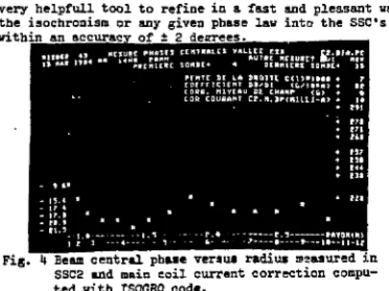
- a linear radial dependence of the central phase can be corrected by adjusting only the main magnetic field. The operator chooses the option "NIV" and two probes to delimit the radius range for the treatment. The code computes the slope of the best straight line fitting the measured points and gives in mA the needed change on the main coil current to have a flat curve as shown on figure U.
- the trim-coil currents can be adjusted so that the law "phase versus radius" follows an theoretical curve given in the program. The operator points the cursor on the option "ISO", chooses the radius range and the degree of polynomial used to fit the experi-mental curve. In few minutes, the code computes the nev trim coils currents according to the method described
7
in . A new measurement is proposed to check the effect on the nev beam and to proceed inItuning the accele-ration if necessary. This task has been running since the starting of SSCI in June 82 and proves to be a
very helpfull tool to refine in a fast and pleasant way the isochronism or any given phase law into the SSC's within an accuracy of t 2 degrees.
Fig. I» Beam central phase versus radius measured in SSC2 and main coil current correction compu-ted with ISOGRO code.
3.3 Beam centering
Magnetic field being established and then isochro-nized a* described in § 2, 3.2 a slight unbalancing can remain which gives a beam off-centering. The interae-, active on-line task TROPIC moves successively the ra-dial differential probes along the axis of the k see-tors. The acquisitions of the beam current are treated and lead to the turn characteristics such as the center of gravity of the successive turns, their radial width, the turn separation. The results obtained for each probe are stored on the MITRA disk-file and are dis-played on the TV screen. Then another task named CENTRE uses all these data to compute the corresponding cor-rections on the auxiliary and "nose" coils according to the method described in9. Fig. 5 presents the re-sults obtained with the oxygen beam accelerated at the energy of 95 MeV/A. For this'example the. beam . off-cen-tering in sectors D and B corresponds to an unbalancing AE/B of ± 5.10 *. In this case no correction is needed either on sectors C and A or in the injection area with "nose" coils. The complete treatment which has to be performed for each new case of acceleration takes about 2 hours : generally only one iteration is needed.
• t o n ? a H MI u n » nui 4in» cist MET mi- LEI. .
amnennsii s»« U HIIIE S I " nnsisniiE i oui no»
DB/B (10~') s e c t o r D
•V
Y../""YV I
s e c t o r C
t . i
-ECHOlf Dl I > I. I U S tC-C
nsuHisnTia IB naaat «<«•••» • i raw £ t'a: a n<n_..
Fig. 5 : Magnetic field defects computed by the task CENTRE which can be corrected with auxiliary coil currents.
3.U Optimisation of the RF phase and extraction turn centering
Using the beam central phase measurements in the beam lines the RF phase of SSCI or SSC2 is computed by the task FHAREQ according to the method described in" ; this precalculated value is accurate enought to inject
and accelerate the beam. Then another task named PÏCHEJ moves a probe just in front of the ejection electrosta-tic deflector, measures the current wi-ch a step of one mm and displays the peaks on the TV screen as shown on Fig. 6. By observing the shape and the position of the peaks the operator can select what parameter has to be changed, the RF phase or the RF voltage, to obtain the best turn separation or to center the last turn just on the deflector axis.
Fig. 6 ! Last turn» in SSC2 displayed with PICNEJ code for two values (points and stars) of the RF dee voltage.
3.5 Buneher HF phase adjustment
According to the method described in the code CALGR1 performs all the measurements necessary to adjust the buncher phase.
3.6 Beam profile grids and beam slits monitoring - The task COPROF controls section by section the large number of profile grids (about 100) placed along the beam-lines between the 3 cyclotrons and on the expe-rimental areas. To the operator request, the beam-line is drawn on a TV screen together with the profile grid po-sitions.
- For each grid tfc- dedicated microprocessor per-forms the current acquisitions on the grid wires and computes the profile area, th~ beam center, the width in the horizontal and vertical planes. The numerical values are sent to the central computer where different codes display these results : for example the code ORAFAI dis-plays the beam centers compared to the optical axis and the vertical and horizontal beam envelopes.
- Six pairs of slit3 are located in 3 points of the beam-lines to limit the vertical and horizontal beam emittances. The code LIMEMI moves these dedicated slits to achieve the beam emittance values given as an input by the operator. This task is also very useful to adjust properly the beam intensity on the physicist target.
r
k. SURVEYING TASKS
As an addition to the alarm system (§ 7) some user tasks have been written to find quickly where and on what equipment something is running wrong.
- For each SSC the task CINEJ displays on the TV screen the beam losses measured, every 300 ms, on the injection and ejection diagnostic sensors. This code is also useful to optimize the injection and ejection para-meters .
- For the RF phases a warning alarm is sent on the dedicated screen and the code ETAFAS, executed at the operator request, gives the complete btatus of the 6 RF cavities and the nominal values.
- For the RF dee voltage and the power supply values
a task named OBSERV reads all these parameters and com pares their values to the nominal ones previously saved on the computer disk-file by another code : STOFAH, She list of the abnormal parameters is vritten on the TV screen.
5. THE SIGNAL OBSERVATION SYSTEM
About 300 analog signals can be displayed on oscil loscopes in the control room. Most of them coma from the beam profile monitors1 0. They provide a very conve nient mean of controlling visually the beam size and position. The signals are transmitted from the monitors via the so called "Signal Observation System", a subset of the system designed at CERN for the P S1 1. Here again touch panels are used to assign any of the signals to any of the scopes. It must be mentioned that the signals from, the profile monitors are also digitized by micro processors, and can be accessed by programs executed on the «inicomputer.
6. SYNOPSES
Even if they are not essential for the accelerator operation, they provide the confort that helps the ope rator's every day life. Displayed on color TV screens, they consist of a fixed background, plus refreshed parts, that can be either numerical values or graphic symbols. Of course red is used to draw the operator's attention on elements being in an abnormal situation. As an example, figure 7 shows the trim coils in one sec tor of the SSCI. Their currents «re displayed on the right part of the figure, while the color oi' the trim coils reminds the operator which ones are in series . with the other sectors, and which ones are not.
7. THE ALARM SYSTEM
The general philosophy of the control system is that it is idle if not asked from the consoles to do some thing. Equipments, process microprocessors, are basi cally slaves that only answer or obey to the minicompu ter.
One big exception to that rule is the alarm system, by which an equipment, à process microprocessor, on "Its own initiative can send a short message to the minicom puter.
From the hardware point of view, alarms are Caaac Look-At-Me. The adress of the LAM source is used to find in the data base the text of a message to be dis played on the alarm screen, on the basis of one line edited for each alarm.
Some of them are simple warnings, others require im mediate attention from the operator (a tripped power supply results in a lost of the beam). Color code helps to distinguish between alarms.
S. CONCLUSION
One can say that the first year of operation has been a year of completion for the control system J the number of equipments known by the data base has doubled; it is still growing as the experimental areas are progressively equipped.
The hardware (mainly Camac) and the basic software can be considered as stabilized. (Basic software refors to the system software that has been written to take care of the Camac, the consoles, the process micropro cessors ).
Still rapidly growing is the application software : the tasks needed to help the operator. As this software is being developped, some limitations of the control system appear.
First the MITRA 125 is now felt as being too slow and provisions have been made to replace it by a faster com puter. In the same.time, theV.disks .will be .replaced by much larger ones.
Second, some of the JCAM 10 microprocessors are considered as bottle necks, from two points of view. First, a general consideration is that they are very slow to program, since they have been programmed in as sembler. Second, some of them (mainly the console micro processors) are not quick enough. That ia the reason why we are now developping new microprocessors, built around a M68000 which will be programmed in M B , the real time structured langage which is already used to program the minicomputer.
Third, as the application software becomes more and more sophisticated, needs have appeared for high reso lution color graphic screens. Since such peripherals were not available when the system software has been devised, additional software will be written to handle them.
REFERENCES
1. M. Promé "The Oanil Control System" IEEE. Transac tion on Nuclear Sciences vol NS-28 n° 3 June 8l p.
2369-2. P. B&rdon and al. "The OANIL Control System as seen from the control room "Proceedings of the Ninth International Conference on Cyclotrons and their Applications 1981 CAEN-France p. 609-3. L. David and al. Proceedings of the Conference
"Real Time DATA 82" VERSAILLES - November 1982 P- 179.
k. Operation Group and Computer Control Group "GANIL beam setting methods using on-line computer codes" Proceedings of the Conference "Computing in Acce lerator Design and Operation" 1983 - BERLIN (west) To be published by SPRINGER Verlag.
5. A. Joubert, B. Ducoudret, J. C. Labiche, J. M. Loyant "Main Results on the RF Amplitude and Phase Regulation Systems in Operation at OANIL" This Conference.
6. J. Sauret and GANIL Group "Magnetic field setting and Automatic Isochronization in the GANIL SSC's" Particle Accelerators - Tome 1 - PROTVINO URSS 9ct 82.
7. J. M. Loyant, F. Loyer, J. Sauret and the Control and Theory Groups "The Computerized Beam Phase Measurement Systems at GANIL - Its Applications" Proceedings of the Conference : "Computing in Ac celerator Design and Operation" 1983 BERLIN (west) To be published by SPRINGER Verlag.
8. A. Chabert, F. Loyer, J. Sauret "Beam Tuning and Stabilization Using Beam Phase Measurement's at GANIL" This Conference.
9. "Status Report on GANIL" Particle Accelerator Con ference. IEEE Transactions on Nuclear Sciences August 83. Vol NS-30 Number I» p. 2102.
10. F. Loyer and al. "Main beam diagnostics at OANIL" Proceedings of the Ninth International Conference on Cyclotrons and their Applications - 1981 - CAEN France p.
585-U . S . Battisti and al. "A Flexible Wide-band Analog Network for Direct Signal Display on Operator Consoles" IEEE. Transaction on Nuclear Sciences Vol NS-28 n° 3 June 1981 p. 2189