HAL Id: hal-01266179
https://hal.inria.fr/hal-01266179
Submitted on 23 May 2016
HAL is a multi-disciplinary open access
archive for the deposit and dissemination of
sci-entific research documents, whether they are
pub-lished or not. The documents may come from
teaching and research institutions in France or
abroad, or from public or private research centers.
L’archive ouverte pluridisciplinaire HAL, est
destinée au dépôt et à la diffusion de documents
scientifiques de niveau recherche, publiés ou non,
émanant des établissements d’enseignement et de
recherche français ou étrangers, des laboratoires
publics ou privés.
Distributed under a Creative Commons Attribution| 4.0 International License
Multi-Resolution Meshes for Feature-Aware Hardware
Tessellation
Thibaud Lambert, Pierre Bénard, Gael Guennebaud
To cite this version:
Thibaud Lambert, Pierre Bénard, Gael Guennebaud. Multi-Resolution Meshes for Feature-Aware
Hardware Tessellation. Computer Graphics Forum, Wiley, 2016. �hal-01266179�
EUROGRAPHICS 2016 / J. Jorge and M. Lin (Guest Editors)
Volume 35 (2016), Number 2
Multi-Resolution Meshes for Feature-Aware Hardware Tessellation
Thibaud Lambert1,2, Pierre Bénard1,2, Gaël Guennebaud1,2
1Inria Bordeaux Sud-Ouest, France 2LaBRI (UMR 5800, CNRS, Univ. Bordeaux), France
Abstract
Hardware tessellation is de facto the preferred mechanism to adaptively control mesh resolution with maximal performances. However, owing to its fixed and uniform pattern, leveraging tessellation for feature-aware LOD rendering remains a challenging problem. We relax this fundamental constraint by introducing a new spatial and temporal blending mechanism of tessellation levels, which is built on top of a novel hierarchical representation of multi-resolution meshes. This mechanism allows to finely control topological changes so that vertices can be removed or added at the most appropriate location to preserve geometric features in a continuous and artifact-free manner. We then show how to extend edge-collapse based decimation methods to build feature-aware multi-resolution meshes that match the tessellation patterns. Our approach is fully compatible with current hardware tessellators and only adds a small overhead on memory consumption and tessellation cost.
1. Introduction
For real-time applications, complex geometric models are usu-ally rendered by mean of level-of-details (LOD) [LWC⇤02]: input
meshes are adaptively downsampled to satisfy a view-dependent error criterion. They are iteratively simplified during a preprocess-ing stage, and stored in a compact representation amenable for fast LOD rendering. Progressive Meshes [Hop97], and their extensions to deal with triangle strips [EAV99,SP03], are the most famous examples of such representations. They allow fine-grain control of the vertex density, but even parallel GPU implementations [LSH10] cannot leverage the full power of modern graphics hardware.
Current GPUs expose a dedicated tessellation unit allowing to amplify the polygonal density of a mesh on the fly. Each input patch (a triangle or a quad) can be subdivided at an arbitrary and contin-uous level [Mor01] enabling patch-grain LOD control with smooth spatial and temporal transitions (Figure1). In this context, the in-put geometry is often decomposed into a coarse base mesh and a displacement map from which the positions of the vertices gen-erated by the tessellation engine are reconstructed [TBB09]. This decomposition also enables fast animation by applying costly de-formations to the coarse mesh only.
Enabling continuous transitions between tessellation levels while avoiding both popping and swimming artifacts is a recurrent issue when rendering displaced LOD with hardware tessellation (Figure2). Schäfer et al. [SPM⇤13] address both issues through
a simple linear blend of the two nearest power-of-two levels, which discards the benefits of finer-grain patterns (odd, even, etc.) and fractional tessellation.
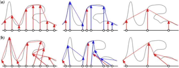
A more fundamental issue of hardware tessellation is that patches are uniformly subdivided according to a predefined pattern. This is especially problematic with standard scalar displacement along vertex normals (Figure2(a)). For a single level, vectorial dis-placement can mitigate this issue because vertices can be moved to (almost) arbitrary locations, which is essential to faithfully repro-duce features and folds (Figure2(b)). However, once the vectorial displacements have been computed for the finest level, vertices can-not be spatially redistributed to construct the coarser ones since the subdivision mechanism is fixed and uniform. Conversely, if start-ing from the coarser level, it is not possible to control topologically where new vertices will be added. This severely limits the ability to construct feature-aware LOD.
In addressing these problems, this paper makes two main contri-butions. First, we introduce a novel interpolation scheme between tessellation levels that enabled controllable custom fractional tes-sellation while avoiding swimming artifacts. It allows to finely con-trol the location of the topological changes between levels, paving the way for non-uniform tessellation (Section3). To support seam-less transitions across patches of different levels, we also designed a custom stitching mechanism. Our method only requires the stor-age of an additional index per vertex to link vertices form coarse to fine levels. Following Schäfer et al. [SPM⇤13], these indices and
displacements are stored as vertex attributes in a compact 1D ar-ray providing the necessary bijective mapping between the gener-ated vertices and their attributes, while saving graphics memory and avoiding cracks at texture atlas boundaries.
To exploit the flexibility introduced by our representation, our second contribution is a feature-preserving mesh simplification al-gorithm. Starting from a base mesh tessellated and displaced at the
Figure 1: Fractional tessellation patterns at factors 6, 4.9 and 4. Colored lines highlight the three strips which are collapsed/split during the transition.
Figure 2: Schematic comparison of scalar (a) and vectorial (b) dis-placement mapping for the same geometry (gray curve) at two suc-cessive integer levels (in red) and a fractional level (in blue). Vec-torial displacement better represents the input signal, and enables folds. Yet both approaches suffer from swimming artifacts when the pattern continuously changes with fractional tessellation (middle column); the surface appears to fluctuate due to the undersampling of the displacement map.
finest level, our algorithm progressively decimates the mesh while matching the hardware tessellation pattern at successive levels. In-deed, even though we are able to control the location of topological changes between levels, the mesh connectivity of each level still has to match the tessellation pattern. This introduces hard and dif-ficult constraints on the generation of the levels. In particular, we show that among all the topological simplification possibilities, a large number of them can be explored by extending the notion of edge-collapse to the contraction of entire and consistent strips of edges. Optimizing these strips according to some geometric error metric, we devise a very efficient, yet simple simplification algo-rithm as detailed in Section4.
2. Related work
We first provide a brief introduction on modern GPU tessella-tion (for a comprehensive survey of past and present techniques see [SKU08,NKF⇤15]), and then discuss recent methods that
ap-ply displacement mapping in this context. 2.1. Background on hardware tessellation
Hardware tessellation is based on a uniform subdivision pattern of input triangular or quadrangular patches [Mor01]. Each patch can be tessellated at a different tessellation factor, and independent fac-tors can be chosen for patch boundaries. Yet a common factor needs
to be assigned to shared boundaries to obtain a watertight adaptive tessellation. With the integer tessellation scheme, this factor defines the number of segments of a tessellated boundary. Current GPUs support any integer factor in the [1,64] range.
To enable continuous LOD transitions, Moreton [Mor01] also presents an even and odd fractional tessellation scheme: factors are defined on a continuous scale and match integer tessellation for even or odd numbers respectively. For instance, as depicted in Figure1, a smooth transition from a coarse to a fine even factor is achieved by splitting one strip in each parametric direction and smoothly sliding the vertices until they reach their next integer po-sition. Conversely, a transition from a fine to a coarse integer factor is accomplished by gradually collapsing pairs of vertices. This frac-tional tessellation scheme is very effective at removing popping ar-tifact when adaptively evaluating subdivision surface [NLMD12].
2.2. Displacement mapping with GPU tessellation
As discussed in many previous work [NKF⇤15], fractional
tessel-lation introduces swimming artifacts when displacement mapping is applied. The generated vertices are progressively sliding in para-metric space. Consequently they sample the displacement map at different locations in time, which produces undulations of the final surface as depicted in Figure2.
Nießner et al. [NL13] address this issue by representing the dis-placements as a scalar-valued biquadratic B-spline surface over a Catmull-Clark subdivision surface. Such analytic displacements re-duce swimming artifacts by avoiding undersampling of the dis-placement map, as well as texture seams and normal recomputa-tion. However this approach is restricted to subdivision surfaces and scalar displacements; it cannot represent sharp edges, and LOD transitions are limited to simple mip-mapping which cannot com-pletely avoid swimming as explained by Schäfer et al. [SPM⇤13].
As mentioned in the introduction, a more radical approach con-sists in disabling fractional tessellation and implementing some kind of tri-linear interpolation of the displacements across the lev-els [SPM⇤13]. However, this strategy is limited to uniform
subdi-vision scheme and power-of-two levels.
To improve on the uniformity of hardware tessellation, Liktor et al. [LPD14] present a GPU Reyes-style subdivision technique that gradually generates fractional sub-patches according to some LOD metric. Those sub-patches can then be diced using regular fractional hardware tessellation, thus allowing continuous adaptive tessellation beyond GPU limits.
Jang and Han [JH12,JH13] propose two methods to gen-erate feature-aware vector displacement maps. The first one reparametrizes the detailed mesh to take into account sharp fea-tures during sampling. The second method achieves curvature-based sampling using an indirect scalar displacement map. In both cases the gain is limited to the finest level of tessellation; subse-quent levels are sampled with the fixed uniform tessellation pattern.
T. Lambert, P. Bénard, G. Guennebaud / Multi-Resolution Meshes for Feature-Aware Hardware Tessellation 3. Controllable fractional tessellation
In this section, we present our flexible LOD blending scheme, which extends the GPU fractional tessellation in two ways. First, it avoids swimming artifacts by applying fractional interpolation on the displaced surface rather than in the parametric domain. Second, during the transition between two levels, any vertex of the fine level can be smoothly introduced from any nearby vertex of the coarse one. In contrast to standard fractional tessellation, this relationship needs to be explicitly stored, as described in Section3.1. Further-more, our approach completely by-passes both the fractional and adaptive tessellation mechanisms built in the GPU: it makes only use of integer tessellation with equal factors for patch interior and boundaries. Both mechanisms are reintroduced in a custom and controllable manner, as detailed in Section3.2and Section3.3 re-spectively.
For the sake of clarity, from now on we focus on triangular meshes, yet our entire framework can easily be extended to pro-cess quadrilateral patches, as discussed in Section6.
3.1. Representation and storage
Our approach is based on a hierarchical representation of the LODs that is stored using Schäfer et al.’s linear indexing [SPM⇤13]. The
key idea of this method is to pre-compute and store directly with the mesh the vertex attributes (colors, normals, displacements) for all vertices generated by the tessellation. Compared to texture stor-age, cracks are avoided and memory can be saved since optimal sampling rate can be adaptively specified on a per triangle basis. Yet, to fetch these attributes during the rendering step, a unique in-dex is required to identify each vertex. Current GPUs do not expose such an index, Schäfer et al. showed that it can be inferred from the patch index and the fractional barycentric coordinates of the gen-erated vertices. Within a given patch of index ipat a level l, each
generated vertex is identified by a unique index iv2 [0,N(l)[, where N(l) is the number of vertices per patch at level l. Any vertex of the whole tessellated mesh can thus be uniquely identified through the triplet (l,ip,iv).
In our work, this indexing serves two purposes. First, it permits to precisely assign any attribute (e.g., the displacement vectors) to the generated vertices by compactly storing them into a global 1D array. In our implementation, this linearization follows the lexico-graphic order of the triplet.
Second, this index is used to establish the relationship between vertices of adjacent levels, as needed to customize fractional tes-sellation. Namely, each vertex V = (l + 1,ip,iv)is associated to a parent vertex V0= (l,ip,i0
v)of the coarser level by storing its index
i0vas an additional attribute, that we call the blending index. This
leads to a hierarchical representation of the LOD depicted in Fig-ure3defining how vertices should be interpolated during a tran-sition from level l to the next level l + 1, as detailed in the next subsection.
3.2. Continuous LOD
Our hierarchical representation is directly amenable for fractional-like tessellation. For the sake of simplicity, let us consider a single
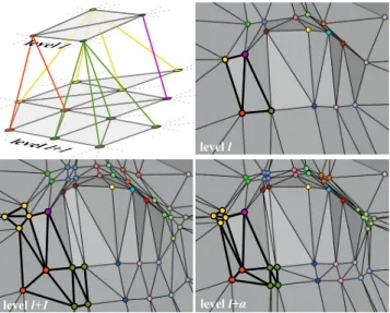
level l
level l+α level l+1
Figure 3: Transition between two successive levels l and l + 1. At the intermediate level l +a, the vertex positions are obtained by linear interpolation between their parent positions at level l and their final positions at level l + 1. The top-left figure depicts the respective hierarchical representation for the thicker subset of tri-angles.
patch. To interpolate between two subsequent levels l and l + 1 at a fractiona 2]0,1], the idea is to smoothly move each vertex of level l + 1 towards its parent vertex of the coarser level l asa vanishes. This behavior is depicted in Figure3. More precisely, a patch at a fractional level l +a is first instantiated at the factor of the level l + 1 through integer hardware tessellation. Then, for each gener-ated vertex, its own and parent attributes are fetched and linearly interpolated according to the parametera. However, in order to avoid swimming artifacts, we do not directly interpolate displace-ment attributes. Instead, we interpolate the object space positions piandpi0of the current vertex i and parent vertex i0respectively.
Unlikepiwhich is easily computed,pi0 is more challenging to
obtain as we do not have direct access to its barycentric coordinates. Recovering them from the blending index i0would involve
numer-ous prohibitive integer divisions and modulo. Thus, since the tes-sellation patterns are fixed, we propose to simply precompute and store them once and for all, at every needed tessellation factor. This array requires only 4291 entries in total for power-of-two factors, which is very lightweight and does not impact performance.
This representation and blending scheme are very versatile but, since the tessellation pattern of each level is fixed, the hierarchy de-fined by the blending indices must satisfy some constraints. First, whena vanishes, the degenerated pattern of the higher level l + 1 must exactly match the pattern of the coarser level l. This hard con-straint forces the intermediate levels to match even or odd tessel-lation factors. In practice storing the displacement attributes for all even or odd factors would be too expensive anyway, and we thus store and interpolate between power-of-two levels only. (For the sake of clarity, some of the illustrations of this paper have been made using even-levels though.) To prevent dependencies across adjacent patches, we also forbid vertices of a given patch to be
[6]3.8 [6] [6]3.8 [6] [4]3.8 [6] [6]4.2 [6] [4] [6] [6] [6]
Figure 4: Transition of a patch-border from factor 6 to 4 while the interior factor remains constant at 6.(a) The hardware tes-sellator wants to contract the orange strip to obtained the pattern in(b). Our simplification algorithm decided to collapse the purple strip, which implies the blending depicted in(c) with blue arrows. This works as long as the integer boundary factor is 6, but once it changes to 4, the blue edges are flipped to produce the red ones (d). To solve this problem, we set the integer boundary factor at the patch factor (i.e., 6 instead of 4);(e) we conceptually put bound-ary vertices at their parent position to reach factor 4 (blue arrows), and(f) we apply our blending mechanism with the grand-parent to achieve 3.8 fractional tessellation (green arrows).
paired with vertices of a different one, which explains why stor-ing the in-patch vertex index i0
vas blending index is sufficient. As
a consequence, vertices generated along patch-borders can only be parented with analogous vertices. Finally, to prevent swimming ar-tifacts during morphing, vertices should be paired to geometrically close ones. All these constraints have to be considered during the LOD generation as described in Section4.
3.3. Adaptive LOD
For each patch, tessellation factors are first defined for its borders using some metric (see Section5.1for details), and then its inte-rior factor is set to the maximum of those. Adjacent patches can be tessellated at different resolutions, so we need to define how they can be seamlessly connected. A naive approach would be to assign a common tessellation factor to the shared patch-borders, and let the hardware tessellator connects the interior vertices and boundary vertices for us. As illustrated in Figure4(a-d), since we do not nec-essarily pair boundary vertices in the same way the tessellator does, edges connecting the interior with the boundary can suddenly flip. This not only introduces popping artifacts, but more importantly it creates invalid geometry in saddle-like area as shown in Figure5.
Our solution still defines a common fractional factor for the shared patch-borders, but we accomplish the stitching manually using our hierarchical representation as illustrated in Figure4 (e-f). Patch boundaries are subdivided at the same rate than the patch interior, thus completely bypassing the hardware adaptive tessella-tion. Let us assume that the current patch boundary is subdivided at level l + 1, and that the target fractional level for the boundary
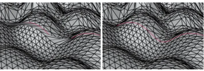
Figure 5: Adaptive LOD along patch-borders. Left: with our LOD representation, the hardware adaptive tessellation produces invalid geometry along patch boundaries (in red) whose level differs from the interior level.Right: our manual stitching technique solves this problem with a negligible overhead.
is l 1 +b. To reach this fractional level, we apply the blending scheme presented in the previous section between the parent and grand-parent of each boundary vertex. This mechanism can be ap-plied recursively to handle resolution differences of more than one levels, even though this is very unlikely to happen especially when using power-of-two levels.
Interior vertices may have ancestors that lie on a patch bound-ary, hence having a different tessellation factor. Let us assume that the fractional levels of the patch interior and border are l +a, and l 1 +b respectively. If b > 1 then the actual integer subdi-vision levels for both the interior and border are the same. Such a vertex will be positioned at a ratio a between its initial po-sition pi and its parent position pi0, which is the desired
be-havior. However, as soon as b becomes smaller than one, the previous mechanism will suddenly put this vertex on the patch-border at a position pb corresponding to the ratio b between its two subsequent ancestors (pi0 and pi00 in the figure below).
p
ip
i 'p
i ' ' 1−βp
β βα
1−α
Instead, to avoid popping artifacts, such a vertex must be progressively moved towards the patch border. This is eas-ily accomplished by computing its ac-tual position as the ratioa between its
initial positionpiand target positionpb(leading to red point).
4. Strip-based mesh simplification
In this section we present our feature-aware simplification algo-rithm that computes the final position of the vertices at every level, and the blending indices required to smoothly transition between those. Our general objective is to distribute the vertices of each level to best represent the most significant features of the input geome-try. Whereas this is a well studied topic in the literature [BKP⇤10],
our context implies two specific problems. First, at each level, the simplified geometry must coincide with the predefined tessellation pattern. Second, as seen in Section3.2, we need to find a continuous mapping between two subsequent levels which guarantees that the collapsed topology of the mesh at level l + 1 matches the topology at level l when the transition starts.
The first problem could be addressed by applying surface fit-ting methods [KVL99,YLSL11,NYL14] on each level. How-ever, finding a consistent match between the levels as requested by the second criterion would then be extremely difficult, and
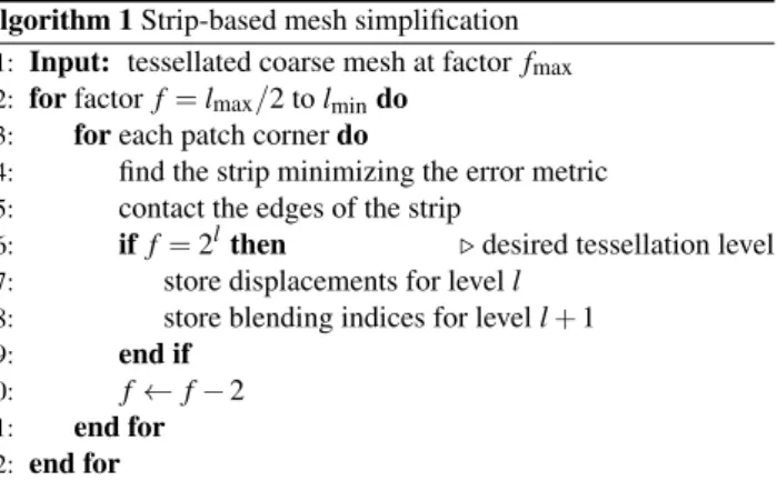
T. Lambert, P. Bénard, G. Guennebaud / Multi-Resolution Meshes for Feature-Aware Hardware Tessellation Algorithm 1 Strip-based mesh simplification
1: Input: tessellated coarse mesh at factor fmax
2: for factor f = lmax/2 to lmindo
3: for each patch corner do
4: find the strip minimizing the error metric
5: contact the edges of the strip
6: if f = 2lthen .desired tessellation level
7: store displacements for level l
8: store blending indices for level l + 1
9: end if
10: f f 2
11: end for
12: end for
even impossible without adding explicit dependencies between the levels during their optimization. In contrast, this second prob-lem is naturally overcome using iterative mesh decimation algo-rithms [Hop96,GH97,LT98] as the matching can be directly estab-lished during edge-collapse. But then, it becomes extremely diffi-cult to make the decimation process converge to a predefined mesh connectivity.
Actually, for both approaches, the core of the problem can be re-duced into the problem of deciding whether a given graph is a mi-nor of another, which is NP-complete. If the given graph is fixed, it can be solved in polynomial time [KKR12], yet with a constant that depends super-exponentially on the size of the graph. This is intractable in the general case, but we are not dealing with arbitrary graphs and we know at least one solution: the default transition of the hardware tessellation engine (Figure1). We show in the follow-ing how to construct many others.
We also argue that both problems need to be solved at the same time, and we extend edge-collapse decimation algorithms to a strip-based flavor which produces at every step a mesh compatible with hardware tessellation.
4.1. Algorithm overview
Our simplification procedure is sketched in Algorithm1. We as-sume as input a mesh defined as a set of triangular patches tes-sellated at the maximum even factor fmax and matching the
hard-ware tessellation pattern. Then, the next even factor f = fmax 2
is constructed by collapsing a set of adequate strips of edges that minimizes a given geometric error. We properly defines the set of feasible contractions in Section4.2, and we show how to quickly explore it to find the best contractions in Section4.3. If the current factor f corresponds to a desired power-of-two level l (i.e., f = 2l), then the displacements for the current level l are stored as well as the blending indices for the child level l + 1. The ring-based sim-plification is repeated until the coarser level lminis reached.
4.2. Feasible contractions
For triangular patches, the default transition of the tessellation en-gine consists in collapsing three “straight” strips as shown in Fig-ure 1. We extend this notion of strip to give more flexibility to the transitions. To effectively pass from the tessellation factor f to
Figure 6: (a) A strip (in green) is a continuous list of edges join-ing two “opposite” half-patch-borders (thick purple and orange lines).(b) Unfolding the patch into a uniform grid, a strip can be seen as a path in the DAG constructed over the patch edges.(c) This implicit graph can be easily traversed walking on a half-edge data structure.(d) Strips extend to x-strips when they crosses mul-tiple patches since they have to be connected on patch boundaries. Closed x-strips form rings (in red).
f 2, we first observe that 3 f edges need to be collapsed, including two edge-collapses per patch boundary. To preserve the regularity of the pattern, pairs of collapsed boundary edges have to be con-nected through strips of collapsed edges, with one strip per patch boundary. To make the definition of such strips tractable, we re-strict them to have equal length and to connect a pair of “opposite” half patch boundaries. In other words, each patch boundary is asso-ciated to one strip of f + 1 graph nodes connecting half-parts of its two adjacent patch boundaries. An example is given in Figure6(a). For a given boundary, its set of possible associated strips is easily defined after a reparametrization of the triangle such that its ver-tices lie on a uniform grid with the boundary and half-boundaries aligned on the vertical and horizontal axes respectively, as depicted in Figure6(b). Since the length of a strip is fixed, the only possibil-ity is to perform one edge-collapse per horizontal direction. Each horizontal edge being connected by two adjacent triangles, this op-eration produces a continuous strip, with the additional requirement that collapsed edges form a continuous strip.
The set of possible strips going from one half-boundary to the opposite one are best defined as a directed acyclic graph (DAG) whose nodes are the edges of the mesh. In this dual representa-tion, one strip corresponds to one path from a half-boundary to another. In practice, this graph does not have to be explicitly con-structed. As illustrated in Figure6(c), using an half-edge data struc-ture, a given node h has at most two children that are reached using the following operator compositions: op(next(op(prev(h)))) and op(prev(op(next(h)))). If the intermediate edge reached by prev(h) or next(h) is a patch-border, then the respective child does not exist.
4.3. Strip collapse
Our LOD simplification algorithm consists in finding the strips that minimize some feature-preserving error metric. We define the error of a strip as the sum of the error of each edge-collapse for which we use the classic Quadric Error Metric [GH97] for simplicity, but any alternative metric could be chosen.
Usually the coarse mesh is composed of several adjacent patches and we need to ensure the coherence between them. As illustrated in Figure6(d), strips ending along the same half-patch-border must be connected, or cracks will appear. This creates extended-strips (x-strips) that must be considered as a whole during the error min-imization. Each x-strip can be associated to a unique vertex of the coarse mesh, and vice versa. Its length is then proportional to the valence of the coarse mesh vertex. If the vertex does not lie on an open boundary, then the x-strip forms a closed ring (e.g., the red line in Figure6(d)).
Using the aforementioned dual representation of the feasible strips, finding the best x-strip associated to a given vertex of the coarse mesh boils down to a shortest path search. For a closed x-strip, the ending node must coincide with the starting node. In this case, we pick one arbitrary patch boundary and run a shortest path algorithm for each of the f /2 possible starting/ending nodes lying on the corresponding half-patch-border. Since we are dealing with a directed acyclic graph, each search is efficiently accomplished us-ing a variant of Dijkstra algorithm with linear complexity [CLR90]. For an open x-strip, both starting and ending nodes can be freely chosen. This case can be solved in a single pass by connecting all starting and ending nodes to two virtual nodes, and computing the shortest path between those using the same Dijkstra variant.
Once an optimal x-strip has been found, each of its edges is col-lapsed to a single vertex positioned at the minimum of the error metric. Contrary to Garland and Heckbert [GH97], we force the op-timal position to be on the edge under contraction. It allows linear interpolation of the attributes, which reduces distortions of texture coordinates, and avoids artifacts at texture atlas seems. In addition, this constraint prevents triangle flips or folds that cannot be solved as a post-process by edge-flip due to the fixed tessellation pattern.
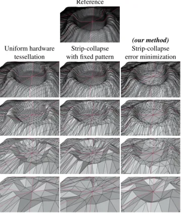
In Figure7we compare our approach with regular uniform hard-ware tessellation and a variant of our strip-based decimation algo-rithm which is constrained to choose the straight strips of the tes-sellation pattern. At every level, our approach better represents the features of the input geometry by simplifying flat areas while pre-serving regions of higher curvature, such as the top of the “crater”. There are fundamental differences between our strip-based sim-plification algorithm and classical edge-collapse decimation. The later contracts one edge after the other, selecting the one with the largest error every time. After each collapse, the error of surround-ing edges must be recomputed, and a partially sorted list of edges must be updated. In our case, edges defining a strip have no shared vertices: edges can thus be collapsed in an arbitrary order, and the errors do not have to be recomputed while searching for the optimal x-strip. The error of surrounding edges only needs to be updated af-ter a full x-strip has been contracted. Furthermore, the three strips of a patch travel in a different direction of contraction, and each strip crosses the two others only once. Consequently the influence
Reference
(our method)
Uniform hardware Strip-collapse Strip-collapse
tessellation with fixed pattern error minimization
Figure 7: Starting from the same 8 patches and displacement map, comparison of the LOD representation generated by three approaches for the factors 32, 16, 8 and 4 (from top to bottom). Left: Uniform hardware tessellation. Middle: Mesh decimation constrained to choose the same strips as the tessellation pattern. Right: Our method, i.e., mesh decimation collapsing the strips that minimize an error metric. For each level, our approach better pre-serves the input geometry by spatially redistributing the polygonal size and density.
between strips is marginal, and the order in which strips are se-lected and collapsed has a minor impact on the final result. In our implementation, x-strips are thus processed in an arbitrary order. 5. Implementation and Results
5.1. Implementation details
Our rendering pipeline follows as closely as possible the standard hardware tessellation steps. The tessellation factors are computed using the heuristic employed by Schäfer et al. [SPM⇤13]. During
a preprocessing step, we compute and store for each patch at each level its Hausdorff distance to the input detailed mesh. Then, when rendering the mesh, the patch-border tessellation factors are cho-sen such that the screen-space Hausdorff distance in pixel matches a user define target. The interior tessellation factor is then defined as the maximum of those. To enable deformations of the base mesh, we store the displacement vectors in tangent space. Patch corners are animated in the vertex shader and their local tangent frames are interpolated after tessellation to compute final world space posi-tions. The shading is computed per-fragment using an anti-aliased
T. Lambert, P. Bénard, G. Guennebaud / Multi-Resolution Meshes for Feature-Aware Hardware Tessellation
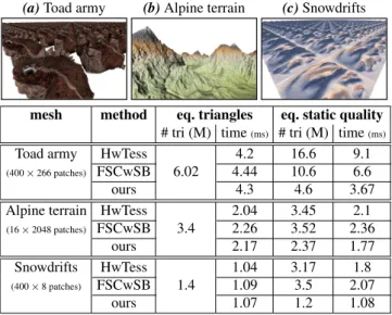
(a) Toad army (b) Alpine terrain (c) Snowdrifts
mesh method eq. triangles eq. static quality
# tri (M) time(ms) # tri (M) time(ms)
Toad army HwTess
6.02
4.2 16.6 9.1
(400 ⇥ 266 patches) FSCwSB 4.44 10.6 6.6
ours 4.3 4.6 3.67
Alpine terrain HwTess
3.4 2.04 3.45 2.1 (16 ⇥ 2048 patches) FSCwSB 2.26 3.52 2.36 ours 2.17 2.37 1.77 Snowdrifts HwTess 1.4 1.04 3.17 1.8 (400 ⇥ 8 patches) FSCwSB 1.09 3.5 2.07 ours 1.07 1.2 1.08
Table 1: Performance comparison of our method with uniform hardware tessellation (HwTess), and FSCwSB method standing for Fixed Strip Collapse with Schäfer et al. [SPM⇤13] Blending
mech-anism. The three bench scenes are:(a) instancing of 400 “Toad” meshes,(b) instancing of 16 “Alpine terrain” (each being repre-sented as 32 by 32 patch grid), and(c), instancing of 400 “Snow-drifts” meshes. Comparisons are conducted for both equal num-ber of rendered triangles, and same visual quality on a static im-age. Performances recorded on a Intel i7-4790K @ 4.00GHz with a Nvidia Geforce 980 GTX; window resolution of 1920 ⇥ 1140 px. normal map [Tok04] and, optionally, a color texture. Since our sim-plification algorithm repositions all the vertices at each level, inter-polating texture coordinates from the patch corner would produce sliding artifacts. We avoid those by storing the UVs as additional vertex attributes which are pre-computed during edge-collapses, and interpolated across levels at rendering time.
5.2. Memory consumption and performances
Regardless of the LOD rendering technique, the 3D positions of the detailed mesh (i.e., at level 64) and of the intermediate LODs need to be stored. As motivated in [SPM⇤13], storing those into 2D
mip-mapped textures is not optimal due to empty regions in tex-ture atlases, and the need for oversampling to guarantee an accurate mapping. In contrast, storing them per vertex is memory optimal. The memory overhead of our approach comes from one integer in-dex per vertex for the blending, and two UV-coordinates to apply textures. In our prototype implementation, each scalar attribute is simply stored as a 32 bits float or integer value, leading to a total of 24 Bytes per vertex. Neglecting per-patch attributes, this implies a cost of about 36⇥N bytes to store the N vertices of the detailed and intermediate power-of-two levels. Our approach thus remains very memory efficient since simply storing the detailed textured mesh as a traditional indexed-triangle-list without LOD would already re-quires 44 ⇥ N bytes, and previous progressive LOD rendering sys-tems based on vertex-splits require at least 69 ⇥ N bytes [LSH10]. Moreover, in a production implementation, these numbers can be greatly reduced as discussed in Section6. Overall, the Toad and
Alpine terrain models shown in Table1require 28MB and 211MB respectively to store all power-of-two LODs up to factor 64, the maximum tessellation factor supported by current GPUs.
Table1compares the performance of our approach to both stan-dard displacement mapping (denoted HwTess) and to an optimized variant of Schäfer et al. [SPM⇤13] trilinear interpolation scheme,
denoted FSCwSB. In this variant, we use our strip collapse LOD construction restricted to the fixed tessellation pattern (as in Fig-ure7, middle), and we optimize the LOD blending stage by ob-serving that when using power-of-two levels (as required for dis-placement maps), the bilinear blend performed within the coarse level is equivalent to a single linear blend along an edge, hence reducing the number of memory fetches from five to three. When targeting the same number of rendered triangles (Table1, middle columns), our custom blending exhibits a marginal overhead com-pared to HwTess, while being slightly more lightweight than the optimized FSCwSB variant because, for most vertices, our method only needs to perform two memory fetches instead of three. When targeting approximately the same visual quality on a static image (Table1, right columns), our approach considerably reduces the number of generated triangles, producing up to a ⇥2 speed-up.
We emphasize that in such comparisons, unlike our method and FSCwSB, the HwTess method will still exhibit temporal artifacts as seen in the accompanying video. This table also reveals that even though each level of the FSCwSB variant exhibits a lower error than HwTess, this gain is not always enough to compensate for the more gradual transition levels of even-fractional-tessellation. This explains why FSCwSB generates sometimes more triangles than HwTess for the same static image quality, whereas our ap-proach constantly produces fewer triangles even for the Alpine ter-rain model which exhibits large flat areas.
5.3. Qualitative comparisons
The quality of our generated LODs and its superiority to both stan-dard displacement maps and strip-collapse algorithm constrained to follow the fixed tessellation patterns have already been demon-strated in Figure7. Even though the later variant slightly improves upon displacement maps by repositioning the vertices of the coarser level according to the quadratic error metric, this figure shows that most of the gains of our approach actually come from its non-uniformity in choosing optimal strips. Figure8shows a more com-plicated example with folds and sharp edges. Even at the factor 32, standard tessellation introduces strong oscillations in the concave region of the drifts. Those become prominently visible at factor 16, even with a normal-map-based shading. At level 16, sharp fea-tures are already significantly degraded by the uniform sampling of the displacement map, whereas our approach manages to properly align triangle edges with sharp features. As a result, our approach remains very close to the reference image, even at a factor 8 for which 98.5% of the vertices have been removed.
Figure9further shows that these well-represented features re-main very stable during the continuous transition between LODs. It also illustrates that, when transitioning between two subsequent levels with power-of-two tessellation, we obtain a very different behavior than standard fractional tessellation as many more strips split or collapse simultaneously.
Our method Uniform hw. tess.
Level 32 Level 16 Level 8
Figure 8: Comparison on the “Snowdrifts” test scene (8 patches). Uniform hardware tessellation (top) fails at representing accurately sharp features and areas of high curvature, such as the top and deep part of the drifts, which produces tessellation artifacts. Our method(bottom) better preserves those regions by adapting the triangle size and aligning their edges with those features.
Figure 9: Zoom-out sequence generated by our controllable fractional tessellation. Observe how the sharp features are well preserved during the continuous simplification. The bottom patch transitions from integer factors 32 to 16, whereas the top patch stays at an integer factor 16 but nearly approaches the next power-of-two factor 8 at the last frame.
Figures 10 and 11 provide comparisons on larger scale mod-els with view-dependent continuous and adaptive LOD enabled. In both cases, triangle edges are better aligned with features thus avoiding distorted sharp edges and shading artifacts produced by invalid geometry.
The stability of our continuous blending is demonstrated in the accompanying video, which shows progressive zooms and flight-overs for the different scenes used in this paper. In particular, it can be seen that swimming artifacts are fully avoided by our fractional tessellation mechanism.
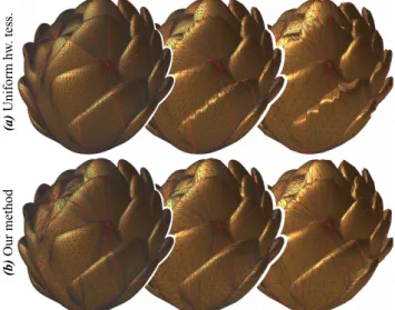
Finally, Figure12compares the LODs produced on a difficult model exhibiting extreme folds. Our method still outperforms uni-form tessellation; our levels 16 and 8 have similar quality than uniform levels 32 and 16 respectively. Yet we can observe that our generated triangulation is not fully optimal in certain loca-tions. This is partly explained by the use of a uniform sampling for generating the finest level. This helped us to make fair com-parisons to other methods, but we believe that our method could generate more accurate LODs by starting from a better initial so-lution, for instance by adopting one of the existing surface fitting techniques [KVL99,YLSL11,NYL14]. Better LODs could also be
achieved by adopting a more sophisticated heuristic to reposition the vertices, for instance, by applying relaxation steps as in the aforementioned fitting methods.
6. Discussions and extensions
Quad tessellation Our framework can easily handle quadrilateral patches, provided that quad interiors are tessellated at the same level in each direction. The computation of indexes as described in Section3.1can be considerably simplified since the generated vertices lie on a regular lattice. The main difference concerns the x-strips as defined in Section4.3: they are usually much longer and can even exhibit some self-intersections. This has no impact neither on our algorithm nor on its performance because finding an optimal x-strip is linear with respect to its length. Only Algorithm1must be slightly modified. Instead of processing the x-strips on a per patch corner basis, we pick a half-boundary that has not been reduced yet and find the optimal x-strip passing through it; we iterate until all half-boundaries have been reduced.
On quad meshes, x-strips are very similar to the poly-chord structure of Daniels et al. [DSSC08], yet with a fundamental dif-ference: a given edge yields a unique poly-chord loop whereas, in our case, we deal with a binary graph with bounded width.
T. Lambert, P. Bénard, G. Guennebaud / Multi-Resolution Meshes for Feature-Aware Hardware Tessellation
Figure 10: Left: Image crops and Right: close-up views (same tes-sellation but different viewpoint) on the “Toad army” of Table1(a). Uniform hardware tessellation(top) degrades or misses major ge-ometric features of the displacement map, such as the shoulder crest and the sculpted stump, whereas our LOD mechanism (bot-tom) represents and simplifies them faithfully.
Feasible contractions In order to make the set of feasible con-tractions easily tractable, we made a few restrictions in Section4.2. As a result, our algorithm ignores a few possible contractions that could potentially lead to even more accurate LODs.
Compressed storage Our storage requirement could be signif-icantly reduced in two ways. First, the blending indices can be stored as 12 bits integers for tessellation factors up to 64 (which is the limit of current GPUs), and the texture coordinates could be heavily compressed by expressing them relatively to the inter-polated patch UVs, for instance using 16 bits fixed-point precision scalars. Likewise, displacement vectors could likely be compressed the same way without impact on the visual quality. Second, by us-ing a more advanced view-dependent error metric, one could limit the maximum tessellation factor on a per patch basis, similarly to the work of Schäfer et al. [SPM⇤13], thus saving the finer level
storage for patches of lower geometric complexity.
Animation Vector displacement mapping may produce artifacts (e.g., self-intersections, folds) after animation of the base mesh. Since our method tends to create large displacements when repo-sitioning vertices during simplification, it suffers from the same limitation. It could be alleviated using the indirect scalar mapping technique of Jang and Han [JH13], but converting arbitrary vector displacements into this representation is a not trivial.
Static meshes We presented and evaluated our method in the gen-eral context of an animated coarse mesh. However, if the
deforma-Figure 11: Left & Middle: Image crops and Right: close-up views on the “Alpine terrain” of Table 1(b). As highlighted in red, uniform hardware tessellation(a) suffers from sampling artifacts along the discontinuities of the displacement map. Our method(b) significantly improves their depiction by increasing the polygonal density in these areas and aligning edges of the tessellation with those features. (b ) O ur m et ho d (a ) U ni fo rm h w . t es s.
Figure 12: Level of details generated by uniform tessellation (a) and our method(b) on a difficult model with extreme folds. From left to right, factors 32, 16, and 8.
tion is applied to the tessellated mesh, or if the mesh is static, then instead of storing displacement vectors in tangent space, a faster approach consists in directly storing the final object space posi-tions. This not only saves some computation when applying the displacement vectors, but also avoids the need to store or recover the barycentric coordinates of the ancestors (Section3.2). Power-of-two levels Similarly to Schäfer et al.’s method [SPM⇤13] for swimming-free displacement mapping, the main
limitation of our approach is its practical restriction to power-of-two levels. Even though our approach can handle a finer
granular-ity up to even-levels, the memory required to store all the levels becomes prohibitively expensive. For power-of-two levels, the re-quired memory is approximatively doubled compared to the origi-nal mesh, whereas it is squared in the case of even-levels. We argue that this limitation is largely compensated by LODs of much higher geometric quality allowing to use lower tessellation factors for the same visual quality.
In addition, the transition between two even-factor levels is very unlikely to reduce the visual error unless all the vertices are slightly redistributed. Yet, in this case, temporal artifacts will be reintro-duced since all vertices will constantly and very rapidly move back and forth. On the other hand, we agree that even-factor levels are very useful when over-tessellating the mesh such that the projected tessellated triangles are below one pixel: swimming artifacts are effectively avoided, but at a prohibitive rendering cost.
7. Conclusions
We proposed a general framework for the construction and ren-dering of non-uniform LODs suitable for hardware tessellation. Its key component is a novel hierarchical representation of multi-resolution meshes that allows us to finely control the topological locations of vertex splits and merges. We thus managed to relax the regularity of fractional tessellation, while retaining the effi-ciency of the respective GPU’s units. Within our framework, we presented a dedicated mesh decimation scheme that can be driven by any edge-based error metric. In particular, by applying it with a feature-preserving geometric error, we leveraged for the first time hardware tessellation for feature-aware LOD rendering of meshes. Our framework opens the door to many opportunities for improve-ment, and could benefit from more specific and advanced metrics for decimation and LOD selection.
Acknowledgments
We would like to thank the anonymous reviewers for their com-ments and advice. This work has been supported by the ANR RichShape project (ANR-14-CE24-0004). The initial Toad model was created by Craig Barr. The Alpine terrain is based on the height-field provided bywww.virtual-lands-3d.com.
References
[BKP⇤10] BOTSCHM., KOBBELTL., PAULYM., ALLIEZP., LÉVYB.: Polygon Mesh Processing. A K Peters/CRC Press, 2010.4
[CLR90] CORMENT., LEISERSONC., , RIVEST R.: Introduction to Algorithms. McGraw-Hill, 1990.6
[DSSC08] DANIELSJ., SILVAC. T., SHEPHERDJ., COHENE.: Quadri-lateral mesh simplification. ACM Transactions on Graphics (2008), 148:1–148:9.8
[EAV99] EL-SANAJ., AZANLIE., VARSHNEYA.: Skip strips: Main-taining triangle strips for view-dependent rendering. In Proceedings of IEEE Visualization ’99 (1999), pp. 131–138.1
[GH97] GARLANDM., HECKBERTP. S.: Surface simplification using quadric error metrics. In Proceedings of ACM SIGGRAPH ’97 (1997), pp. 209–216.5,6
[Hop96] HOPPEH.: Progressive meshes. In Proceedings of ACM SIG-GRAPH ’96 (1996), pp. 99–108.5
[Hop97] HOPPEH.: View-dependent refinement of progressive meshes. In Proceedings of ACM SIGGRAPH ’97 (1997), pp. 189–198.1 [JH12] JANGH., HAN J.: Feature-Preserving Displacement Mapping
With Graphics Processing Unit (GPU) Tessellation. Computer Graphics Forum 31, 6 (2012), 1880–1894.2
[JH13] JANGH., HANJ.: GPU-optimized indirect scalar displacement mapping. In CAD Computer Aided Design (2013), vol. 45, pp. 517–522. 2,9
[KKR12] KAWARABAYASHIK.-I., KOBAYASHIY., REEDB.: The dis-joint paths problem in quadratic time. Journal of Combinatorial Theory, Series B 102, 2 (2012), 424–435.5
[KVL99] KOBBELTL. P., VORSATZJ., LABSIKU.A.: A shrink wrap-ping approach to remeshing polygonal surfaces. Computer Graphics Forum 18, 3 (1999), 119–130.4,8
[LPD14] LIKTORG., PANM., DACHSBACHERC.: Fractional Reyes-Style Adaptive Tessellation for Continuous Level of Detail. Computer Graphics Forum 33, 7 (2014), 191–198.2
[LSH10] LIANG HU, SANDER P. V., HOPPE H.: Parallel View-Dependent Level-of-Detail Control. IEEE Transactions on Visualization and Computer Graphics 16, 5 (2010), 718–728.1,7
[LT98] LINDSTROMP., TURKG.: Fast and memory efficient polygo-nal simplification. In Proceedings of IEEE Visualization ’98 (1998), pp. 279–286.5
[LWC⇤02] LUEBKE D., WATSON B., COHEN J. D., REDDY M., VARSHNEYA.: Level of Detail for 3D Graphics. Elsevier Science Inc., 2002.1
[Mor01] MORETONH.: Watertight tessellation using forward differenc-ing. In Proceedings of Graphics Hardware (2001), pp. 25–32.1,2 [NKF⇤15] NIESSNERM., KEINERTB., FISHERM., STAMMINGERM.,
LOOPC., SCHÄFERH.: Real-time rendering techniques with hardware tessellation. Computer Graphics Forum (2015).2
[NL13] NIESSNERM., LOOPC.: Analytic displacement mapping using hardware tessellation. ACM Transactions on Graphics 32, 3 (2013), 1–9. 2
[NLMD12] NIESSNERM., LOOPC., MEYERM., DEROSET.: Feature-adaptive GPU rendering of Catmull-Clark subdivision surfaces. ACM Transactions on Graphics 31, 1 (2012), 1–11.2
[NYL14] NIVOLIERSV., YAND.-M., LÉVYB.: Fitting polynomial sur-faces to triangular meshes with voronoi squared distance minimization. Engineering with Computers 30, 3 (2014), 289–300.4,8
[SKU08] SZIRMAY-KALOSL., UMENHOFFERT.: Displacement map-ping on the GPU state of the art. Computer Graphics Forum 27, 6 (2008), 1567–1592.2
[SP03] SHAFAEM., PAJAROLAR.: Dstrips: dynamic triangle strips for real-time mesh simplification and rendering. In Proceedings of the 11th Pacific Conference on Computer Graphics and Applications. (2003), pp. 271–280.1
[SPM⇤13] SCHÄFERH., PRUSM., MEYERQ., SUESSMUTHJ., STAM-MINGERM.: Multiresolution Attributes for Hardware Tessellated Ob-jects. IEEE Transactions on Visualization and Computer Graphics 19, 9 (2013), 1488–1498.1,2,3,6,7,9
[TBB09] TATARCHUKN., BARCZAKJ., BILODEAUB.: Programming for real-time tessellation on GPU. Tech. rep., AMD Inc., 2009.1 [Tok04] TOKSVIGM.: Mipmapping Normal Maps. Tech. rep., 2004.7 [YLSL11] YEHI.-C., LINC.-H., SORKINEO., LEET.-Y.:
Template-based 3d model fitting using dual-domain relaxation. IEEE Transactions on Visualization and Computer Graphics 17, 8 (2011), 1178–1190.4,8