READ THESE TERMS AND CONDITIONS CAREFULLY BEFORE USING THIS WEBSITE.
https://nrc-publications.canada.ca/eng/copyright
Vous avez des questions? Nous pouvons vous aider. Pour communiquer directement avec un auteur, consultez la
première page de la revue dans laquelle son article a été publié afin de trouver ses coordonnées. Si vous n’arrivez pas à les repérer, communiquez avec nous à PublicationsArchive-ArchivesPublications@nrc-cnrc.gc.ca.
Questions? Contact the NRC Publications Archive team at
PublicationsArchive-ArchivesPublications@nrc-cnrc.gc.ca. If you wish to email the authors directly, please see the first page of the publication for their contact information.
NRC Publications Archive
Archives des publications du CNRC
This publication could be one of several versions: author’s original, accepted manuscript or the publisher’s version. / La version de cette publication peut être l’une des suivantes : la version prépublication de l’auteur, la version acceptée du manuscrit ou la version de l’éditeur.
Access and use of this website and the material on it are subject to the Terms and Conditions set forth at
An Approach for the Validation of Fault-based Knowledge Through the Automated Generation of Model-based Functional Knowledge.
Abu-Hakima, Suhayya
https://publications-cnrc.canada.ca/fra/droits
L’accès à ce site Web et l’utilisation de son contenu sont assujettis aux conditions présentées dans le site
LISEZ CES CONDITIONS ATTENTIVEMENT AVANT D’UTILISER CE SITE WEB.
NRC Publications Record / Notice d'Archives des publications de CNRC:
https://nrc-publications.canada.ca/eng/view/object/?id=dd0f086f-1300-4b32-9b9f-014d8ae0c29c https://publications-cnrc.canada.ca/fra/voir/objet/?id=dd0f086f-1300-4b32-9b9f-014d8ae0c29c
Abstract
The paper addresses the problem of validation of fault knowledge through automated model acquisition. The Diagnostic Remodeler (DR) algorithm has been imple-mented for the automated generation of behavioural com-ponent models with an explicit representation of function by re-using fault-based knowledge. DR re-uses as its first application the fault knowledge of the Jet Engine Trouble-shooting Assistant (JETA). DR extracts a model of the Main Fuel System using real-world engine fault knowledge and two types of background knowledge as input: device depen-dent and device independepen-dent background knowledge. The generated model uncovers gaps and inconsistencies in the fault-based knowledge. To demonstrate DR’s generality, it was applied to coffee maker fault knowledge to extract the component models of a full coffee device. It is possible to use DR as a general means of validating fault knowledge.
1 Introduction
Artificial Intelligence (AI) researchers in the model-based diagnosis (MBD) community dis-miss fault-based diagnostic (FBD) systems far too easily [van Soest 93, Abu-Hanna 89]. Many MBD authors incorrectly assume that fault-based knowledge is still represented and organized as a flat file of if-then production rules as it was in the days of MYCIN [Clancey 86]. MYCIN was the earliest well-known fault-based diagnostic sys-tem and it was implemented in the 1970’s. Much work has evolved and improved on MYCIN’s main diagnostic themes. Today’s FBD systems recognize the need for developing systems that explicitly separate the control from the data in reasoning. This separation aids in tractable rea-soning and in searching for diagnoses in finite time [Chandrasekaran 86, Goel et al. 87]. This separation is also essential in justifying system behaviour and in generating good explanations [Abu-Hakima and Oppacher 90]. Currently
developed FBD systems address complex real-world problems, are highly structured, and thus, their knowledge bases are very efficiently searched. In essence, FBD systems can be vali-dated. Validation here is taken to imply that the knowledge-based system can generate predictable and accurate results which satisfy specification goals [Laurent 92].
Despite FBD strengths, MBD researchers repeat-edly criticize fault-based systems as limited, and inadequate for troubleshooting novel faults. What is often forgotten by the MBD supporters, are the number of implemented FBD systems that are in successful daily use, as exemplified in the litera-ture [Abu-Hakima 94b]. Furthermore, MBD has been shown to be computationally expensive and intractable for complex devices. MBD systems are additionally limited by the generation of models that accurately reflect the systems they model. If a model does not correctly propagate the behaviours of a device, it will not be able to adequately diag-nose the device, let alone discover novel faults. Thus MBD models are difficult to validate.
My work is intended to form a bridge between the FBD and MBD communities. Although the two communities are striving towards the same goal, mainly the efficient and accurate diagnosis of devices, they have not closely examined or taken advantage of their commonly shared problems. They share problems in knowledge acquisition for diagnosis, be it fault or model knowledge. The researchers in the two camps need to address com-mon approaches for structuring, reasoning about, explaining, validating and re-using knowledge.
An Approach for the Validation of Fault-Based Knowledge through the Automated
Generation of Model-Based Functional Knowledge
Suhayya Abu-Hakima
Seamless Personal Information Networking Group Institute for Information Technology National Research Council of Canada
Ottawa, Canada K1A 0R6 suhayya@ai.iit.nrc.ca tel: 613-991-1231 fax: 613-952-7151
One problem in bridging FBD and MBD, is the problem of relating, and possibly re-using device fault knowledge as model knowledge. To address this problem, the Diagnostic Remodeler (DR) algorithm, the subject of this paper, has been for-mulated, implemented, and tested [Abu-Hakima 94a; 93]. DR illustrates that well-structured fault knowledge can be mapped and re-used, as model knowledge. DR addresses the re-use of existing complex device fault knowledge in conjunction with background knowledge for the generation of black box component models of a device. These component models represent device structure, behaviour, and function and are typical of models used in model-based reasoning [Nayak and Struss 94; Abu-Hanna et al. 92]. DR thus maintains two views for the diagnostic knowledge of a single device or subsystem, a fault-based view, and a model-based one. These two views help illustrate that fault and model knowledge for the same device are related, and given one view, the second can be extracted. Other MBD researchers have shown that the fault view can be extracted by compiling diagnoses based on the model view [Bizzari et al. 90; Meisner et al. 90; Althoff et al. 90]. Compilation can form a hybrid MBD and FBD system that produces diagnoses in finite time [Meisner et al. 90]. Furthermore, DR can aid in validating FBD and MBD knowledge as shown by the gaps and inconsistencies uncovered in the original knowledge bases it uses.
The remainder of the paper sections describe: in 2, the DR algorithm and its steps, in 3, DR’s re-use of fault knowledge, in 4, background knowl-edge input to DR, in 5, results of DR’s application to an aircraft engine and a coffee maker including the uncovered gaps and inconsistencies, and in 6, an overall discussion and conclusion.
2 DR Algorithm
The de Kleer [de Kleer and Williams 87] approach to MBD represents a device and its function as a set of components with behaviour. A device can be diagnosed by assuming a faulty component and enumerating the behavioural states propagated as a result by the remainder of
the device [Davis 84; Hamscher and Struss 90; Struss 89]. This is compared to the behaviour that a technician is observing in attempting to isolate a problem. MBD can detect novel faults since the behaviour of the device is the basis of its knowl-edge representation and reasoning. Fault-based diagnosis uses the faults in the functioning of a device rather than its actual behaviour, hence FBD cannot detect novel faults. However, MBD can lead to a combinatorial explosion in a diagnosis for complex systems (for example, an aircraft engine). DR is intended to address the automated generation of a model of a device by the re-use of its fault knowledge. This implies the automated generation of MBD knowledge from FBD knowl-edge.
Two phases clearly divide the operation of the DR algorithm (Figure 1). In DR-1, an existing well-structured knowledge base is used as input (see [Halasz et al. 92] for JETA’s). Two types of back-ground knowledge, device dependent and device independent are used as inputs to DR-2. Device independent background knowledge is in a com-ponent library and is general in nature. For exam-ple, it could describe a pump which delivers some liquid from a source to a sink and needs a control signal (e.g. pressure) to increase or decrease the flow of liquid. The pump library component model also includes some knowledge about feed-back control in moderating the flow of a liquid to a source based on the level of the liquid at the sink. The device dependent knowledge includes the specific details on the input and output (I/O) parameters for different device control modes. The objective of the DR algorithm is to discover and refine a component behavioural model with explicit function. In the most general sense, the algorithm must identify the components of the device, generate links between those components, and generate hypotheses for the behaviour and function of the components.
Fig. 1. Diagnostic Remodeler Phases: DR-1 and DR-2 To achieve this, the DR algorithm must perform 5 steps:
1. identify the terminal nodes in the diagnostic hierar-chy
-these represent component nodes that have no child or sibling refinements
2. identify the component nodes in the diagnostic hier-archy related to the subsystem to be modelled (if required)
-perform a pattern match with known name or its derivatives (possibly acronyms) that match sub-system (a model can be constrained to the compo-nents of a subsystem rather than a full device) 3. identify the parents and siblings of the nodes
-backtrack from terminal to parent nodes and tag -tag shared parents of a node
-tag siblings of a parent
4. extract relations (behaviours) between sibling nodes -cluster nodes related by parental nodes
-movement from the terminal nodes to parent node rep-resents symptomatic information (parameters) 5. match device model against background knowledge
and output gaps for verification to the developer -map out the identified components of the subsystem -relate the components through shared parameters -match derived component model with device
depen-dent knowledge to derive I/O parameter behaviours -match derived component model with library
compo-nent model to extract function and uncover gaps
Fault Knowledge
DR-1
Phase 1
Phase 2
Device
Preliminary Model of Device
T+ N+ P+ S-Background Knowledge Dependent/Independent Algorithm DR-2 Algorithm
Behavioural Model of Device T+
P-P+
& Gaps/Inconsistencies
Preliminary Model of Device
3 DR’s Re-Use of Fault-Based Knowledge To achieve the knowledge-rich modelling pro-posed as the output for DR, the use of a well-struc-tured and explicit knowledge representation that can adequately represent diagnostic causality is needed. Extracting a model of the connections between the components in the subsystem to be modelled achieves this. The connections are then used to extract the variables (e.g. engine speed, fuel flow, temperature, etc.) that typify the behav-iour between components.
In typical troubleshooting systems, a network of frames is used since frames offer a great deal of flexibility in constructing and reasoning about knowledge1. DR uses four of the frame slots in a typical troubleshooting system to determine com-ponent connections. The slots used are the node
name, the node type, the child node of, and the child node ranking. Replace node types are the
terminal nodes first identified for a specific sub-system. The subsystem is identified through the
node name itself. The child node of is used to
determine the parent of a terminal (component) node. The child node ranking is used to determine the siblings of a terminal node. The parent node as mentioned earlier represents symptomatic or para-metric knowledge between sibling nodes.
4 DR-2 Background Knowledge
4.1 Device Dependent Background Knowledge
Device dependent background knowledge is used to identify the type of a component (for example a pump, a filter, a control, a vessel, a source, etc.) and any specifics about inputs or outputs related to operational modes. The traditional approach used in modelling feedback in engineering, requires that both the modes of component operation, and their respective Input/Output (I/O) parameters that act as behavioural control variables in a particular mode be explicitly identified [Abu-Hakima 94a].
1.This is standard in commercial systems such as the Carn-egie Group’s TestbenchTM FBD tool.
Thus, for the main fuel control (MFC) component of JETA [Halasz et al. 92] device dependent knowledge identifies that the MFC is a control with 7 fuel scheduling modes that vary from acceleration to deceleration with a variety of speeds in between. For each mode there are key parameters that represent component behaviours. They include engine speed (N), pilot demanded speed (Nd), throttle position or power lever angle (PLA), compressor inlet temperature (T2), fuel flow (Wf), compressor discharge pressure (P3) and inlet guide vanes (IGV) which indicate air bleed valve positions. In the excerpt of device dependent background knowledge below, each of the MFC modes has a specific set of behaviours represented as lists of in-out behaviour pairs. Below are both the general, and the MFC-specific expressions for device dependent background knowledge.
%glossary(KB,Component,ProperName,[Component-Type,for,[Modes]], [InOutBehaviour Pairs]).
% main fuel control terms from JETA's Glossary Frames and J85 Control Parameters/Modes glossary('JETA','MFC',main_fuel_control, [control,for,[steady_speed_control,speed_cutback_control, acceleration_fuel_limit_control,deceleration_fuel_limit_control, variable_geometry_scheduling,proportional_speed_control, fru_fuel_selection]], [[['N','PLA+'],['Nd+','WF/P3+']], [['N','T2_limit'],['Nd-']], [['N+','T2'],['WF/P3+']], [['N-'],['WF/P3-','WF_min']],
[['N','T2'],['IGV','bleed valve positions']], [['N','PLA'],['WF/P3']],
[['WF/P3','P3'],['WF']]]).
4.2 Device Independent Background Knowledge
Device Independent Background Knowledge is the second type of background knowledge input to DR-2 and forms a re-usable component library. For each of the components the function of the component is first represented. Function here implies, the purpose of the device component as defined by Sticklen and his colleagues [Sticklen et al. 88]. In addition, the inputs and the outputs of the component are made explicit. In the case of a regulated component that has a control signal, a regulation parameter is identified. Finally, the behaviour function that maps the inputs and out-puts of the component is described. In the case of
a proportional relation (increasing input and increasing output, or decreasing input and decreasing output) a behaviour is identified. More complex components which have complex behav-ioural relations dependent on specific modes are also tagged. In the case of the main fuel control with its 7 modes of operation that reflect it as a component that has feedback, a piecewise linear behaviour is extracted. This behaviour is a set of behaviours that represent each mode of MFC operation as either proportional or inverse propor-tional.
For a pump, the device independent component model is:
component(pump,Pump_name,Fluid,Control,_,F,I,O,R,B):-F = function(Pump_name, delivers(component(pump,Pump_name,Fluid,Control,_,F,I,O,R,B):-Fluid)), I = input(Pump_name,fluid(Fluid)), O = output(Pump_name,fluid(Fluid)), R = regulator(Pump_name,Control), behaviour_proportional(Fluid,Control,Behaviour), B = behaviour(for(Pump_name), behaviour_is_proportional(Fluid,Control,Behaviour)).
For a filter (e.g. fuel or coffee filter) the device independent component model is:
F = function(Filter_name, filters(Fluid)), I = input(Filter_name,fluid(Fluid)), O = output(Filter_name,fluid(Fluid)), R = regulator(Filter_name,none), behaviour_proportional(Fluid,Control,Behaviour), B = behaviour(for(Filter_name), behaviour_is_proportional(Fluid,Control,Behaviour)).
A control component with variable number of inputs, outputs and control variables has piecewise-linear behaviour:
Outputs = [Main_Output|Outs], F = function(Control_name,controls(Main_Output)), I = input(Control_name,control(Inputs)), O = output(Control_name,control(Outputs)), R = regulator(Control_name,regulation_control(Inputs)), typify(Inputs,Ouputs,Modes,Control_var_list,Behaviours_list), B = behaviour(Control_name, behaviour_is_piecewise_linear(Control_var_list, Behaviours_list)). 5 Results
5.1 DR Aircraft Engine Results &Device Model
An analysis of the JETA fault knowledge (~200 nodes represented as frames of 14 slots per frame) shows layers of knowledge represented as a directed network which can be reduced to leaves of diagnostic trees. The topmost layer is an entry point to jet engine faults and subsequent layers organize the faults into various branches. The sec-ond layer is phases of engine operation and its branches lead to various symptomatic nodes
labelled as snags. These snags in turn are refin-able down to repair and replacement nodes which represent the terminal nodes of the diagnostic hierarchy1. If one examines the knowledge encoded in these terminal nodes more closely one discovers that they represent faults directly on physical engine components. These physical component fault nodes can be grouped into those affecting one of thirteen subsystems by their nomenclature. One can follow the five steps of the DR algorithm to discover the behavioural and functional component model for the main fuel system of the jet engine.
Step 1: Identifies 9 replace nodes through the JETA node frame slot ‘node-type’.
Step 2: If one takes a specific subsystem, the MFS (Main Fuel System), one can extract names of 3 fuel system replacement nodes by pattern matching with the node nomenclature *N-MFS-XXX (an internal representation used by the knowledge engineer to distinguish nodes):
1. main fuel control (MFC)
2. overspeed governor for MFC (OSG) 3. main fuel pump supplying MFC (MFP)
Step 3:Parents of replace nodes that connect sibling termi-nal nodes are extracted.
• MFC and MFP nodes share parentfuel flow loss • OSG shares with MFCengine speed hang-up parent • MFC sharesfuel flow loss parent with fuel nozzles, FN • pressurizing and drain valve (PDV) shareslow fuel flow parent
with FN
Step 4:A causal topological network can be the basis for hypothesized component-behaviour relations. Sibling nodes are clustered based on shared parent links. Example DR output relations that form part of the network include:
[main_fuel_nozzles,is_a([nozzle,for,[fuel_flow_control]]), and_is_connected_to(main_fuel_control), with_connectivity_parameter([measured_rpm_engine_speed, single_spool_engine_speed,weight_of_fuel_flow])], [main_fuel_nozzles,is_a([nozzle,for,[fuel_flow_control]]), and_is_connected_to(pressurizing_and_drain_valve), with_connectivity_parameter(fuel_pump_inlet_pressure[])], [[main_fuel_control,is_a([control,for, [steady_speed_control,speed_cutback_control, acceleration_fuel_limit_control, deceleration_fuel_limit_control, variable_geometry_scheduling, proportional_speed_control,fru_fuel_selection]]), and_is_connected_to(main_fuel_pump), with_connectivity_parameter([weight_of_fuel_flow])],
1. The diagnostic hierarchy is referred to as a network as it includes relations not directly inherited that allow the JETA rea-soner to skip nodes thus forming a network rather than a hierarchy.
Step 5: Step 4 output is matched against device independent/ dependent background knowledge and gaps identified. In the case of inconsistencies, in phase 1 of the DR algorithm parameters which are not explicitly related to components through background knowledge may point to inaccuracies that should be corrected. The complete component model for the main fuel nozzles (FN) with the identified gaps is:
[function(main_fuel_nozzles,flow_control(WF+)), input(main_fuel_nozzles,flow(WF+)), output(main_fuel_nozzles,flow(WF+)), regulator(main_fuel_nozzles,regulation_control(N+)), behaviour(main_fuel_nozzles, behaviour_is_proportional(WF+,N+, [increase_in(N+),increases(WF+), decrease_in(N+),decreases(WF+)]))], [[main_fuel_nozzles, [[gap_for_mode,fuel_flow_control, extracted,EGT,input,[N+,WF],output,[WF+]], [gap_for_mode,fuel_flow_control, extracted,N,input,[N+,WF],output,[WF+]],[]]]],
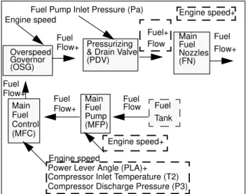
Note that EGT is exhaust gas temperature and is an inconsistent link. This implies that there is an invalid link in the fault-based knowledge. The parameters engine speed (N) and fuel flow (Wf) are expected and the sign on N is missing as expected. The partial view of the extracted MFS subsystem is shown in Figure 2.
Fig. 2. Main Fuel System model extracted by DR Note that the main fuel pump and main fuel con-trol filters extracted by DR were omitted to sim-plify the diagram. Thus, DR succeeds in extracting the 7 components (Figure 2 shows 5 and excludes the 2 filters and shows a fuel tank) and their respective connections in Phase 1. In the second phase the device dependent and device indepen-dent background knowledge is used to derive the
Overspeed Governor (OSG)
Pressurizing & Drain Valve (PDV) Main Fuel Nozzles Fuel Tank Main Fuel Pump Main Fuel Control (MFC) (MFP) (FN) Engine speed+ Engine speed Fuel Flow+ Fuel Flow Fuel+ Flow Fuel Flow+ Engine speed+ Fuel Flow+ Fuel Pump Inlet Pressure (Pa)
Fuel Flow+
Engine speed
Power Lever Angle (PLA)+ Compressor Inlet Temperature (T2) Compressor Discharge Pressure (P3)
direction and relations between the extracted parameters. Any gaps between JETA and the background knowledge are highlighted (illus-trated with dashed boxes in Figure 2) so that the fault-based knowledge can be made consistent or modified. Thus, the validating algorithm has shown errors in JETA’s fault-based knowledge, specifically, missing or extra links and one miss-ing component (the fuel tank) to be manually or automatically corrected.
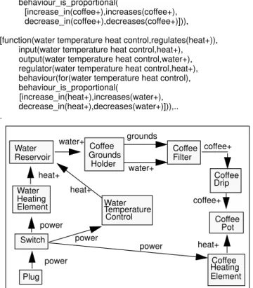
5.2 DR Coffee Maker Results & Device Model To test the generality of the DR algorithm and relax some of its assumptions, I generated a 30-node knowledge base for the diagnosis of a coffee maker (a very different device than an aircraft engine). The coffee maker device had a variety of terminal nodes (not only replace types). DR selected all terminal nodes and assumed that they represented device components. Then, as before, parental nodes were used to identify sibling nodes and connections between them. Only 3 of the node slots of the frames of fault-based knowledge were used, the node name, the child node of and the child node ranking slots. From these slots the 5 steps (with step 1 relaxed) of the DR algorithm were used to generate the model in Figure 3. A regulator, a switch, a heater, a holder and a fil-ter were the device independent component mod-els added to the library for background knowledge. In addition, 10 expressions that rep-resented the device dependent background knowledge giving the type of component and the input/output behaviour parameters were used by DR. Thus, it was possible to successfully gener-ate a component behaviour model for a full device (rather than only a subsystem) with explicit function and behaviour descriptions for each of the coffee maker components. To provide the reader with some detail, below are the DR generated component models for 2 of the 10 com-ponents, specifically for the coffee drip and water temperature heating control.
[function(coffee drip,regulates(coffee+)),
input(coffee drip,coffee+),output(coffee drip,coffee+), regulator(coffee drip,coffee+),
behaviour(for(coffee drip), behaviour_is_proportional(
[increase_in(coffee+),increases(coffee+), decrease_in(coffee+),decreases(coffee+)])), [function(water temperature heat control,regulates(heat+)),
input(water temperature heat control,heat+), output(water temperature heat control,water+), regulator(water temperature heat control,heat+), behaviour(for(water temperature heat control), behaviour_is_proportional(
[increase_in(heat+),increases(water+), decrease_in(heat+),decreases(water+)])),.. .
Fig. 3. Coffee Maker device model as extracted by DR 6 Discussion and Conclusions
Mapping fault-based knowledge (FBK) to model-based knowledge (MBK)
The DR algorithm makes the assumption that as one ascends a well-structured diagnostic hierarchy of FBK, one can extract component knowledge and behavioural MBK. This is key in discovering the relation between the components and the vari-ous layers of knowledge above them, thus identi-fying any gaps or inconsistencies and validating the KBS. In the engine fault knowledge, DR showed that a significant layer is missing in the FBK.
If one examines the knowledge extracted by DR, the lowest layer of knowledge (represented by the terminal nodes in Figure 4), is the component knowledge. The layer above that knowledge is, as assumed by DR, symptomatic knowledge that maps directly to component parameters. These parameters represent model behavioural variables. Some minor inconsistencies (missing or extra
Water Reservoir Plug Switch Water Heating Element Coffee Heating Element Coffee Filter Coffee Grounds Holder Coffee Pot Water Temperature Control Coffee Drip coffee+ power power heat+ water+ grounds water+ coffee+ heat+ power heat+ power
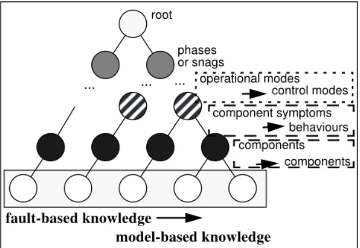
parameters which implied missing or extra links) were found in JETA at this level. However, the most significant discovery is the layer of missing knowledge above the symptomatic knowledge for components that have multiple functional modes in JETA.
These are specifically control components (e.g. the Main Fuel Control, the Overspeed Governor, etc.). These components have associated with them functional modes with a different number of respective control variables. Thus, in a specific mode, a fault in JETA may be manifested and it would be indicated by some variable. In another mode, a completely different variable may be the indicator of a fault with the component. At a higher level in the JETA hierarchy, the functional modes are related to phases of engine operation. However, the current JETA fault knowledge does not explicitly relate these component operational modes to the phases of engine operation. Given the DR acquired component models, it would not be very difficult to add this new layer of knowl-edge above the component symptom layer, and explicitly relate it to the phases of engine opera-tion.
Fig. 4. Missing Layers of knowledge in JETA
Impact of Background Knowledge Vs. Fault Knowledge
Two types of background knowledge are needed to achieve the DR algorithm results: device dependent background knowledge (DDBK) and device independent background knowledge (DIBK). DDBK provides glossary knowledge,
root phases operational modes components component symptoms ... ... ... components behaviours control modes fault-based knowledge model-based knowledge or snags
mapping the fault-based encoded name of the component to a meaningful symbolic name (this was necessary for the engine application to decode JETA syntax, but was not used for the coffee application which encoded meaningful text). The DDBK also represented any component-specific modes of operation and respective I/O variables with a plus/minus (+/-) sign indicating a direction for changes in value. DIBK is a form of a generic component type description that gets instantiated according to the extracted model. The generic component descriptions are designed to be placed in a design or model library (e.g. a CAD/CAM library) so that they may be re-used for different devices. Their description includes a function (the purpose or goal of the component, e.g. to pump, to control, to filter, etc.), inputs, outputs, regulation inputs, and a behavioural relation describing how the inputs change with respect to the outputs for particular modes of operation (proportional, inverse proportional or piece-wise linear).
Often in software engineering, lines of code are used to compare metrics of various programs. Similarly, the statistics comparing the ratios of background knowledge (BK) to fault-based knowledge (FBK) used by DR can be examined. The total fault knowledge used for the engine application is 3972 lines of code encoding 197 fault nodes. Out of this fault knowledge, in model-ling the Main Fuel System (MFS), approximately 60 fault nodes are used. The average number of lines of code per node is 20. Thus, the DR algo-rithm uses 1200 lines of JETA fault knowledge code, to model the MFS components and connec-tions. DR also uses 168 lines of code of total back-ground knowledge, of which 101 is device dependent (DDBK) and 67 is device independent (DIBK). Thus, the ratio of background knowledge to total fault knowledge is only 4.23%, and to fault knowledge used by DR for modelling the MFS is 14%. Similarly, for the coffee application, 330 lines of code or 29 fault nodes are used by DR. The total number of lines of code of background knowledge used for modelling the device are 91, of which 35 are device dependent and 56 are device independent. Thus, the ratio of
back-ground, to total fault knowledge used by DR for modelling the full coffee maker device is 28%.
Final Conclusion
This paper addresses the difficult problem of automated model acquisition for diagnosis and illustrates a new approach for the validation of fault knowledge. The DR algorithm automates generation of component models with an explicit representation of behaviour and function through the re-use of FBD knowledge and background knowledge. For a small additional investment in background knowledge, black box models for complex devices can be generated by DR through fault knowledge re-use. These models can be used to uncover gaps and inconsistencies in the original fault knowledge. DR forms a bridge between FBD and MBD knowledge to facilitate the exploitation of knowledge in hybrid systems.
Acknowledgments
I would like to acknowledge Professor Nick Dawes of the Computer and Systems Engineering Department and Pro-fessor Franz Oppacher of the School of Computer Science at Carleton University for supervising my Ph.D. thesis. I would also like to thank NRC for supporting me in complet-ing this work.
References
Abu-Hakima, S. [1994a], DR: the Diagnostic Remodeler algorithm for automated model acquisition through fault knowledge re-use, PhD thesis, Carleton University, Ottawa, Canada (1994).
Abu-Hakima, S. [1994b], Diagnostic techniques in knowl-edge-based systems: a review of approaches, applications and issues. 100 p. NRC 37142 report (1994).1
Abu-Hakima, S. [1993], Automatic Knowledge Acquisi-tion in Diagnosis. Proceedings of DX-93, Fourth Interna-tional Workshop on Principles of Diagnosis. Aberystwyth, Wales. 236-250. (1993), NRC #35111.
Abu-Hakima, S., and Oppacher, F., [1990] Improving explanations in knowledge-based systems: RATIONALE. Knowledge Acquisition journal (2). 301-343. December 1990.
Abu-Hanna, A., [1989] Dynamic system representation in model-based diagnosis. Computational Intelligence 88: Proceedings of the international conference. Milan, Italy, 26-30 September 1988. Elsevier Publishers.
Abu-Hanna, A., Benjamins, R., and Jansweijer, W., [1992] “Integrating multiple model types in model-based diagnosis”, DX-92, The 3rd International Workshop on 1.All publications with NRC numbers can be requested from edi-torial@iit.nrc.ca.
Principles of Diagnosis, Rosario, Washington, pp. 179-184, (October 12-14, 1992).
Althoff, K-D., Maurer, F., and Rehbold, R. [1990] ,“Multi-ple knowledge acquisition strategies in MOLTKE.” Current
trends in knowledge acquisition, Published by IOS,
Amster-dam, Netherlands. pp. 21-40, (1990).
Bizzari, l., Corazziari, F., Faciano, S., Gualaccini, P.G., Luminari, L., Savarese, M. and Trasatti, E., [1990] “Fault diagnosis of electronic circuits”, 10th Workshop: Expert Systems and their Applications. Specialized Conference: Artificial Intelligence and Electrical Engineering, Avignon, France, pp.115-23, (May 28-June 1, 1990).
Chandrasekaran, B. [1986], “Generic tasks in knowledge-based reasoning: high-level building blocks for expert sys-tem design”. IEEE Expert, 1(3), 23-30. (1986).
Clancey, W.J., [1986] “From GUIDON to NEOMYCIN and HERACLES in twenty short lessons: ORN final report 1979-1985”. The AI Magazine, pp. 40-60,(1986).
Davis, R. [1984], “Diagnostic reasoning based on structure and behaviour”, AI, Vol. 24, pp. 347-410 (1984).
de Kleer, J., Williams, B.C. [1987], “Diagnosing Multiple Faults”, Artificial Intelligence, vol. 32, (1987).
Goel, A., Soundararajan, N., and Chandrasekaran, B., [1978], Complexity in classificatory reasoning, Proceedings of the 6th National Conference on Artificial Intelligence: AAAI-87, Menlo Park, CA, pp. 421-25, (1987).
Halasz, M., Davidson, P., Abu-Hakima, S., and Phan, S. [1992], JETA: A Knowledge-based Approach to Aircraft Gas Turbine Engine Maintenance. Journal of Applied Intel-ligence, 2, pp. 25-46, Kluwer Academic Publishers, NRC 31832, (1992).
Hamscher, W. and Struss, P. [1990], “Model-Based Diag-nosis”, AAAI-90 Tutorial Notes, Received at the eighth national conference of artificial intelligence, Boston, Massa-chusetts. July 29, 1990. pp. 1-179, (1990).
Laurent J.-P. [1992], “Proposals for a valid terminology in KBS validation”, ECAI-92 Edited by B. Neumann. Pub-lished by John Wiley and Sons Ltd, pp. 829-34 (1992). Meisner, J., Bursch, P. and Funk, H., [1990], “Evolution of a maintenance diagnostic system”, Proceedings of the IEEE 1990 National Aerospace and Electronics Conference: NAECON 1990, Dayton, Ohio, vol. 2, pp. 520-525, (21-25 May 1990).
Nayak, P.P., and Struss, P., [1994] Modeling Physical Sys-tems: the state of the art and beyond, AAAI-94 tutorial notes, August 1994.
Sticklen, J., Chandrasekaran, B., and Bond, W.E. [1988], “Distributed causal reasoning for knowledge acquisition: a functional approach to device understanding”, 3rd AAAI sponsored Knowledge Acquisition Workshop for Knowl-edge-Based Systems, Banff, Canada, pp. 34-1 to 34-18, (1988).
Struss, P. [1989], “New Techniques in Model-based Diag-nosis”, Proceedings of Knowledge-based Computer Systems, Bombay, India, (11-13 December 1989).
van Soest, D., [1993] Modelling for model-based diagnosis. Ph.D. thesis. University of Enschede, Holland.