XVI. DIGITAL SIGNAL PROCESSING
Academic and Research Staff
Prof. Alan V. Oppenheim Dr. Russell M. Mersereau Dr. Siamak Samsam
Prof. Jonathan Allen Dr. W. Hans Schuessler
Graduate Students
Ronald H. Frazier Gary E. Kopec Elliot Singer
David B. Harris Michael R. Portnoff Jos6 M. Tribolet
Anthony P. Holt Thomas Quatieri Ernest Vincent
RESEARCH OBJECTIVES AND SUMMARY OF RESEARCH 1. Speed Transformation of Speech
U.S. Navy Office of Naval Research (Contract N00014-67-A-0204-0064) Alan V. Oppenheim, Michael R. Portnoff
One aspect of our effort to apply digital signal processing techniques to speech is the development of ahigh-quality system to implement speed transformations on speech. Our goal is to devise a scheme whereby a high-fidelity speech signal is modified so that it is perceived as identical to the original signal in all aspects except that it appears that the rate of utterance has been changed.
A system to perform such high-quality speed transformations has numerous appli-cations, such as increasing the rate of speech in "talking books" for the blind and gen-erating speech stimuli for psychoacoustical perception experiments. In contrast, it is desirable to decrease the rate of speech in applications such as language learning, speech therapy, and the transcription of poor-quality recordings of speech. Further-more, we sometimes wish to introduce adaptive changes in the rate of utterance. For example, in certain communication systems it is desirable to fit a given utterance into a time slot of given duration.
We are considering three approaches for implementing high-quality speed transfor-mations. The first approach is based on a linear-predictive analysis of speech. The predictor coefficients are used to generate a linear time-variant least-squares inverse filter and an analogous time-variant acoustic tube synthesis filter for the speech waveform. The original speech signal is played through the inverse filter to produce an error signal. The error signal is appropriately modified and then played through the synthesis filter to produce the modified speech signal.
The second approach is based on short-time Fourier analysis. The short-time Fourier spectrum is estimated for the speech waveform as a function of frequency and time. The time rate of change of this spectrum is varied and the modified spectrum is used to synthesize the modified speech signal.
The third approach is a combination of the two previous schemes. Here the analysis and synthesis of the speech is performed by using the methods of linear prediction, and the modification of the error signal is accomplished by short-time Fourier analysis and synthesis.
2. Enhancement of Degraded Speech
U.S. Navy Office of Naval Research (Contract N00014-67-A-0204-0064) Ronald H. Frazier, Alan V. Oppenheim, Siamak Samsam,
W. Hans Schuessler, Elliot Singer
We have started a new set of projects related to the enhancement of degraded speech in which the initial work is to apply variable comb filtering to track the pitch harmonics of the desired speech. An earlier investigation of this approach was carried out sev-eral years ago. Our present efforts are directed toward refining the technique and developing ways of extracting the pitch of the desired speaker automatically in a background of noise or multiple speakers. As one aspect of this work, an algorithm has been developed by which digital comb filters can be designed with passbands of arbitrary widths centered at arbitrary frequencies. The designs are obtained by converting a lowpass prototype filter by means of a general all-pass transformation. We have also developed techniques for designing the appropriate all-pass transfer function. A second aspect of this project is concerned with exploring and evaluating a class of nonlinear filtering techniques in which linear filtering is applied to a signal transformed to a function of its arc length.
3. Spectral Zeros in Linear Prediction
U. S. Navy Office of Naval Research (Contract N00014-67-A-0204-0064) Gary E. Kopec, Alan V. Oppenheim
In recent years the technique of linear predictive coding (LPC) has received con-siderable attention as a basis for analysis-synthesis telephony, but no really high-quality vocoder has yet emerged. There are two possible explanations for this. Perhaps LPC, based on an all-pole model of speech production, suffers because it cannot efficiently represent the effects of spectral zeros. Alternatively, it may be that the problem arises from poor estimation of vocal tract excitation: the so-called voiced/unvoiced decision.
We aim to address the first possibility by performing series of experiments on artificially synthesized speech of known excitation and controlled spectrum. By eliminating all errors of pitch'extraction, we can focus on the perceptual impact of explicit zero coding in a very "clean" environment. Basically, we shall compare all-pole LPC analysis with various schemes of pole-zero estimation. Subjective reproduction fidelity will be used as a performance measure.
4. Implementation of a Programmable Digital Filter
U.S. Navy Office of Naval Research (Contract N00014-67-A-0204-0064) Anthony P. Holt, Alan V. Oppenheim, Ernest Vincent
We are completing the implementation of a nonrecursive programmable digital filter for use as a preprocessing filter for audio input to a digital computer. The filter is 64t h order in a nonlinear phase configuration and 128thorder for linear phase. During the coming year we plan to investigate the design and implementation of a digital filter for which the cutoff frequency is varied by changing a single parameter. The basic concept for implementation of variable cutoff digital filters of this type is closely related to the theory of digital frequency warping.
(XVI. DIGITAL SIGNAL PROCESSING)
5. Seismic Data Analysis Using Homomorphic Filtering
U.S. Navy Office of Naval Research (Contract N00014-67-A-0204-0064)
Alan V. Oppenheim, Jos6 M. Tribolet
We have recently begun a research program to apply homomorphic deconvolution techniques to seismic data analysis. Our work has been concerned with efficient techniques for computation of the complex cepstrum, and to investigating the potential for combining homomorphic techniques with the techniques of predictive deconvolution. During the coming year we shall investigate some algorithms using both real and syn-thetic seismic data.
6. Two-Dimensional Digital Filter Design
National Science Foundation (Grant GK-31353) David B. Harris, Russell M. Mersereau, Alan V. Oppenheim, Thomas Quatieri
We have been exploring a number of techniques for the design of two-dimensional digital filters. Among these are use of transformations as suggested by McClellan, equiripple Finite Impulse Response (FIR) designs using the first algorithm of Remez, and design of Infinite Impulse Response (IIR) filters whose transfer functions have separable denominators.
The McClellan transformation technique converts a one-dimensional linear phase FIR filter into a two-dimensional linear phase FIR filter, by substituting a function of two frequency variables for the single frequency variable of the one-dimensional filter. The frequency response of the two-dimensional filter then depends in a rather simple way upon the frequency response of the one-dimensional filter and upon the specific transformation used. We have developed an algorithm for choosing the transformation parameters efficiently and are now comparing the performance of these filters with other two-dimensional design algorithms.
We have also developed an algorithm for finding the optimum equiripple two-dimensional linear phase approximation to an arbitrary frequency response. This uses the first algorithm of Remez which is modified to reduce the design time. The algorithm appears to be efficient, but further modifications can probably be made to increase the efficiency further. Convergence of the modified algorithm remains to be proved.
We have also been concerned with the design of IIR filters with transfer functions that have separable denominators. Unlike more general IIR filters, with such filters, it is straightforward to guarantee the stability and implementation. We have found an algorithm for designing these filters, but their performance remains to be com-pared with more general IIR and FIR filters.
7. Analysis and Design of Digital Filter Structures National Science Foundation (Grant GK-31353) Ronald E. Crochiere, Alan V. Oppenheim
Our research on digital filter structures involves the investigation of general digital network properties and the analysis of specific digital filter structures. During the past six months, a doctoral thesis, entitled "Digital Network Theory and Its
Application to the Analysis and Design of Digital Filters," was completed by Ronald Crochiere. This research has produced new major results, including a matrix formu. lation for digital networks, an approach to digital filter sensitivity analysis, the intro-duction of precedence relations for evaluating parallelism in the implementation of digital filters, and the development of a computer-aided network analysis program. During the coming year, our research in the analysis of digital filter structures will focus primarily on an attempt to understand the limit-cycle behavior of digital filters.
8. Small Signal Processor
U.S. Navy Office of Naval Research (Contract N00014-67-A-0204-0064) Jonathan Allen
Design of a small signal processor (SSP) has been completed, and all parts obtained. Layout of the large, 24 X 24 multiplier (involving 160 arithmetic-logic unit packages) is complete, and the remaining layout will be facilitated by computer layout and wire-list programs. Construction should be complete during the first quarter of 1975.
The SSP is unique in that it is a "straight" 3-address design, using two 1024 X 24 data memories, and a separate 1024 X 54 program memory. The 24-bit data word length is intended for research applications for which high precision is required. The machine includes a (X * Y) + Z functional unit that can multiply two 24-bit numbers and add a third number (Z) to that result in 120 ns. Extensive shifting and rotating commands are pro-vided, as well as a complete arithmetic-logic unit capability. Unlike many machines of this class, a block transfer DMA facility is provided, the status of which can be moni-tored at any time by the program. A timing clock, and direct D/A connections, are also
included. The logic is all in ECL 10k.
We believe that this machine will provide many features that are missing in small signal-processing computers. The ease of programming, 24-bit word length, relatively large memory, and convenient I/O interface combine with high speed to provide a very useful machine. Additionally, the console provides the ability to display the contents
of any specified location while the machine is running, or to halt whenever that location is addressed. We expect the SSP to provide an extremely fast, powerful, and conve-nient signal-processing capability for laboratory use.
(XVI. DIGITAL SIGNAL PROCESSING)
A. COMPARISON OF DIGITAL FILTER STRUCTURES ON THE BASIS OF COEFFICIENT WORD LENGTH
National Science Foundation (Grant GK-31353) Ronald E. Crochiere
1. Introduction
In this report we compare several different classes of recursive filter structures which have been proposed recently by numerous authors. Comparison is made primar-ily on the basis of coefficient word length and on the number of multiplies and adds
required for various structures. Analyses of these structures were performed with the aid of the general-purpose computer-aided digital network analysis package (CADNAP).
For the comparison2 we chose an eighth-order elliptic bandpass filter (Fig. XVI-1).
1+2ep -I+EP I- ep
' Fig. XVI-1.
2i, 41ZZ 'Z Filter design specification for the
eighth-:, -:! , order bandpass example.
0 I WP Wp2 ' r
(p 0.015 7 816 e,0.00526063= wpl=0.4111111 7 wsi0.3847015 7
wp2=0.4666667 r w,2-0.4944444 7
Elliptic filters are widely used, and hence we are able to show that for certain classes of filter designs, such as elliptic and bandpass transformed designs, the number of mul-tiplies (in some classes of structures) can be reduced by taking advantage of the
prop-erties of these designs.
2. Filter Structure Examples
Thirteen different recursive filter structures were chosen for comparison (see Table XVI-1). Although these are not all of the known structures that are possible, they were chosen to give a typical cross section of the methods and philosophies for recur-sive filter structure synthesis. It is hoped that this comparison will provide further insight into promising methods for further research and thereby stimulate investigation in these areas.
as the "canonic form"), the cascade form structure, and the parallel form structure, where the cascade and parallel forms are implemented with first- and/or second-order direct form II sections. These three classes of structures, in various forms, were the first types of structures to be considered in digital signal processing. Their properties
3-6 have been studied extensively and are well known.
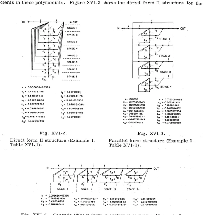
The direct form structures are synthesized from the ratio of polynomials comprising the system function and the coefficients in the structure take the values of the coeffi-cients in these polynomials. Figure XVI-2 shows the direct form II structure for the
OUT -l z SSTAGE STAGE I2 C3 4 Z-1 STAGE 3 C5 -cC 6 - - -SSTAGE 4 C7 C - -2 STAGE 5 c c 9 I .. 10. STAGE 6 II C1 ---I STAGE 7 C13 14 --STAGE 8 C15 ---d k I C2 -C4 C3 STAGE I -C c -I STAGE 2 S C9 2z- C STAGE3
C13
C14 C5 16 Z1 c15 STAGE 4 C9 Z c2 =- 1.387818861 c4 = 3.990834175 C6 =-3.801090558 C8 = 5.978059098 c10=-3.801090558 Cl2" 3.990834175 C 14 - 1.387818861 k = 0.10000 CI . 0.2034508401 c 2= 0.2855823838 C3. 0.9026252904 c4 -0.9116860616 c5 0.182701196 C6 • 0.4457342317 c7 -0.9457352763 c8=-0.913078673 d * 0.07220910762 C9 = -0.2052671178 C0 - 0.196901665 c,1 --0.2413054652 C12 - -0.9695353354 C13 -0.1965294023 C14 * 0.5515388641 Cls5 0.298888793 C16 --0.9705899009 Fig. XVI-2.Direct form II structure (Example 1, Table XVI-1). k I I I IN -' Ct C2 C4 C Z Z I C3 C6 STAGE I STAGE 2 k - 0.005656462366 C, * 0.2855823838 C4 = 0.4457342317 C2 * 0.4512591755 C5 = -1.09869455 C3 * -0.9116860616 C6 * -0.913078673 Fig. XVI-3.
Parallel form structure (Example 2, Table XVI-1). ZI I Z I C9 I CI2 STAGE 3 STAGE 4 C7 - 0.196901665 CIO = 0.5515388641 C . -0.0099665157 C - -0.7304169706 C 9 = -0.9695353354 C12= -0.9705899009
Fig. XVI-4. Cascade (direct form II sections) structure (Example 3,
Table XVI-1). k = 0.005656462366 cI 1.479757145 c3 ,-4.548129731 c5 = 4.352241828 c7 =-6.802822262 C9 = 4.094876357 CII =-4.026604318 C =-0.7833447265 C15' 1.232007442
(XVI. DIGITAL SIGNAL PROCESSING)
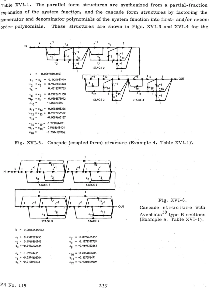
eighth-order bandpass filter specified in Fig. XVI-1. Structure characteristics in this figure and many of those that follow are given in detail in the referenced examples in Table XVI-1. The parallel form structures are synthesized from a partial-fraction expansion of the system function, and the cascade form structures by factoring the numerator and denominator polynomials of the system function into first- and/or second-order polynomials. These structures are shown in Figs. XVI-3 and XVI-4 for the
k z- 1 k = 0.006958654501 c1 = c4 = 0.1427911919 2 = c3 = 0.9440851323 C5 = 0.4512591755 c6 = c9 = 0.2228671158 -c7 = c8 = 0.9291979992 c10 = -1.09869455 C11 = c14 = 0.0984508325 "c12 = c13 = 0.9797156572 c15 = -0.0099665157 c16 = c1 9= 0.275769432 ' 17 = c18 = 0.9458018404 c20 = -0.7304169706
Fig. XVI-5. Cascade (coupled form) structure (Example 4, Table XVI-1).
STAGE 3 STAGE 4
Fig. XVI-6.
OUT Cascade structure with
10
Avenhaus type B sections (Example 5, Table XVI-1).
k = 0.005656462366 cI = 0.4512591755 c2 = 0.6969890843 c3 = -0.9116860616 c4 = -1.09869455 C5 = -0.5574603304 c6 = -0.913078673 c7 = -0.0099665157 8 = 0.1872387759 c9 = -0.9695353354 cI0 = -0.7304169706 11= -0.157396471 c2 = -0.9705899009
INI
IN...
2
_ g
OUT k = 0.005656462366 cI = 0.4512591755 c2 = 0.1198547195 c3= 0.7368415593 = -1.09869455 = -0.1331188504 = -0.6529603187 c7 =-0.0099665157 c8 = 0.1629691618 C9 = 0.1869351493 C10 = -0.7304169706 C11 -0.1644141906 12= -0.1788781065Fig. XVI-7. Cascade structure with Avenhaus1 0 type F sections (Example 6, Table XVI-1).
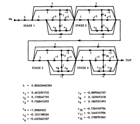
eighth-order bandpass example. In addition to the direct form II sections for the cascade structures, many other possible network configurations for implementing these sections have been proposed.4, 7 - 1 0 Three different forms of second-order sections were
selected from these possibilities for the eighth-order bandpass example. They are the coupled form sections4,11 and the network configurations B and F proposed by Avenhaus10 (see Figs. XVI-5, XVI-6, and XVI-7).
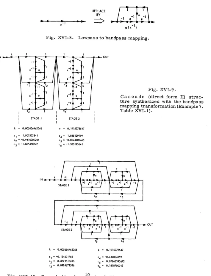
In the synthesis of bandpass filters such as the example that we are considering we can first synthesize a lowpass prototype of the filter and then transform this function to
12 -1
a bandpass function.l2 In this transformation we replace all functions z with the all-pass mapping g(z-1):
-1 -1 z (z -la)
replaced ) z-1
replaced 1 - az
where a is the mapping parameter. This same process can be incorporated into the synthesis of filter structures by first synthesizing an appropriate lowpass filter and then replacing all delays in the structure with a circuit (Fig. XVI-8) that realizes the mapping in (1). The parameter a determines the bandpass center frequency Wo to which the dc value of the lowpass filter function is mapped and can be expressed as
-1 z Fig. XVI-8. REPLACE I 1 BY I -1 (Z-1 ) g (z )
Lowpass to bandpass mapping.
I
b OUT
Fig. XVI-9.
Cascade (direct form II)
struc-ture synthesized with the bandpass mapping transformation (Example 7, Table XVI-1). STAGE 2 k = 0.005656462366 = 1.907532841 = -0.9410209204 = -1.865468242 a = 0.1915378547 c4 = 1.818129999 c5 = -0.8324402465 c, = -1.380195641 k = 0.005656462366 C1 = -0.134531758 c2 = 0.3621618696 c3= 0.0924671586 a = 0.1915378547 C4 = c5 = c6 = -0.619804359 0.07868393672 0.1818700012
Fig. XVI-10. Cascade (Avenhaus10 circuit E) structure synthesized with the bandpass mapping transformation (Example 8, Table XVI-1).
STAGE I
ON
I
--
I --_1I
-
-,
,:I-":I/
Z ZZ
cos o = a. (2)
This synthesis approach is illustrated in Figs. XVI-9 and XVI-10. The example in Fig. XVI-9 was synthesized from a fourth-order cascade structure with direct form II
sections. The example in Fig. XVI-10 was synthesized from a fourth-order cascade structure with second-order sections in the form of circuit E proposed by Avenhaus. 10
Another way of representing the system function of a filter is in terms of continued fraction expansions. Mitra and Sherwood1 3 demonstrated that 4 basic forms of these expansions are possible and that from these expansions we can construct a class of structures. Two of these structures, type IA and type IB, were synthesized for the eighth-order bandpass example (Figs. XVI-11 and XVI-12). The continued fraction expansion of type IIA was not realizable for this example and the structure corresponding to type IIB is noncomputable.
Ladder or lattice structures have received considerable attention recently.
14-23 CIN IN L c2 z-1 c 3 c4 z-1 C5 c6 z C 7 c7 C8 z- 1 C9 10 z C1 1 c 12 z-1 C13 -1 c 14 z- 1 c15 c16 z -c1 7 OUT STAGE 1 STAGE 2 STAGE 3 STAGE 4 STAGE 5 STAGE 6 STAGE 7 c = 0.005656462366 c2 = 0.0919382834 c3 = -49.83636203 c4 = -0.1152951246 C5 = 4.789010497 c6 = -0.07982020996 c7 = 16.77636663 8 = 0.1244561442 c9 = -1.893836272 c10 = -0.00626901611 c1 1 = 3.833751971 c12 = 23.59416286 '13 = -3.825612822 '14 = 0.002102572645 C1 5 = -104.9491082 IN CI C16 = -0.02701849245 STAGE 8 ci7 = 75.86358186 C 2 fI C3 C4 C6 Z-I C7 Ca Z-I C9 Cl Z-I C11 Z-1 C13 Z-1 Cl5 C1 6 z- C 17 C1 8 OUT STAGE I STAGE 2 0.0002828231183 25.53154355 -0.2117906668 1.017015349 C5 = 0.1736820909 C6 = -12.7837888 STAGE 3 C7 = 0.4649449432 C8 = -1.606209516 STAGE 4 STAGE 5 Cg = -0.2767502193 CIO = 7.610142205 CI = 3.939247317 C12 = -0.4301416747 STAGE C3 = -0.9905202523 C14 = 0.6779657016 C15 -21.82668197 C6 = -0.4193825017 C17 0.2481853405 STAGE 8 C1 = 0.4028556869 Fig. XVI-11.
Continued fraction expansion structure type IA (Example 9, Table XVI-1).
Fig. XVI-12.
Continued fraction expansion structure type IB (Example 10, Table XVI-1).
(XVI. DIGITAL SIGNAL PROCESSING)
These structures are not synthesized by representing the system function in terms of some form of factorization or expansion. Instead, the mechanisms behind the synthesis procedures for these structures are closely related to the two-port network synthesis techniques associated with conventional analog RLC circuits.
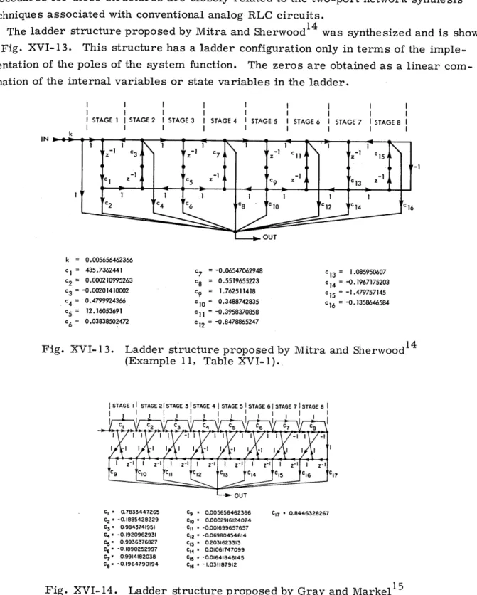
The ladder structure proposed by Mitra and Sherwood1 4 was synthesized and is shown in Fig. XVI-13. This structure has a ladder configuration only in terms of the imple-mentation of the poles of the system function. The zeros are obtained as a linear com-bination of the internal variables or state variables in the ladder.
I I I I I STAGE I ISTAGE 2 k I I I I I I
I STAGE 3 I STAGE 4 I STAGE 5
I I I
II I
I I
I STAGE 6 I STAGE 7 I STAGE 8
I I I c7 =-0.06547062948 c8 = 0.5519655223 C9 = 1.762511418 C10 = 0.3488742835 11= -0.3958370858 c12= -0.8478865247 S13 = 1.085950607 C1 4 = -0.1967175203 c5 = -1.479757145 6 = -0.1358646584
Fig. XVI- 13. Ladder structure proposed by Mitra and
(Example 11, Table XVI-1). Sherwood
1 4
STAGE II STAGE 21STAGE 31 STAGE 4 STAGE 5 1 STAGE 6 STAGE 7 1 STAGE 8 I
. -- b, OUT 0.005656462366 0.0002916124024 -0.001699657657 -0.06980454614 0.2031623313 0.01061747099 -0.01641846145 -1.031187912 C17= 0.8446328267
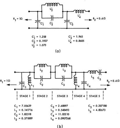
14. Ladder structure proposed by Gray and Markel1 5 (Example 12, Table XVI-1).
PR No. 115 = 0.005656462366 = 435.7362441 = 0.000210995263 = -0.00201410002 = 0.4799924366 = 12.16053691 = 0.03838502472 CI - 0.7833447265 C2 -0.1885428229 C3 - 0.9843741951 C4 * -0.1920962931 C5 - 0.9936376827 C6 -0.1890252997 C7, 0.9914182038 Cg8 - 0.1964790194 Fig. XVI-239
A second type of ladder structure, synthesized according to methods proposed
by Gray and Markel, 15 is shown in Fig. XVI-14. This structure also has a ladder con-figuration only in terms of the implementation of the poles of the system function, and the zeros are obtained as a linear combination of the internal "state variables" in the structure.
Another procedure for the synthesis of ladder structures was proposed by Fettweis,16-19 and we have proposed21 a modification for implementing the zeros in these structures. For this class of structure the synthesis procedure is not only similar
to that for analog two-port circuits but, in fact, it is obtained by starting from an LC ana-log ladder design and appropriately transforming this design into a digital ladder design.
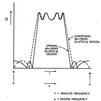
To perform the synthesis of the eighth-order bandpass example, we started with a fourth-order LC lowpass prototype (Fig. XVI-15a). This design was obtained by using a standard set of tables of Saal.2 4 This structure was then transformed to the bandpass structure in Fig. XVI-15b, by using conventional transformations for LC ladder designs.24 An important characteristic of this bandpass LC structure is that the gain of the structure is zero at dc and at infinity. This is in contradiction to the even-order optimal bandpass elliptic designs that require that the gain at these frequencies be finite.
RI= 10 R2 =0.60
c i
TC
c
C- = 1.258 C = 1.965 C = 0.1937 L = 0.8605 L = 1.073 (a) 12 1L3 RI= R2= 0.60 c1 L 2 C3 4 C II I I I II STAGEI 1 STAGE 2 I STAGE 3 ISTAGE 4 I STAGE 5
I I I I I C1 = 7.05639 C3 = 2.68897 C5 = 0.207180 L1 = 0.141716 L3 = 0.548493 L5 = 4.82673 C2 = 1.82318 C4 = 11.02210 L2 = 0.371889 L4 = 0.0907268 (b)
Fig. XVI-15. (a) Normalized fourth-order LC lowpass prototype.
(XVI. DIGITAL SIGNAL PROCESSING)
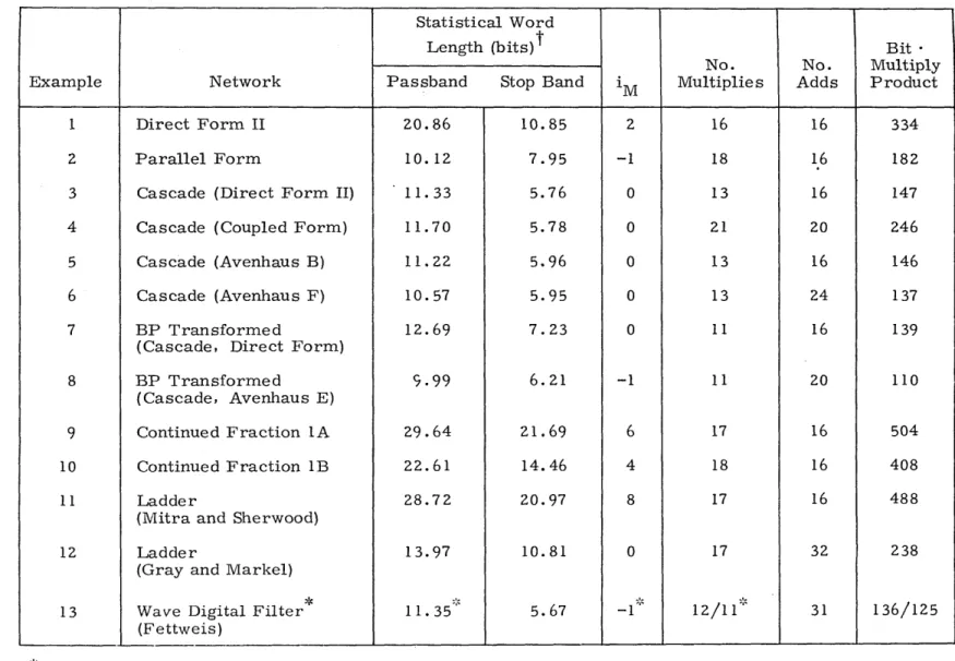
In fact, it is not possible to realize the optimal elliptic designs for even-order filters by using this class of LC structures (odd-order optimal elliptic designs present no prob-lems). In practice, the optimal even-order elliptic designs are transformed to slightly less than optimal designs in a manner such that the largest zero in the frequency response is mapped to infinity and the smallest zero, for bandpass designs, is mapped to dc. This is illustrated in Fig. XVI-16. Because of this problem we could not synthe-size an eighth-order digital ladder structure of this type for our specifications. Instead,
ITI
f = ANALOG FREQUENCY w = DIGITAL FREQUENCY
Fig. XVI-16. Comparison of optimal eighth-order elliptic bandpass filter and suboptimal design for LC ladder structure.
I III
I STAGEI STAGE2 STAGE 3 STAGE 4 STAGE 5
I .I I -I I -I I I -I =1 I I I I ?I fL- I ?OT
IN
kIj
OU
wEcb Ic99 I/k I AUX OUrT "SEE TEXT k * 1.31194961 Cl - 0.06502370945 C2 " 0.2235692269 C3 * 0.5809284606 C4* 0.1626985222 C3 I I 1 II: _ C5 - 0.007805575218 C6 - 0.0574957168 C7 • -0.1915378541 CS - 0.0003565321277 ' I -I AUX IN Cg - -0.3698270573 CIO --0.1915378541 CII - 0.1915378541Fig. XVI- 17. Wave digital filter structure (Example 13, Table XVI-1).
OUT V b.- - -- --Cl --- --- ---A f OD
I
owwe used the nearest suboptimal eighth-order design in the tables of Saal24 which
cor-responded to the LC structures in Fig. XVI-15. The equivalent digital design specifi-cations for this analog structure corresponded to
E = 0.01623 E = 0.0066705 p s O = 0.4111111 ? s = 0.3839368
7r
pl sl p2 =0.4666667 7 ¢s2 = 0.4952625 T. 17, 18Using techniques suggested by Fettweis and Sedlmeyer and our own modifica-21
tion for implementing zeros, we transformed the analog ladder design of Fig. XVI-15b to the wave digital filter configuration shown in Fig. XVI-17.
3. Comparison of Recursive Filter Structure Characteristics
We shall now interpret our analyses of the recursive filter structures whose char-acteristics are summarized in Table XVI-1.
a. Coefficient Word Length
The coefficient word lengths of these structures are compared on the basis of the fixed-point statistical word length.2 They are given for relative errors R = 1 (see Fig. XVI-1) and confidence factors y = 0. 95 (i. e., x= 2). The statistical word length for each structure was determined separately for the passband and stop band in order to obtain a more general picture of the overall sensitivity properties of the structure.
For each structure the value iM used in the statistical word length definition is given, i
where 2 is the power of 2 represented by the most significant bit in the coefficient word length. This value iM , in general, is different for different structures. It is
chosen so that the largest value of the magnitudes of the coefficients in the structure is
iM +1 i
within the range 2 and 2 (exclusive of the gain constant).
In general, we found for this bandpass example that the direct form structure, the continued fraction form structures, and the ladder structure of Mitra and Sherwood required considerably larger coefficient word lengths. The structures with the lowest
coefficient word lengths were the parallel form, the cascade (Avenhaus F) form, and the bandpass transformed structure designed from a cascade (Avenhaus E) lowpass
pro-totype.
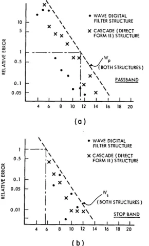
The statistical word length for the wave digital filter structure is essentially the same as that of the cascade (direct form II) structure in both the passband and the stop band. When we rounded the coefficients in fixed-point arithmetic, however, we found that in the passband the wave digital filter structure required approximately 3 bits less for a
Table XVI-1. Comparison of recursive filter structure characteristics. Statistical Word
Length (bits) Bit *
No. No. Multiply
Example Network Passband Stop Band iM Multiplies Adds Product
1 Direct Form II 20.86 10.85 2 16 16 334
2 Parallel Form 10.12 7.95 -1 18 16 182
3 Cascade (Direct Form II) 11.33 5.76 0 13 16 147
4 Cascade (Coupled Form) 11.70 5.78 0 21 20 246
5 Cascade (Avenhaus B) 11.22 5.96 0 13 16 146
6 Cascade (Avenhaus F) 10.57 5.95 0 13 24 137
7 BP Transformed 12.69 7.23 0 11 16 139
(Cascade, Direct Form)
8 BP Transformed 9.99 6.21 -1 11 20 110
(Cascade, Avenhaus E)
9 Continued Fraction
LA
29.64 21.69 6 17 16 50410 Continued Fraction IB 22.61 14.46 4 18 16 408
11 Ladder 28.72 20.97 8 17 16 488
(Mitra and Sherwood)
12 Ladder 13.97 10.81 0 17 32 238
(Gray and Markel)
13 Wave Digital Filter 11. 35 5.67 -1 12/11 31 136/125
(Fettweis)
See text.
X\\
S \ * WAVE DIGITAL
10 \ FILTER STRUCTURE
X \
5 X CASCADE (DIRECT
X FORM II) STRUCTURE
0 X\ S 0.5 \ P S ' ( BOTH STRUCTURES) 01 X\ PASSBAND 0.1 'X 0.05 - 1 X 4 6 8 10 12 14 16 18 20
(a)
\ WAVE DIGITAL FILTER STRUCTURE - - \X CASCADE (DIRECT0.5 'x \ FORM II) STRUCTURE
0.1 - \ 0.05 - \ S\ WW X (BOTH STRUCTURES) 0.01 I XX X\ STOP BAND I
II
I I I I I 4 6 8 10 12 14 16 18 20 (b)Fig. XVI-18. Comparison of the actual coefficient word length for the wave digital filter structure and the cascade (direct form II) struc-ture: (a) passband, (b) stop band.
given relative error than the cascade structure, provided that the coefficients were not "grossly quantized" so that the relative errors exceeded approximately 1 or 2. This can be observed in Fig. XVI-18a. For the stop band, as seen in Fig. XVI-18b, the word lengths are approximately the same. Thus it appears that the statistical word length for the wave digital filter structure is somewhat overestimated in the passband.
b. Multiplies, Adds, and Bit * Multiplier Products
The number of multiplies and adds required for each structure is tabulated in Table XVI-1. The bandpass transformed structures and the wave digital filter structure could each be implemented with 11 multiplies. For the cascade structures, except the cascade (coupled form) structure, the number of multiplies was 13. The rest of the struc-tures generally required approximately 17 multiplies, which is the number of degrees of freedom necessary to specify the poles and zeros of an arbitrary eighth-order system function with complex poles and zeros in conjugate pairs.
(XVI. DIGITAL SIGNAL PROCESSING)
The number of adds in many of the structures was 16. For those structures where we could obtain lower coefficient word lengths than in the cascade (direct form II) struc-ture (Examples 6, 8, and 13), we found that it was generally obtained at the expense of
increasing the number of adds and the complexity of the structure.
To obtain a crude estimate of the total amount of computation involved in each struc-ture, we evaluated the bit -multiplier products (see Table XVI-1). The number of bits was taken as the passband statistical word length.
c. Modularity and Complexity of Structures in Terms of Hardware
The modularity in a digital structure may be defined as the topological redundancy in the structure. Most structures exhibited a form of modularity that is identical from stage to stage. The only exception is the wave digital filter structure in which only some of the stages are identical. The bandpass transformed structures exhibited a dual form of modularity. They are identical from stage to stage and also in the bandpass mapping networks which replace the delays in the lowpass prototype.
4. Other Comments
The comparison of the structures made in this report has been primarily on the basis of coefficient word length and on the number of multiplies and adds required for the structures. These attributes are clearly important in the choice of a filter structure, but they are not the only factors to be considered. Of equal importance are the issues of round-off noise, dynamic range, and limit cycle effects. Considerable work has been done in these areas by Oppenheim, Weinstein, Kaiser, Jackson, Liu, and others.5, 6 Although these issues have not been considered in this report, it is important to men-tion them so that our results may be viewed in proper perspective to the overall issues of filter structure synthesis.
References R.
R. E. Crochiere, "Digital Network Theory and Its Application to the Analysis and Design of Digital Filters," Ph. D. Thesis, Department of Electrical Engineering, M.I.T., April 1974.
2. R. E. Crochiere, "A New Statistical Approach to the Coefficient Word Length Prob-lem for Digital Filters," presented at the Arden House Workshop on Digital Signal Processing, Harriman, New York, January 14-17, 1974 and at the IEEE Interna-tional Symposium on Circuit Theory, San Francisco, California, April 21-24, 1974; (to appear in IEEE Trans. on Circuit Theory).
3. J. F. Kaiser, "Digital Filters," in F. F. Kuo and J. F. Kaiser (Eds.), Systems Analysis by Digital Computer (John Wiley and Sons, Inc., New York, 1966), Chap. 7. 4. B. Gold and C. M. Rader, Digital Processing of Signals (McGraw-Hill Book
Com-pany, New York, 1969).
5. A. V. Oppenheim and R. W. Schafer, Digital Signal Processing (Prentice-Hall, Inc.,
6. L. R. Rabiner and C. M. Rader, (Eds.), Digital Signal Processing (IEEE Press, New York, 1972).
7. L. B. Jackson, "On the Interaction of Roundoff Noise and Dynamic Range in Digital Filters," Bell Syst. Tech. J. 49, 159-184 (1970).
8. L. B. Jackson, "Roundoff-Noise Analysis for Fixed-Point Digital Filters Realized in Cascade on Parallel Form," IEEE Trans., Vol. AU-18, No. 2, pp. 107-122, June 1970.
9. S. R. Parker and S. Hess, "Canonic Realizations of Second-Order Digital Filters
Due to Finite Precision Arithmetic," IEEE Trans., Vol. CT-19, No. 4, pp.
410-413, July 1972.
10. E. Avenhaus, "A Proposal to Find Suitable Canonical Structures for the
Implemen-tation of Digital Filters with Small Coefficient Word Length," Nachrichtentechn. Z., Vol. 25, pp. 377-382, August 1972.
11. H. W. Schiissler, Digitale Systeme zur Signalverarbeitung (Springer Verlag, Berlin,
West Germany, 1973).
12. A. G. Constantinides, "Spectral Transformation for Digital Filters," Proc. IEE 117, 1585-1590 (1970).
13. S. K. Mitra and R. J. Sherwood, "Canonic Realizations of Digital Filters Using the
Continued Fraction Expansion," IEEE Trans., Vol. AU-20, No. 3, pp. 185-194, August 1972.
14. S. K. M1itra and R. J. Sherwood, "Digital Ladder Networks," IEEE Trans., Vol.
AU-21, No. 1, pp. 30-36, February 1973.
15. A. H. Gray and J. D. Markel, "Digital Lattice and Ladder Filter Synthesis," IEEE Trans., Vol. AU-21, No. 6, pp. 491-500, December 1973.
16. A. Fettweis, "Some Principles of Designing Filters Imitating Classical Filter
Structures," IEEE Trans., Vol. CT-18, No. 2, pp. 314-316, March 1971.
17. A. Fettweis, "Digital Filter Structures Related to Classical Filter Networks," Arch. Elekt. bertrag., Vol. 25, pp. 79ff, February 1971.
18. A. Sedlmeyer and A. Fettweis, "Realization of Digital Filters with True Ladder Configuration," Proc. International Symposium on Circuit Theory, Toronto, Canada,
9-11 April 1973, pp. 149-152; see also Int. J. Cir. Theor. Appl. 1, 5-10 (1973).
19. A. Fettweis, "Pseudopassivity, Sensitivity and Stability of Wave Digital Filters,"
IEEE Trans., Vol. CT-19, No. 6, pp. 668-673, November 1972.
20. R. E. Crochiere, "Digital Ladder Structures and Coefficient Sensitivity," IEEE
Trans., Vol. AU-20, No. 4, pp. 240-246, October 1972.
21. R. E. Crochiere, "On the Location of Zeros and a Reduction in the Number of Adds in a Digital Ladder Structure," IEEE Trans., Vol. AU-21, No. 6, pp. 551-552, December 1973.
22. A. Chu and R. E. Crochiere, "Comments and Experimental Results on Optimal Digital Ladder Structures," IEEE Trans., Vol. AU-20, No. 4, pp. 317-318, Octo-ber 1972.
23. K. Renner and S. C. Gupta, "On the Design of Wave Digital Filters with Low Sensi-tivity Properties," IEEE Trans., Vol. CT-20, No. 5, pp. 555-567, September 1973. 24. R. Saal, "Der Entwurf von Filtern mit Hilfe des Kataloges normierter Tiefpisse,"
Bachnang/Wrtt, Western Germany, Telefunken GmbH, 1961, see p. 32, for circuit
CO425b: 0 = 32, Q2 = 2.019399, A = 43.7.