Directed self-assembly of a two-state block copolymer system
The MIT Faculty has made this article openly available.
Please share
how this access benefits you. Your story matters.
Citation
Do, Hyung Wan, et al. “Directed Self-Assembly of a Two-State Block
Copolymer System.” Nano Convergence, vol. 5, no. 1, Dec. 2018. ©
2018 The Authors
As Published
https://doi.org/10.1186/s40580-018-0156-z
Publisher
Springer Singapore
Version
Final published version
Citable link
http://hdl.handle.net/1721.1/118348
Terms of Use
Creative Commons Attribution
RESEARCH
Directed self-assembly of a two-state
block copolymer system
Hyung Wan Do
1,2, Hong Kyoon Choi
3,4, Karim R. Gadelrab
3, Jae‑Byum Chang
3,5, Alfredo Alexander‑Katz
3,
Caroline A. Ross
3and Karl K. Berggren
1*Abstract
In this work, ladder‑shaped block copolymer structures consisting of parallel bars, bends, and T‑junctions are formed inside square confinement. We define binary states by the two degenerate alignment orientations, and study proper‑ ties of the two‑state system. We control the binary states by creating openings around the confinement, changing the confinement geometry, or placing lithographic guiding patterns inside the confinement. Self‑consistent field theory simulations show templating effect from the wall openings and reproduce the experimental results. We dem‑ onstrate scaling of a single binary state into a larger binary state array with individual binary state control.
Keywords: Block copolymers, Self‑assembly, Graphoepitaxy, Nanostructures, Lithographic confinement
© The Author(s) 2018. This article is distributed under the terms of the Creative Commons Attribution 4.0 International License (http://creat iveco mmons .org/licen ses/by/4.0/), which permits unrestricted use, distribution, and reproduction in any medium, provided you give appropriate credit to the original author(s) and the source, provide a link to the Creative Commons license, and indicate if changes were made.
1 Introduction
Block copolymer self-assembly in thin films can spon-taneously generate periodic nanoscale patterns such as hexagonal arrays of dots or parallel lines, which have been proposed for applications such as nanoporous fil-tration membranes [1, 2], plasmonic structures [3, 4], integrated circuit fabrication [5–7], and magnetic stor-age media [8–10]. Many of these applications require the nanoscale features to have long-range order or to form specific non-periodic structures with low defect density. Directed self-assembly (DSA) addresses these issues by using graphoepitaxial [11–14] and/or chemoepitaxial [15–19] templates, fabricated by conventional lithogra-phy techniques, to guide the self-assembly of thin films of block copolymers. Various microelectronic device-oriented features such as concentric rings, bends, jogs, terminations, and T-junctions have been made, and these patterns have subsequently been transferred into functional materials to fabricate structures such as metal nanowire ring arrays [20–22] or parallel fins for field-effect transistors [7, 23, 24].
Common templates used for DSA include one-dimen-sional features (trenches or chemical stripe patterns), or two-dimensional features (pits or chemically pat-terned regions). Although the templating effect from trench confinement has been well studied [25–27], two-dimensional templates provide a wider set of geometries to guide block copolymer self-assembly, and can lead to formation of multiple degenerate structures. For exam-ple, concentric ring structures have been self-assembled inside symmetric confinements [20, 21], and we recently demonstrated nanoscale Archimedean spirals with spe-cific chirality formed inside circular pits [28]. By studying such block copolymer systems that have energetic degen-eracy, graphoepitaxial pattern control inside two-dimen-sional templates can be better understood for lithography applications. Moreover, by assigning different states or bits to the two degenerate morphologies, the resulting block copolymer patterns could act as a physical read-only memory.
This article describes DSA of block copolymer films within templates of different polygonal shapes. In square templates, two degenerate morphologies can form, and the presence of junctions between the templates breaks the degeneracy. We describe the properties of the binary states including distribution, correlation, and defect tolerance. We present three methods for control-ling the binary state orientations and demonstrate the
Open Access
*Correspondence: [email protected]
1 Department of Electrical Engineering and Computer Science,
Massachusetts Institute of Technology, Cambridge, MA 02139, USA Full list of author information is available at the end of the article
Page 2 of 9 Do et al. Nano Convergence (2018) 5:25
propagation of a single binary state into a larger array with orientation control.
2 Results and discussion
We first demonstrate the morphologies of a block copolymer film within polygonal templates. The block copolymer is a 45.5 kg/mol cylindrical morphology poly(styrene-block-dimethylsiloxane) (PS-b-PDMS) (SD45). Thin films of SD45 microphase separate into a layer of PDMS cylinders with in-plane orientation sur-rounded by a PS matrix, and a wetting layer of PDMS at the air interface. Electron-beam lithography was per-formed using a hydrogen silsesquioxane (HSQ) resist on silicon substrates to fabricate topographic features of various geometries. The topographic templates were chemically functionalized with a hydroxyl-terminated PS
brush. SD45 block copolymer was spin coated onto the substrate to a thickness of 27 nm, solvent annealed in a vapor of toluene and heptane, and reactive-ion etched to reveal a pattern consisting of oxidized PDMS cylinders.
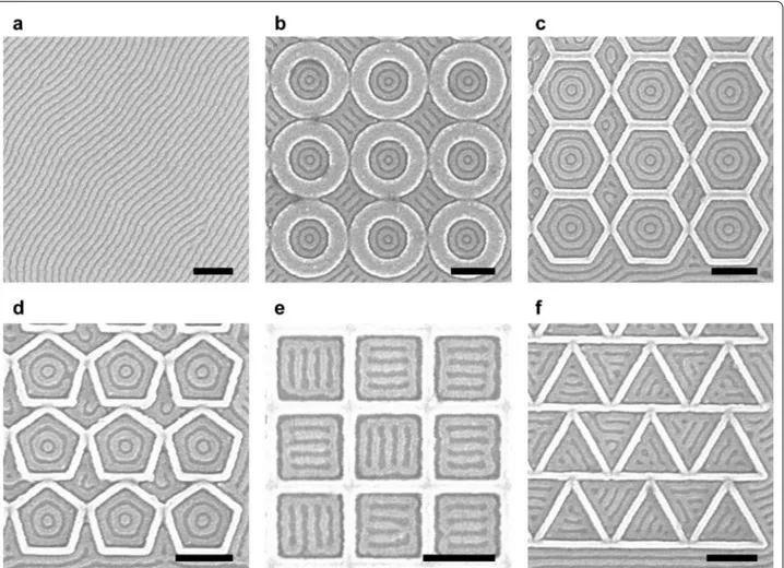
Figure 1 shows an example of oxidized PDMS patterns without any template (Fig. 1a) and within polygonal con-finement (Fig. 1b–f). On an untemplated substrate, the periodicity of the PDMS cylinders (L0) was ~ 36 nm. As shown in Fig. 1b–d, the PDMS cylinders formed a one-state system of concentric rings inside circular, hexago-nal, and pentagonal confinement. However, the PDMS cylinders formed a two-state system inside square finement and a three-state system inside triangular con-finement (Fig. 1e, f). For both confinements, bars parallel to one of the sides were formed inside an outer ring, cre-ating 90° T-junctions for square confinement and 60°
Fig. 1 Scanning electron microscope (SEM) images of untemplated and templated block copolymer patterns. The HSQ templates were
functionalized with the majority PS block. a Untemplated PDMS cylinders with L0 = ~ 36 nm. b One‑state system with concentric rings inside circular confinement. Radius was 2.4L0. c One‑state system inside hexagonal confinement. Apothem was 3.5L0. d One‑state system inside pentagonal confinement. Apothem was 2.5L0. e Two‑state system with degenerate ladder‑shaped structures inside square confinement. Apothem was 2.4L0. f Three‑state system inside triangular confinement. Apothem was 1.8L0. The radius and apothem were measured by subtracting brush thickness from confinement dimensions. Scale bars, 200 nm
Y-junctions for triangular confinement. As the interior angle is decreased, high deformation is imposed on the microdomains at the corners [15, 17], which is relieved by transitioning to a pattern of parallel bars instead of concentric rings. For square confinement, orientation of the parallel bars was restricted to either the horizontal or vertical direction, and these degenerate states are defined as the basis states of the system.
We focus our study on the square confinement since it resulted in a well-defined two-state system with 90° bends and T-junctions. Commensurability is achieved when the width of the confinement minus the brush thickness is equivalent to an integer multiple of L0. Fig-ure 2 shows the ladder-shaped block copolymer patterns formed inside square templates, with the number of par-allel bars increasing with confinement dimensions. The smallest templates produced a one-state system consist-ing of a sconsist-ingle rconsist-ing (Fig. 2a), then a PDMS sphere was formed inside the outer ring as the confinement dimen-sion was increased between 2L0 and 3L0 (Fig. 2b). In this regime, both ladder-shaped structures (two-state sys-tem) and concentric ring structures (one-state syssys-tem) were observed. With increasing dimensions the interior spheres were either horizontally or vertically connected to the outer ring resulting in a two-state system, then an
additional bar was formed inside the outer ring (Fig. 2c– h). For larger incommensurate templates, ladder-shaped structures were still produced, but the number of parallel bars varied by one from structure to structure.
To show that the two basis states are degenerate, we created arrays of 10 by 10 square templates and meas-ured the distribution of horizontally aligned and verti-cally aligned ladder-shaped structures. For simplicity, we defined horizontal alignment as the ‘0’ state and vertical alignment as the ‘1’ state. Among 600 examined struc-tures, 51.5% were in 0 state and 48.5% were in 1 state, forming with essentially equal probability. For a null hypothesis H0: p = 0.5 and alternative hypothesis H1:
p ≠ 0.5 where p denotes ratio of 1 state, the Z-test
sta-tistic was 0.735. The corresponding p-value was 0.462, and we failed to reject the null hypothesis at 5% level of significance. In addition, the binary states had tolerance to defects in the sense that even with defects present the patterns could be assigned as 0 or 1 (Additional file 1: Figure S1a).
Next, we investigated whether the binary state of the four neighbors was correlated with the binary state of the surrounded square. For each square not positioned on the boundary of the square array, there were four adjacent squares as indicated by the red dashed line
Fig. 2 SEM images of ladder‑shaped block copolymer patterns inside square confinement. a, c–h Show commensurate conditions while b shows
transition between a one‑state system (a) and a two‑state system (c) inside incommensurate confinement dimensions. Width of the square confinement was a 2.2L0, b 2.8L0, c 3.0L0, d 4.1L0, e 5.1L0, f 6.1L0, g 7.1L0, and h 8.1L0 (L0 = 36 nm). Depending on the confinement width, 0–6 parallel
Page 4 of 9 Do et al. Nano Convergence (2018) 5:25
(Additional file 1: Figure S1a). The normalized mean state–state correlation is
where sk= +1 for 1 state, sk = −1 for 0 state, and the
sum was taken over every pair of adjacent states. The negligible value of correlation suggests that there is no nearest-neighbor influence.
To investigate the correlation between isolated pairs of adjacent square confinements in samples shown in Addi-tional file 1: Figure S1b, we define nXY as the number of
cases where the left binary state is X (0 or 1) and the right binary state is Y (0 or 1). For 576 structures, the result-ing counts were n00 = 144 (25.0%), n01 = 137 (23.8%),
n10 = 143 (24.8%), and n11 = 149 (25.9%) with 3 (0.5%) defects. The φ coefficient calculated as
was close to zero, indicating negligible association between two adjacent states in isolated pairs of square confinements. A similar set of samples made with a template wall height of 30 nm instead of 42 nm yielded
φ = − 0.03, again indicating negligible association. For
ρ = i∼jsisj i∼j|sisj| = 0.00078 φ =√ n00n11− n01n10 (n00+ n01)(n00+ n10)(n01+ n11)(n10+ n11) = 0.023
wall height below 30 nm, the PDMS cylinders crossed the walls leading to poorly defined block copolymer struc-tures within the templates.
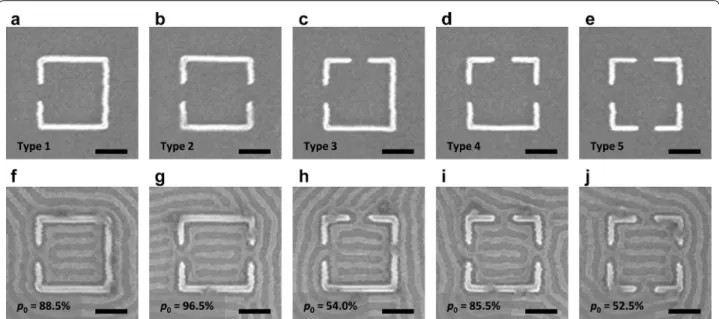
Having established the non-interacting binary-state system described above, we now discuss methods to control the alignment of the states. A simple method for controlling the orientation of the binary states is by creat-ing opencreat-ings in the confinement. Figure 3 shows five pos-sible types of 5L0 wide square confinements with one to four 1L0 wide openings on the sides of the confinement. The fraction of 0 (horizontal cylinders) states was meas-ured for each type of confinement. When there were equal numbers of openings on the top and bottom sides and left and right sides as in type 3 and 5 configurations (Fig. 3c, e), there were equal numbers of 1 and 0 states. However, when there were more openings on the left/ right sides than top/bottom sides as in type 1, 2, and 4 configurations (Fig. 3a, b and d), the 0 state was favored. The highest yield of a preferential alignment was achieved in the type 2 configuration where both openings were in the same direction. When there was one less open-ing in the same direction (type 1) or one more openopen-ing in the other direction (type 4), the yield was decreased by ~ 10%. As the number of openings around the square template was increased, there was less templating effect from the confinement and more defects were formed, but the binary state was still evident (Additional file 1: Figure
Fig. 3 SEM images of square confinement with openings and the resulting block copolymer patterns. Ratio of 0 state (denoted by p0) for each type was measured in a large array. Binary states were determined based on the number of horizontal and vertical openings. a, f Square confinement with one horizontal opening. Preferential horizontal alignment (0 state) was observed. b, g Square confinement with two horizontal openings on non‑adjacent sides. Stronger preferential horizontal alignment was observed. c, h Square confinement with two openings on adjacent sides. Alignment in both directions was observed with equal probability. d, i Square confinement with three openings. Preferential horizontal alignment was observed. e, j Square confinement with four openings. Alignment in both directions was observed with equal probability. These results demonstrate the templating effect from openings. Scale bars, 200 nm
S2). For arrays of square confinements with four open-ings, the normalized mean state–state correlation was
ρ = − 0.00207, suggesting no nearest-neighbor influence
even with openings present between states.
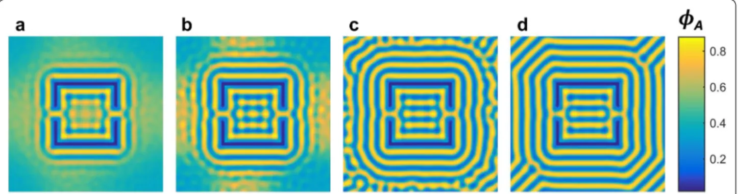
Self-consistent field theory (SCFT) was used to model the effect of a wall opening as a templating method on the final state of the system. We focused on the type 2 template that had the highest preference for one binary state. Although SCFT does not calculate dynamics directly, after several steps order emerges and the model is expected to resemble the evolution of the physical sys-tem. Figure 4a–d show the evolution of the SCFT model starting from a random state. The high attraction at the walls initiated a uniform wetting layer (Fig. 4a) from which an ordering front propagated away from the walls resulting in concentric squares surrounding the template. Two symmetric junctions were formed at the openings in the template walls (Fig. 4b) connecting the inner and outer wetting layers of the template; however, the 1L0 wide openings became blocked isolating the inner poly-mer domains. In addition, the small outward curve of the wetting layer at the openings caused two horizontally aligned polymer domains to form which eventually bridge to create a horizontally disconnected polymer stripe, in remarkable agreement with experiment (Fig. 4c). The presence of this stripe biases the system into the 0 state (Fig. 4d). Additional file 1: Figure S3 shows that the tem-plating effect of the junctions was observed for various simulation conditions (χN and strength of wall prefer-entiality) where the alignment of polymer domains was consistently parallel to the wall openings. On the other hand, the junction connecting the inner and outer wet-ting layers was only stable for low χN and strong wall attraction. This suggests the robustness of this templating
approach to direct the system into a particular state. Based on the strong templating effect from the openings, we expect to observe preferential alignment even when the opening position is changed, as long as the Y-junction is properly formed.
Next, we show that the orientation of the binary states can be also controlled by changing the confinement to a rectangular shape. Figure 5 shows ladder-shaped block copolymer patterns formed inside rectangular confine-ments with an aspect ratio of 2:1. Similar to the square confinement, we were able to accurately control the num-ber of parallel bars using confinement dimensions. When the vertical confinement width was commensurate with
L0, the horizontal confinement width was also commen-surate with L0 since the aspect ratio was an integer. How-ever, we observed only 0 state at these conditions.
When the horizontal and vertical confinement widths are equal to 2nL0 and nL0, respectively, a ladder-shaped structure in the 0 state results in 2n − 4 T-junctions (n is an integer). On the other hand, a ladder-shaped struc-ture in the 1 state results in 4n − 4 T-junctions. Since T-junctions are energetically unfavorable [29–31], the 0 state was favored over the 1 state to minimize the num-ber of T-junctions. The preferential alignment can also be understood as the longer sidewall having a stronger tem-plating effect compared to the shorter sidewall, analogous to the perpendicular orientation of lamellar morphology PS-b-PDMS observed within deep trenches functional-ized with a preferential sidewall brush and a neutral bot-tom surface [32].
In Additional file 1: Figure S4a, the horizontal and vertical dimensions of the confinement were approxi-mately commensurate, 4.1L0 and 2.9L0, respectively, and the structure formed two T-junctions instead of
Fig. 4 SCFT simulations showing the evolution of the polymer self‑assembled pattern. a Early stages of the simulation show a wetting layer
is formed of the inner and outer surface of the walls while the polymer is still disordered in the region surrounding the template. A junction is formed at every opening in the template wall, connecting the inner and outer wetting layers. b An ordering front is propagating away from the walls creating a series of concentric squares. Polymer microdomains are nucleated adjacent to the bends in the inner wetting layer caused by the opening in the walls. c Bridging of the polymer domains creates a horizontal stripe between the two openings. d Final polymer self‑assembled pattern reaches 0 state as shown experimentally
Page 6 of 9 Do et al. Nano Convergence (2018) 5:25
four T-junctions. Non-integer aspect ratios in which only the shorter dimension satisfies the commensurabil-ity condition can also be used to further promote align-ment (Additional file 1: Figure S4b). As the aspect ratio increases, the confinement approximates a trench leading to well-ordered microdomains parallel to the sidewalls.
This approach was extended to fabricate aligned T-junctions with sub-10-nm spacing using a 16 kg/mol cylindrical morphology PS-b-PDMS with L0 = 18 nm, thermally annealed on a functionalized patterned sub-strate. As shown in Fig. 5h, sub-10-nm half-pitch lad-der-shaped structures were formed inside rectangular confinement with the microdomains primarily parallel to the longer side. Unlike SD45, the ladder-shaped struc-tures were influenced by the curvature of the corners of the template due to the smaller L0, and a complete ring was formed between the confinement and the ladder-shaped structure.
Preferential alignment is observed in non-rectangular geometries such as trapezoids and isosceles triangles, as shown in Additional file 1: Figure S5. For trapezoidal confinement, T-junctions formed with desired bending angles because the microdomains aligned parallel to the longer side. Isosceles triangles typically showed preferen-tial alignment parallel to either of the two longer sides. This produced two T-junctions whereas alignment paral-lel to the shorter side resulted in four T-junctions. Thus the confinement geometry determines the number of states, i.e. a three-state system in equilateral triangles (Fig. 1f), a two-state system in acute isosceles triangles or possibly a one-state system in obtuse isosceles triangles.
The third method for controlling the orientation of the binary states is by placing lithographically defined guid-ing patterns inside the confinement. The effect of posts,
dashes, or walls has been previously studied in detail [13,
14, 33]. Additional file 1: Figure S6 shows square confine-ments, each with two horizontal HSQ walls where the walls were positioned a distance L0 away from the edges. Because two PDMS bars in the ladder-shaped block copolymer structures were replaced with the horizontal HSQ walls functionalized with the majority PS block, all block copolymer patterns were also horizontally aligned and set to the 0 state.
Using the three approaches for controlling the binary state orientation, we show how the orientation can be propagated within a larger template array. We showed above that neighboring binary states are uncorrelated with each other in square confinements separated by walls. However, by creating openings in the walls, specific orientations can be programmed by selecting cells from the five types of square confinement. Figure 6 demon-strates two examples of 4 × 4 binary patterns each com-posed of 16 independently controlled binary states. The target patterns are shown in Fig. 6a, d, the templates in Fig. 6b, e, and the successfully produced self-assembled pattern in Fig. 6c, f. For a given target pattern of binary states, in general more than one template can be chosen. To improve yield for larger binary patterns, the second and third templating method can be used to design the template.
Additional file 1: Figure S7 shows examples of differ-ent target patterns and corresponding template designs determined by trial and error. The target patterns shown in Additional file 1: Figure S7a, c are the same as the tar-get patterns shown in Fig. 6a, d. New templates shown in Additional file 1: Figure S7b, d were designed by chang-ing the location of certain openchang-ings and verifychang-ing the result. However, not all target patterns are obtainable by
Fig. 5 SEM images of aligned ladder‑shaped block copolymer patterns inside rectangular confinement. Aspect ratio was 2:1. Vertical width of the
rectangular confinement was a 2.0L0, b 3.1L0, c 4.1L0, d 5.1L0, e 6.1L0, f 7.0L0, and g 7.9L0 for SD45 (L0 = 36 nm). For h, 16 kg/mol PS‑b‑PDMS with
creating openings in the walls, since the opening loca-tions determined by the four neighbors may conflict with the opening locations required for the surrounded square. For example, a target pattern consisting of alter-nating states (Additional file 1: Figure S7k) cannot be obtained from creating openings. By placing guiding pat-terns inside the confinement where such conflict may occur, we are able to design a template that will produce the target pattern (Additional file 1: Figure S7l). In gen-eral, a template for arbitrary binary state pattern can be designed by combining the three templating approaches.
3 Conclusions
The self-assembly of block copolymers inside discrete and interacting polygonal templates is investigated. Square and triangular confinement with dimensions of a few L0 produced ladder-shaped structures instead of the concentric rings seen in smaller confinements or in circular pits. In square confinement, the two degener-ate orientations of the ladder-shaped structures could be
considered as independently controlled binary states with tolerance to defects. The binary states were selected by either creating openings around the confinement, chang-ing the confinement aspect ratio, or placchang-ing additional lithographic features inside the confinement. The result-ing line segments, bends, and T-junctions composresult-ing the ladder-shaped structures may be useful as circuit-rele-vant geometries or binary information storage. Moreo-ver, complex large-area structures can be formed by self-assembly from a sparse template with specific open-ings in the walls that can be written by electron-beam lithography. Although the multi-state composite struc-tures used in our work are less than 1 μm in dimension, we expect larger sizes to yield similar result. If the binary states could be read out optically or electrically in a very large array, the block copolymer patterns could be used to physically store information in addition to functioning as a lithography mask. Future work will involve designing of a two-state system with nearest-neighbor interactions. If an output state can be controlled by lithographically
Fig. 6 Fabrication of binary state arrays. a, d Diagram of desired 4 × 4 binary state arrays. b, e Templates fabricated by electron‑beam lithography. c, f Resulting block copolymer patterns matching the desired binary states. Red indicates 1 state and blue indicates 0 state. Scale bars, 200 nm
Page 8 of 9 Do et al. Nano Convergence (2018) 5:25
defined input states, the two-state system might even be able to perform self-assembly based computation.
4 Methods
4.1 Template fabrication
The topographic templates were fabricated using elec-tron-beam lithography with HSQ resist. A silicon sub-strate was spin coated with 42-nm-thick HSQ film (XR-1541 2% solids, Dow Corning). The thickness was determined by ellipsometry. A Raith 150 electron-beam lithography system operated at 30 kV acceleration volt-age was used to expose topographic features with various geometries. After exposure, the samples were developed in a 24 °C high contrast salty developer (1% NaOH and 4% NaCl in ionized water) for 4 min, rinsed in de-ionized water for 3 min, and blow dried with N2 gas [34]. Template dimensions were inspected by SEM imaging. Templates for 16 kg/mol PS-b-PDMS were fabricated using 30-nm-thick HSQ film.
4.2 Block copolymer self‑assembly
To make the templates attractive to the majority PS block, the templates were chemically functionalized with a hydroxyl-terminated PS brush (11 kg/mol, Poly-mer Source Inc.) by spin coating 1% brush solution in propylene glycol monomethyl ether acetate (PGMEA) and annealing the samples in a vacuum oven at 170 °C for 14 h. The samples were rinsed with toluene for 1 min after annealing to remove excess PS brush. The result-ing thickness of the PS brush bonded to the substrate was 5 nm. Next, 2% PS-b-PDMS (Mw = 45.5 kg/mol,
fPDMS = 32%, PDI = 1.08, Polymer Source Inc.) solution in PGMEA was spin coated onto the templated substrate. The resulting film thickness was 27 nm. The samples were solvent annealed using a 5:1 mixture of toluene and heptane at room temperature for 5 h. We placed the sam-ples on a glass slide stack (0.8 cm in height) inside a crys-tallization dish (1.5 cm in height, 5 cm in diameter) and added 1.5 ml of the 5:1 toluene and heptane mixture. The chamber was covered with a petri dish (10 cm in diam-eter). During the 5 h annealing, leakage of solvent vapor occurred at a rate of 585 µg/min. 16 kg/mol PS-b-PDMS (fPDMS = 31%, PDI = 1.08, Polymer Source Inc.) was spin coated to a thickness of 25 nm and thermally annealed in a vacuum oven at 150 °C for 14 h.
4.3 Reactive‑ion etching
Reactive-ion etching of the annealed block copolymer film was performed in two steps. First, the top PDMS wetting layer was removed using a 5 s CF4 plasma treat-ment with a power of 50 W and pressure of 15 mTorr. Next, the PS matrix was removed using a 22 s O2 plasma treatment with a power of 90 W and pressure of 6 mTorr.
This step also oxidized the PDMS cylinders. For 16 kg/ mol PS-b-PDMS, the CF4 plasma was applied for 3 s and O2 plasma was applied for 12 s.
4.4 Metrology
Metrology was performed by examining the HSQ tem-plates and the reactive-ion etched block copolymer films using a SEM. Top down SEM images were obtained using a Raith 150 SEM operated at 10 kV acceleration volt-age and 6 mm working distance, and Zeiss Sigma SEM operated at 3 kV acceleration voltage and 4 mm working distance.
4.5 Simulation details
Simulation details are provided in the additional file.
Additional file
Additional file 1. Additional Figures S1–S7 and Simulation Details.
Abbreviations
DSA: directed self‑assembly; PS‑b‑PDMS: poly(styrene‑block‑dimethylsiloxane); SD45: 45 kg/mol PS‑b‑PDMS; HSQ: hydrogen silsesquioxane; SEM: scanning electron microscope; SCFT: self‑consistent field theory; PGMEA: propylene glycol monomethyl ether acetate.
Authors’ contributions
HWD and HKC contributed equally to this work. All authors have contributed to the writing of the manuscript. All authors read and approved the final manuscript.
Author details
1 Department of Electrical Engineering and Computer Science, Massachusetts
Institute of Technology, Cambridge, MA 02139, USA. 2 Department of Chemi‑
cal and Biomolecular Engineering, Korea Advanced Institute of Science and Technology, Daejeon, South Korea. 3 Department of Materials Science
and Engineering, Massachusetts Institute of Technology, Cambridge, MA 02139, USA. 4 Division of Advanced Materials Engineering, Kongju National
University, Cheonan, South Korea. 5 Department of Biomedical Engineering,
Sungkyunkwan University, Seoul, South Korea.
Acknowledgements
The authors would like to thank J. M. Daley and M. K. Mondol for technical assistance, and S. M. Nicaise, A. Tavakkoli K. G., and W. Bai for helpful discus‑ sions. MIT’s Scanning‑Electron‑Beam Lithography facility at the Research Laboratory of Electronics (SEBL at RLE) provided facilities for this study.
Competing interests
The authors declare that they have no competing interests.
Availability of data and materials
The datasets supporting the conclusions of this article are included within the article and its additional file.
Funding
This study was supported by National Science Foundation (Award No. CMMI‑ 1234169) and Taiwan Semiconductor Manufacturing Company.
Publisher’s Note
Springer Nature remains neutral with regard to jurisdictional claims in pub‑ lished maps and institutional affiliations.
Received: 14 May 2018 Accepted: 5 September 2018
References
1. H. Uehara, M. Kakiage, M. Sekiya, D. Sakuma, T. Yamonobe, N. Takano, A. Barraud, E. Meurville, P. Ryser, ACS Nano 3, 4 (2009). https ://doi. org/10.1021/nn800 8728
2. W.A. Phillip, B. O’Neill, M. Rodwogin, M.A. Hillmyer, E.L. Cussler, A.C.S. Appl, Mater. Interfaces 2, 3 (2010). https ://doi.org/10.1021/am900 882t
3. C. Hägglund, G. Zeltzer, R. Ruiz, I. Thomann, H.‑B.‑R. Lee, M.L. Brongersma, S.F. Bent, Nano Lett. 13, 7 (2013). https ://doi.org/10.1021/nl401 641v
4. S.K. Cha, J.H. Mun, T. Chang, S.Y. Kim, J.Y. Kim, H.M. Jin, J.Y. Lee, J. Shin, K.H. Kim, S.O. Kim, ACS Nano 9, 5 (2015). https ://doi.org/10.1021/acsna no.5b016 41
5. H. Yi, X.‑Y. Bao, J. Zhang, C. Bencher, L.‑W. Chang, X. Chen, R. Tiberio, J. Conway, H. Dai, Y. Chen, S. Mitra, H.‑S.P. Wong, Adv. Mater. 24, 23 (2012).
https ://doi.org/10.1002/adma.20120 0265
6. H. Yi, X.‑Y. Bao, R. Tiberio, H.‑S.P. Wong, Nano Lett. 15, 2 (2015). https ://doi. org/10.1021/nl502 172m
7. H. Tsai, J.W. Pitera, H. Miyazoe, S. Bangsaruntip, S.U. Engelmann, C.‑C. Liu, J.Y. Cheng, J.J. Bucchignano, D.P. Klaus, E.A. Joseph, D.P. Sanders, M.E. Col‑ burn, M.A. Guillorn, ACS Nano 8, 5 (2014). https ://doi.org/10.1021/nn501 300b
8. X. Yang, L. Wan, S. Xiao, Y. Xu, D.K. Weller, ACS Nano 3, 7 (2009). https ://doi. org/10.1021/nn900 073r
9. O. Hellwig, J.K. Bosworth, E. Dobisz, D. Kercher, T. Hauet, G. Zeltzer, J.D. Risner‑Jamtgaard, D. Yaney, R. Ruiz, Appl. Phys. Lett. 96, 5 (2010). https :// doi.org/10.1063/1.32933 01
10. R. Ruiz, E. Dobisz, T.R. Albrecht, ACS Nano 5, 1 (2011). https ://doi. org/10.1021/nn101 561p
11. C.T. Black, O. Bezencenet, IEEE Trans. Nanotechnol. 3, 3 (2004). https :// ieeex plore .ieee.org/docum ent/13313 32/. Accessed 12 Sept 2018 12. T. Yamaguchi, H. Yamaguchi, Adv. Mater. 20, 9 (2008). https ://doi.
org/10.1002/adma.20070 2546
13. J.K.W. Yang, Y.S. Jung, J.‑B. Chang, R.A. Mickiewicz, A. Alexander‑Katz, C.A. Ross, K.K. Berggren, Nat. Nanotechnol. 5 (2010). https ://www.natur e.com/ artic les/nnano .2010.30
14. J.‑B. Chang, H.K. Choi, A.F. Hannon, A. Alexander‑Katz, C.A. Ross, K.K. Berg‑ gren, Nat. Commun. 5, 3305 (2014). https ://www.natur e.com/artic les/ ncomm s4305 . Accessed 12 Sept 2018
15. G.M. Wilmes, D.A. Durkee, N.P. Balsara, J.A. Liddle, Macromolecules 39, 7 (2006). https ://doi.org/10.1021/ma052 6443
16. J.Y. Cheng, C.T. Rettner, D.P. Sanders, H.‑C. Kim, W.D. Hinsberg, Adv. Mater.
20, 16 (2008). https ://doi.org/10.1002/adma.20080 0826
17. M.P. Stoykovich, M. Müller, S.O. Kim, H.H. Solak, E.W. Edwards, J.J. de Pablo, P.F. Nealey, Science 308, 5727 (2005). http://scien ce.scien cemag .org/ conte nt/308/5727/1442. Accessed 12 Sept 2018
18. M.P. Stoykovich, H. Kang, K.C. Daoulas, G. Liu, C.‑C. Liu, J.J. de Pablo, M. Müller, P.F. Nealey, ACS Nano 1, 3 (2007). https ://doi.org/10.1021/nn700 164p
19. G. Liu, C.S. Thomas, G.S.W. Craig, P.F. Nealey, Adv. Funct. Mater. 20, 8 (2010).
https ://doi.org/10.1002/adfm.20090 2229
20. Y.S. Jung, W. Jung, C.A. Ross, Nano Lett. 8, 9 (2008). https ://doi. org/10.1021/nl802 011w
21. S.‑J. Jeong, J.E. Kim, H.‑S. Moon, B.H. Kim, S.M. Kim, J.B. Kim, S.O. Kim, Nano Lett. 9, 6 (2009). https ://doi.org/10.1021/nl900 4833
22. J. Chai, D. Wang, X. Fan, J.M. Buriak, Nat. Nanotechnol. 2 (2007). https :// www.natur e.com/artic les/nnano .2007.227. Accessed 12 Sept 2018 23. J.G. Son, M. Son, K.‑J. Moon, B.H. Lee, J.‑M. Myoung, M.S. Strano, M.‑H.
Ham, C.A. Ross, Adv. Mater. 25, 34 (2013). https ://doi.org/10.1002/ adma.20130 0813
24. A. Nourbakhsh, A. Zubair, R.N. Sajjad, K.G. Tavakkoli, W. Chen, S. Fang, X. Ling, J. Kong, M.S. Dresselhaus, E. Kaxiras, K.K. Berggren, D. Antoniadis, T. Palacios, Nano Lett. 16, 12 (2016). https ://doi.org/10.1021/acs.nanol ett.6b039 99
25. Y.S. Jung, C.A. Ross, Nano Lett. 7, 7 (2007). https ://doi.org/10.1021/nl070 924l
26. R. Ruiz, N. Ruiz, Y. Zhang, R.K. Sandstrom, C.T. Black, Adv. Mater. 19, 16 (2007). https ://doi.org/10.1002/adma.20060 2470
27. E. Han, H. Kang, C.‑C. Liu, P.F. Nealey, P. Gopalan, Adv. Mater. 22, 38 (2010).
https ://doi.org/10.1002/adma.20100 1669
28. H.K. Choi, J.‑B. Chang, A.F. Hannon, J.K.W. Yang, K.K. Berggren, A. Alexander‑Katz, C.A. Ross, Nano Futures 1, 1 (2017). https ://doi. org/10.1088/2399‑1984/aa641 c
29. S.P. Gido, E.L. Thomas, Macromolecules 27, 21 (1994). https ://doi. org/10.1021/ma000 99a03 1
30. E. Burgaz, S.P. Gido, Macromolecules 33, 23 (2000). https ://doi. org/10.1021/ma000 729s
31. D. Duque, K. Katsov, M. Schick, J. Chem. Phys. 117, 22 (2002). https ://doi. org/10.1063/1.15195 37
32. W. Bai, K. Gadelrab, A. Alexander‑Katz, C.A. Ross, Nano Lett. 15, 10 (2015).
https ://doi.org/10.1021/acs.nanol ett.5b028 15
33. A.F. Hannon, Y. Ding, W. Bai, C.A. Ross, A. Alexander‑Katz, Nano Lett. 14, 1 (2014). https ://doi.org/10.1021/nl404 067s
34. J.K.W. Yang, K.K. Berggren, J. Vac. Sci. Technol. B 25, 6 (2007). https ://doi. org/10.1116/1.28018 81