HAL Id: hal-01129316
https://hal.archives-ouvertes.fr/hal-01129316
Submitted on 22 Sep 2015
HAL is a multi-disciplinary open access
archive for the deposit and dissemination of
sci-entific research documents, whether they are
pub-lished or not. The documents may come from
teaching and research institutions in France or
abroad, or from public or private research centers.
L’archive ouverte pluridisciplinaire HAL, est
destinée au dépôt et à la diffusion de documents
scientifiques de niveau recherche, publiés ou non,
émanant des établissements d’enseignement et de
recherche français ou étrangers, des laboratoires
publics ou privés.
Exploiting Parallelism in FPGAs for the Real-Time
Interpretation of Interactive Multimedia Scores
Jaime Arias, Myriam Desainte-Catherine, Camilo Rueda
To cite this version:
Jaime Arias, Myriam Desainte-Catherine, Camilo Rueda. Exploiting Parallelism in FPGAs for the
Real-Time Interpretation of Interactive Multimedia Scores. Journées d’Informatique Musicale 2015,
May 2015, Montréal, Canada. �hal-01129316�
EXPLOITING PARALLELISM IN FPGAS FOR THE REAL-TIME
INTERPRETATION OF INTERACTIVE MULTIMEDIA SCORES
Jaime Arias, Myriam Desainte-Catherine
Univ. Bordeaux, LaBRI, CNRS UMR 5800
F-33400 Talence, France
{jaime.arias, myriam}@labri.fr
Camilo Rueda
DECC, Pontificia Universidad Javeriana
Cali, Colombia
[email protected]
RÉSUMÉ
La performance est essentielle pour les applications in-teractives multimédia. Cependant, la plupart de ces applica-tions sont séquentielles ou sont exécutées sur des systèmes d’exploitation qui fournissent une latence qui ne convient pas pour la performance temps réel. Dans cet article, nous présentons une solution à ce problème, dans le cas parti-culier de l’interprétation des partitions multimédia interac-tives. Il s’agit d’une nouvelle implémentation parallèle des partitions interactives sur du matériel reconfigurable. Nous tirons parti du parallélisme et de la fiabilité des Field Pro-grammable Gate Arrays (FPGAs) pour exécuter en temps réel une représentation matérielle des partitions. Le résultat des simulations montre que notre approche permet au sys-tème de réagir instantanément aux interactions de l’utilisateur. De plus, les contraintes temps réel de la partition sont satis-faites.
ABSTRACT
Real-time performance is essential for interactive multi-media applications. However, most of these applications are sequential or they are executed on architectures and operat-ing systems that do not provide a low-latency real-time per-formance. In this paper, we present a solution to this prob-lem, specifically in the interpretation of interactive multime-dia scores. For that, we present a novel parallel implementa-tion of interactive scores on a reconfigurable hardware. We take advantage of the parallelism and reliability provided by Field Programmable Gate Arrays (FPGAS) to perform in real-time the hardware representation of scores. The results of the simulations show that our approach allows the system to react instantaneously to user interactions. Moreover, the real-time constraints of the score are satisfied.
1. INTRODUCTION
The performance of standard computers is not sufficient for some multimedia applications that perform compute-intensive, data-intensive and real-time tasks. The idea of perform-ing these applications on supercomputers is often
unfeasi-ble since they are extremely expensive. However, the use of Field Programmable Gate Arrays (FPGAs) is a reasonable price alternative to achieve the performance level needed for multimedia applications.
Interactive Scores (IS) [1, 9] is a formalism for compos-ing and interpretcompos-ing interactive multimedia scenarios. Sce-narios are composed of two kind of temporal objects (TOs): texturesand structures. Textures represent the execution of multimedia processes. Structures allow to design modular scenarios and impose a hierarchical organisation on them. The temporal organisation of TOs is defined by asserting temporal relations (TRs) those objects should obey. In IS, the performer can influence the execution of the scenario by triggering interactive points (IPs). They are used to modify the start/stop times of the TOs during execution. An im-portant requirement of this model is that the temporal con-straints defined by the composer must be preserved during the execution of the score. Nowadays, IS has a wide range of applications such as video games, live performance and virtual museum installations [2].
Currently, the softwareI-SCORE[16] implements the model described above. It consists of two stages: composition and execution. During composition stage, the composer places boxes representing TOs on a horizontal time-line and de-fines TRs (constraints) between them. At execution stage, the written score is first translated into a Hierarchical Time Stream Petri Net (HTSPN) [20] that is then interpreted by an abstract machine. The execution model is implemented using threads which make the implementation very nonde-terministic and unreliable [14]. Moreover,I-SCORE is not designed for real-time operating systems or parallel com-puter architectures. Thus, the low-latency and real-time per-formance of interactive scores is not guaranteed.
In this paper, we present a novel parallel and flexible im-plementation of the execution model of IS on a reconfig-urable hardware. The use of FPGAs aims to overcome the current performance problems ofI-SCOREby taking advan-tage of the low-latency, parallelism and high-reliability of these devices. Moreover, FPGAs are synchronous hardware with a jitter less than one cycle of clock and they also are not affected by the rather complex behaviour of the operating
system services, interrupt handling, etc. Due to the physical parallelism, the processes do not influence each other.
In our approach, a scenario is viewed as a synchronous system [8] in which TRs and TOs are deterministic pro-cesses that are executing in parallel. The start and stop dates of the processes depend on the events emitted by the other processes [4]. The most basic module of our implementa-tion is a process that models a TR. Thanks to its determinis-tic behaviour, it can be represented as a Finite State Machine (FSM). As we shall see, any score written inI-SCOREcan be represented as a finite set of these processes running in parallel. Our approach is generic and device-independent since we use SystemVerilog (a high-level hardware descrip-tion language) [21] to implement it. Therefore, a score is compiled into our generic model in SystemVerilog that can be synthesised on different FPGAs. The results of the simu-lations show that our approach allows to satisfy all real-time constraints imposed by the composer and also that it pro-vides a low-rate data synchronisation that allows to satisfac-tory react to the stimulus sent by the environment.
The rest of the paper is organised as follows. In Section 2 we briefly introduce FPGAs. Next, in Section 3 we present the IS model and its current implementation inI-SCORE. In Section 4 we present the hardware implementation of IS and some simulations in order to better understand our approach. We conclude in Section 5 by pointing out to related work and discussing on some ideas for future work.
2. OVERVIEW OF FIELD PROGRAMMABLE GATE ARRAYS (FPGAs)
A Field Programmable Gate Array (FPGA) is a digital inte-grated circuit (IC) that can be reprogrammed, many times, to desired functionality requirements after manufacturing. This feature distinguishes them from the Application Spe-cific Integrated Circuits (ASICS) which are manufactured for specific tasks. FPGAs provide huge power, area, and performance benefits over software. They can simultane-ously compute millions of operations in resources distributed on the device (i.e., spatial computing). Then, such systems can be hundred of time faster than microprocessors-based systems. FPGAs have already been used with success in many different industrial applications (e.g., aerospace, auto-motive, medical, video and audio processing applications) [11, 17–19].
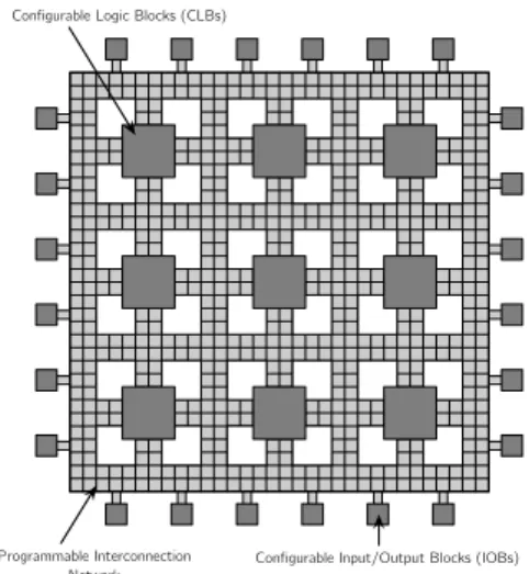
The general architecture of an FPGA is defined as a ma-trix of configurable logic blocks (CLBS). Moreover, this matrix is surrounded by a ring of configurable input/output blocks (IOBS). All of these resources are linked to each
other by an interconnection network which is highly flexi-ble and reprogrammaflexi-ble (see Figure 1). Additionally, some FPGAs provide dedicated blocks such as DSP accelerators and embedded hard processors cores (e.g., ARM CORTEX -A9).
Configurable Logic Blocks (CLBs)
Programmable Interconnection
Network Configurable Input/Output Blocks (IOBs) Figure 1. Generic architecture of an FPGA.
A CLB is the basic logic unit of an FPGA and its num-ber varies from device to device. It consists of two, four or more logic cells containing processing elements for per-forming simple combinational and sequential logic. In gen-eral, a logic cell is composed of a 4-input Look-Up Table (LUT) and a D-Type Flip Flop (see Figure 2).
D Q Q Look-up Table (LUT) Flip Flop Mux Clock I0 I1 I2 I3 Out
Figure 2. A logic cell.
FPGAs have risen over the last years and at the same time their costs. As a result, they have become economically viable for use in several applications. Moreover, they offer the following benefits [10]:
• Reconfigurability: FPGAs can be reconfigured at any time.
• High-level design: The hardware is defined by us-ing high-level hardware description languages (e.g., VHDL and SystemVerilog). Moreover, the designed systems can be simulated and verified before their ex-ecution on the FPGA.
• Physical Parallelism: FPGAs allow to design com-pletely parallel systems without computation loading. • High-speed: Parallelism and fast clock rates of FPGAs
allow systems to achieve very high speed that some-times outperforms processor-based systems.
• Reliability: FPGAs provide true hardware reliability because there is no operating system or driver layer that can affect system update.
• IP protection and re-use: It is difficult to reverse en-gineering a synthesised system. Moreover, a tested hardware design can be re-used multiple times by in-stantiating.
The creation of an FPGA-based system consists on build-ing a bitstream file to load into the device. The designers start with an application written in a hardware description language (HDL), such as SystemVerilog or VHDL. This abstract design is optimised to fit into the FPGA’s avail-able logic. Next, the optimised design is mapped into logic blocks and routing determines the interconnected resources. Finally, the bitstream file is generated in order to properly configure the logic blocks and routing resources of the FPGA. Once the bitstream file is loaded into the FPGA, it operates as a custom digital system.
3. OVERVIEW OF INTERACTIVE SCORES
Interactive Scores (IS) [1, 9] is a formalism for composing and interpreting interactive multimedia scores (e.g., living arts) in which the performer has the possibility to influence the execution of the score. Roughly, the composer partially defines the hierarchical and the temporal organisation of the score by means of temporal relations (TRs) between tem-poral objects (e.g., multimedia processes). In addition, the composer allows the performer to modify, during execution, the starting and ending dates of the temporal objects (TOs) by adding interaction points (IPs). In that sense, the per-former enjoys a certain freedom in triggering dynamically IPs during performance while the system assures the consis-tency of the temporal relations of the score. Thus, a perfor-mance constitutes an instance of a set of possible scenarios that share the same temporal properties.
As mentioned above, composers define the temporal or-ganisation of their scores by adding temporal relations be-tween temporal objects. TOs are classified into two types: textures and structures. Textures represent the execution in time of a given multimedia process (e.g., changing the brightness of a light) while structures (i.e., the hierarchical organisation of the score) represent only the execution of a group of TOs with their own temporal organisation. In this regard, a score is represented as a structure that con-tains the temporal organisation of the TOs placed by the composer. It is important to note that multimedia processes are executed by external applications such as MAX/MSP1
or PURE DATA2. Each TO has associated a set of control points that represent particular moments of its execution, for
1http://cycling74.com 2http://puredata.info
example, the start and the end. The possibilities of interac-tion are expressed by means of IPs that turn a control point into a dynamic one. Dynamic control points must be explic-itly triggered by the performer during the execution while the other control points (the static control points) are trig-gered by the system.
With respect to TRs, there are two qualitative relations that are defined between control points: precedence and pos-teriority. These relations are taken from point algebra and they are symmetrical. Moreover, TRs are enhanced with quantitative constraints by giving a range of possible du-rations in [0, ∞]. Thus, the composer must define a min-imum duration (∆min) and a maximum duration (∆max)
for each TR. Depending on the above values, TRs can be classified as: (1) rigid, if ∆min = ∆max > 0; (2)
synchro-nisation, if ∆min = ∆max = 0; (3) flexible or supple, if
∆min = 0 and ∆max = ∞; and (4) flexible or
semi-rigid, if ∆max6= ∞ and ∆min6= ∆max.
Currently, the model described above is implemented in the software called I-SCORE3. This software consists of two different stages: composition and performance. Dur-ing composition stage, composers place TOs, represented as boxes, on a horizontal time-line. Then, they add IPs and connect TRs between the TOs in order to define temporal properties on their scores.
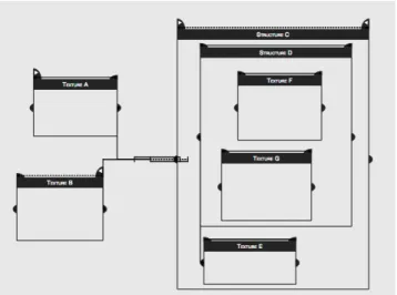
For example, Figure 3 shows a score composed inI-SCORE
with seven boxes: A, B, E, F and G are textures whereas Cand D are structures. The solid/dashed arrows represent semi-flexible relations. Note that boxes A, B and C have IPs which are represented as flags. Additionally, the start date of each TO (except C and E) is defined by an implicit temporal relation from the starting of its parent.
Figure 3. Example of an interactive score. A, B, E, F , G are textures whereas C and D are structures.
Since during composition stage the computation time is
not critic, the score is viewed as a Constraint Satisfaction Problem (CSP) in order to maintain its temporal organisa-tion. Thus, when the composer changes the characteristics of a TO (i.e., the start date and duration), a general con-straint solver, in this case GECODE4, propagates the new constraints, which leads the TOs to automatically move or stretch in order to keep the temporal properties imposed by the composer.
On the other side, during execution the performer can dy-namically trigger the IPs while the static control points are triggered by the system. As mentioned above, multimedia processes are executed by external applications, thereforeI
-SCORE uses multimedia protocols like OSC5 in order to send the messages defined by the composer when textures start and end. Additionally, IPs are also triggered by specific messages that are sent asynchronously during performance by the performer. It is important to note that the system will refuse an IP triggered outside of the range of time defined by the composer. Moreover, the system will automatically trigger the IP when the maximum time has elapsed and the performer has not triggered it. In this way, the system main-tains the temporal properties imposed by the composer. The following example illustrates the interpretation of an inter-active score. Moreover, it will be used in Section 4 in order to better understand and validate our approach.
Example 1. Assume the interactive score in Figure 3 with the following temporal organisation:
• Texture A has a duration of 3 ms and it starts at 5 ms. The performer can anticipate the starting of this box until 3 ms before of its start time.
• Texture B has a duration of 6 ms and it starts at 8 ms. The performer can stop this box after 3 ms of its starting.
• Texture F has a duration of 4 ms and it starts after 4 ms of starting the structure D.
• Texture G has a duration of 10 ms and it starts after 1 ms of starting the structure D.
• Texture E has a duration of 6 ms and its starting is synchronised with the starting of structure D. • Structure D has a duration of 14 ms and it starts after
2 ms of starting structure C. It contains the textures F and G.
• Structure C has a duration of 20 ms, but the performer can stop it after 4 ms of its starting. It starts after 20 ms and 10 ms of stopping the texture A and B, respectively. The performer can anticipate its starting after 7 ms and 5 ms of stopping the textures A and B,
4http://www.gecode.org
5http://opensoundcontrol.org/introduction-osc
respectively. This structure contains the structure D and texture E.
• The score finishes when the structure C has finished.
In order to execute the written scores, an abstract ma-chine, called ECO mama-chine, is used [16]. This machine is responsible of (1) triggering the static control points; (2) controlling, in real-time, the triggering of the dynamic con-trol points; and (3) maintaining the temporal organisation of the score. The operation of the machine is described in terms of state transitions that are synchronised with a global clock. Each state is composed of three components: Envi-ronment, Controls and Outputs. Roughly, the Environment component contains all temporal and data information, rep-resented as a Petri Net, needed to produce the outputs; the Controls component handles the messages that trigger the dynamic control points; and the Outputs component repre-sents the part of the machine that receives messages from the Petri net and sends the data produced by processes through the output flow.
Since this machine is generic, it will be strictly the same for each score except its Environment component which de-pends on the score. Therefore, each time an interactive score is written or modified, it must be translated into a Hierarchi-cal Time Stream Petri Net (HTSPN) [20] in order to rep-resent and execute the partially ordered set of events (i.e., the start and end of TOs). The method to transform a score into a HTSPN is the following [16]: each control point is turned into a transition. If a temporal constraint imposes the simultaneity of different control points, their transitions are merged. If a precedence relation is specified between two control points, a sequence arc/place/arc is added between the transitions that represent them. The range of time that represents the duration of a TR is defined over each arc and it represents the possible durations of the relation. Further-more, the firing of a transition that represents a dynamic control point is conditioned by receiving an external con-trol message. It is important to note that each ingoing arc of this kind of transition has minimum and maximum duration values that correspond with the time range decided by the compositor. The minimum value corresponds to the mini-mum time at which we can cross the transition whereas the maximum value corresponds to the time at which the transi-tion will be crossed if the message has not been sent before. In closing, an important characteristic of the IS model is that it mixes two temporal paradigms used in the current multimedia tools [9]: time-line and time-flow. The time-line paradigm is represented by the composition stage because the composer places multimedia processes with their start and end dates, as well as temporal relations between them. On the other hand, the time-flow paradigm is represented by the execution stage at which the processes are executed while the temporal relations are preserved.
Figure 4. Obtaining a clock of 2.5 MHz from a clock of 50 MHz.
4. A TRUE PARALLEL IMPLEMENTATION OF INTERACTIVE SCORES
In this section, we present the hardware implementation of interactive scores. Before that, let us introduce a mechanism to generate the global clock of the score. Our main objective is to execute the score on an FPGA which provides a stable clock on the order of nanoseconds (ns). Then, it is appro-priated to generate our own clock for the score in order to facilitate the handling of time. The following equation al-lows to know the number of clock cycles needed to obtain an intended clock.
#cycles = period_clock_score
period_clock_F P GA (1) The following example shows how to generate a clock signal.
Example 2. Assume that we need to generate a clock of 2.5 MHz (i.e., a period of 400 ns) from a clock of 50 MHz (i.e., a period of 10 ns). Applying (1), we obtain that a clock cycle of 2.5 MHz is equivalent to 20 cycles of 50 MHz. We illustrate this result in Figure 4.
Figure 5 shows the block diagram of our clock generator. It takes a clock signal as an input and generates a new clock signal by dividing the original signal by a specific number of cycles. This module will be useful for implementing TRs and TOs. FPGA_Clock Cycles Reset Score_Clock Global clock score
Figure 5. Block diagram of the clock generator.
4.1. Temporal Relations
In our approach, a TR imposes both a precedence and a tem-poral relation between two points that are placed on a time-line. In that sense, a TO is modelled as two points denoting
its starting and its stopping, and a TR between them to de-note its duration. Moreover, a relation between two TOs is represented as a TR between two points of different TOs. In the following, we will show how to represent in hardware a complete score using this simple model based on TRs.
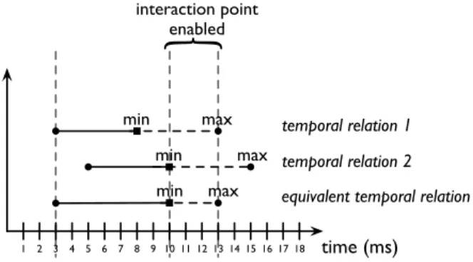
Intuitively, a TR is a synchronous process that starts im-mediately it receives a specific event. Once this occurs, it waits for the elapsing of its duration, and then it emits an event to notify that it has finished. An IP is represented as an external event that is asynchronously sent by the environ-ment (i.e., the performer or other processes). TRs can be stopped if they receive an event denoting an IP. We recall that IPs stop the execution of a TR if they arrive within the temporal interval specified by the composer. Let us show a simple example on how the TRs and IPs allow to represent a complex behaviour on a score. Consider two TRs and an IP defining the start date of a TO. Both TRs have a mini-mum duration of 5 ms and a maximini-mum duration of 10 ms. However, the first one starts at 3 ms while the second at 5 ms. Therefore, the time interval at which the IP can be trig-gered is [10,13] ms. As we can see in Figure 6, within this time interval the temporal constraint defined by both TRs is satisfied. Moreover, the TO will start at 13 ms if the IP is not triggered before. To simplify notation, we shall write the duration of a TR as [min, max] where min denotes its minimum duration and max denotes its maximum duration.
temporal relation 1 temporal relation 2 equivalent temporal relation
min max min max min max interaction point enabled time (ms) 1 2 3 4 5 6 7 8 9 10 11 12 13 14 15 16 17 18
Figure 6. Interpretation of TRs and IPs.
The deterministic behaviour of TRs allows to represent them as a Finite State Machine (FSM). A Mealy FSM ade-quately express the behaviour of synchronous systems since
(1) the outputs depend on both the current state and the in-puts; and (2) the outputs react instantaneously to the inputs. Figure 7 shows the block diagram of a TR. In our approach, we use two timers to handle the minimum and the maxi-mum duration of the TR. Additionally, we use a FSM to control the states of the TR. The clock of both timers is the same as the score whereas the clock of the FPGA is used for the FSM. This is very important because the FSM must be much faster than the smallest time unit of the score.
In the following, we describe each state of the FSM and its interaction with the environment and the timers. Since we shall use TRs to represent TOs, each state moves to the state STOPand emits an event to stop other TOs when a kill event (that will be sent by its parent) is received. Moreover, the FSM emits a kill signal when the TR stops (i.e., there is a transition to the state STOPfrom the state WAIT MIN
or WAIT END) in order to kill its possible children. For instance, when a TR representing a structure is stopped by an IP.
• IDLE: It is the initial state. It disables the timers by setting their reset and enable inputs to 0. Its purpose is to wait for the start of the TR. Thus, it goes to the state NEWwhen it receives the start event.
• NEW: It initialises the first timer with the minimum duration of the TR and the second with its maximum duration. After that, it moves to the state WAITMIN. • WAITMIN: It enables both timers in order to start the countdown to 0. In this state, the FSM has the following alternatives: (1) the minimum duration has elapsed (i.e., timeout of the first timer), then it moves to the state WAIT END; (2) the maximum duration has elapsed (i.e., timeout of the second timer), then it emits the stop and kill events and goes to the state STOP; or (3) a new temporal relation has started (i.e., it receives a start signal), then it passes to the state ADD. Let us explain a little the meaning of each al-ternative.
The alternative (1) implies that the minimum duration has elapsed and now it is necessary to wait for either the maximum duration or the triggering of an IP (state WAIT END). The alternative (2) says that the mini-mum and maximini-mum duration are the same, thus the TR must stop (state STOP). Lastly, the alternative (3) expresses the situation presented in Figure 6 in which the composer uses several TRs to define a temporal constraint. Therefore, it is necessary to compute the new duration of the TR (state ADD), since the start time and the duration of the new TR can be different. • ADD: It resets the timers to the following values. The first timer, representing the minimum duration, is re-set to the maximum value between the remaining time
of the timer and the minimum duration of the TR that has just started. The second timer, representing the maximum duration, is reset to the minimum value be-tween the remaining time of the timer and the max-imum duration of the new TR. Once this occurs, it moves to the state WAITMIN.
Let us show a simple example to better understand our idea. Assume the scenario illustrated in Figure 6 in which a TR with a duration of [5,10] ms has started at 3 ms. At 5 ms, the first timer has a value of 3 and the second timer has a value of 8. Now, we consider that a new TR with duration [5,10] ms starts at 5 ms. Then, the first timer is reset to 5 and the second timer is reset to 8. Hence, the minimum duration of the resulting TR will elapse at 10 ms and it will stop at 13 ms. The resulting TR then satisfies the temporal constraint defined by the composer.
• WAITEND: This state waits for either the elapsing of the maximum duration or the triggering of an external event. When this occurs, it emits the stop event and goes to the state STOP.
• STOP: It is the final state. It disables the timers. Let us now present an example illustrating the execution of our hardware implementation.
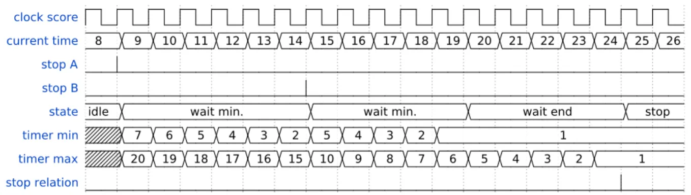
Example 3. Consider the score in Figure 3. Textures A and B stop at 8 ms and at 14 ms, respectively. Moreover, the TR between the texture A and the structure C has a duration of [7,20] ms, and the TR between the texture B and the struc-ture C has a duration of [5,10] ms. As we saw before, the time interval at which the structure C can start is [19,24] ms. We show the simulation of the above scenario in Figure 8. Observe that at 8 ms the texture A stops then, the timers are reset to the values 7 (timer 1) and 20 (timer 2). After 6 ms (i.e., at 14 ms), the texture B stops and the timers are reset to 5 (timer 1) and 10 (timer 2) by applying the operations described above. After 5 ms (i.e., at 19 ms), the minimum duration elapses and the FSM begins to wait for either the elapsing of the maximum duration or the triggering of an IP. At 14 ms, the TR stops because the maximum duration elapses and the IP was not triggered.
IPs are represented as asynchronous events that are trig-gered during execution by the user or other processes (e.g., an OSC server). We then synchronise these events and the outputs of the FSM with the clock of the score. In this way, we maintain synchronous our system. The following exam-ple illustrates the triggering of IPs in our imexam-plementation. Example 4. Consider the scenario described in Example 3. Here, the time interval at which the structure C can start is [19,24] ms. Therefore, if the IP is triggered within this inter-val, the structure C must start at the same time of its arrival.
Temporal Relation Block FPGA_Clock Reset_Score Stopped Killed timer Clock Reset Duration Enable Remaining Timeout
Finite State Machine timer Clock Reset Duration Enable Remaining Timeout
Min_N Enable Min_R Min Max_N Reset_Timers Max Max_R Event_Kill Event_Stop Event_Start Max_Duration Min_Duration Kill Start Max_D Min_D Event Score_Clock Clock Reset Stop Killed idle new add wait min. wait end stop kill/killed sta rt
kill/killed kill/killed kill/killed
min max/stop,killed start kill/killed max/stop,killed event/stop,killed
Figure 7. Block diagram of the hardware implementation of a TR.
Otherwise, it will start at 24 ms. Observe in Figure 9 that the triggering of the IP outside the interval [19,24] ms does not anticipate the starting of the structure C (i.e., the stop relation signal). This is because the IP is triggered when the FSM is waiting for the elapsing of the minimum duration (state WAITMIN). However, if the IP is triggered at 21 ms (i.e., within the interval) then, it causes the structure C to stop immediately.
4.2. Temporal Objects
Now, we are ready to show how to represent TOs using our implementation of TR. As we explained in Section 3, a texture is like a TR except that the texture has an attached multimedia process. Thus, we only need to send the events emitted by the process to external applications (e.g., PURE
DATA) using a specific protocol (e.g., OSC). In [22], the au-thors show how to translate FAUST programs into VHDL code in order to execute them on FPGAs. We can
incorpo-rate this work into our approach in order to synchronise and execute DSP processes in parallel with textures. By doing that, we will take advantage of the benefits of FPGAs.
Intuitively, a structure is a TR that contains children whose start is relative to the start of the parent. In the case of a structure whose duration is defined by an IP, it will stop when either its maximum duration elapses or the IP is trig-gered (i.e., the normal behaviour of a TR). Moreover, the structure stops its children using the kill event when it is stopped. On the other case (i.e., the structure has no an IP specified by the compositor), we assume that the maximum duration of the structure is infinite and that an “artificial” IP is triggered when all its children have stopped and its mini-mum duration has elapsed. In both cases, the structure will stop and also its children when its parent is stopped. That is, when the TR receives the kill event from its parent, it must stop and emit the kill event in order to stop its children. Let us show how to represent a structure with a TR in the fol-lowing example.
Figure 8. Timing diagram of the simulation of Example 3.
Figure 9. Timing diagram of the simulation of Example 4.
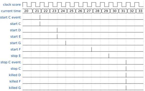
Example 5. Consider the scenario described in Example 1 and assume that structure C starts at 21 ms by triggering the IP. By satisfying the temporal constraints imposed by the composer we know that: (1) structure D starts at 23 ms and stops at 37 ms; (2) texture E starts at 23 ms and stops at 29 ms; (3) texture G starts at 24 ms and stops at 34 ms; (4) tex-ture F starts at 27 ms and stops at 31 ms; and (5) structex-ture C can stop within the time interval of [25,41] ms. Thus, if we trigger its IP at 31 ms then, structure C and its children that have not stopped yet (i.e., D, F , G) must stop immediately. We can observe in Figure 10 that our implementation satis-fies the temporal constraints of the score (described above) and the execution semantics of IS. Moreover, TRs and TOs react instantaneously to events (i.e., IPs, starting and stop-ping of TOs) due to the implementation of the FSM (Mealy FSM) and the advantages of hardware parallelism.
5. CONCLUDING REMARKS
In this paper we introduced a novel parallel implementa-tion on reconfigurable hardware of interactive multimedia
scores. We showed that our approach exploits the physical parallelism in FPGAs providing a low-latency and real-time performance of scores. Moreover, our implementation can react instantaneously to events representing IPs, starting or stopping of TOs and TRs. The current implementation of
I-SCORE does not provide this level of performance since it is executed on an operating system that does not guaran-tee a real-time performance and it does not take advantage of parallel computer architectures. We also showed that our approach correctly follows the execution semantics of IS. Moreover, it is powerful enough to express any score writ-ten inI-SCORE.
Related work. In [22], the authors compile DSP pro-grams written in FAUST (a functional programming lan-guage for real-time signal processing and synthesis) into VHDL code in order to create a fast audio processor in a single FPGA. In [5], the authors propose a system for computer music performance whose central component is an FPGA. The implemented system provides a low-latency, high-reliability, compact, and a multi-channel audio I/O per-formance. Moreover, it satisfies the low latency/jitter needed
Figure 10. Timing diagram of the simulation of Example 5. Observe that TOs react instantaneously to events.
for satisfactory reactive performance systems, thus it pro-vides a high-reliability synchronisation of acquired gestural data and sound I/O.
Future work. In IS, textures represent multimedia pro-cesses that are executed in time by external applications, such as MAX/MSP or PURE DATA. Generally, the com-poser specifies a set of values that are sent by the system and handled by external processes. Following the system pro-posed in [5], we plan to implement a Fast Ethernet module in order to provide a reliable, compact, multi-channel and low-rate communication between our FPGA system and ex-ternal applications running on standard operating systems.
The current HTSPN model ofI-SCORE provides a for-mal definition of the execution semantics of IS which al-lows to reason about the concurrent behaviour of the writ-ten scores. In this paper, we showed that interactive scores can be represented as a set of FSMs equipped with timers running in parallel. Our idea can be encoded into Timed Automata (TA) [3]. This formalism has been successfully applied in industrial case studies (e.g., [7, 15]). Then, we plan to use TA in order to specify, simulate and verify prop-erties of written scores. Unlike HTSPN, there are different multi-platform tools for the composition, simulation and au-tomatic verification (model checking) of systems modelled in TA (e.g., UPPAAL [6]). Moreover, based on the work presented in [12] and [13], we plan to synthesise the verified scores into hardware and execute them on FPGAS.
6. ACKNOWLEDGMENTS
We thank the anonymous reviewers for their detailed com-ments that helped us to improve this paper. This work has been supported by the ANR project OSSIA (ANR-12-CORD-0024) and SCRIME6.
7. REFERENCES
[1] A. Allombert. Aspects Temporels d’un Système de Partitions Musicales Interactives pour la Composition et l’Exécution. Ph.D. thesis, Université de Bordeaux, 2009.
[2] A. Allombert, R. Marczak, M. Desainte-Catherine, P. Baltazar, and L. Garnier. Virage : Designing An Interactive Intermedia Sequencer From Users Require-ments And Theoretical Background. In Proceedings of the International Computer Music Conference, 2010. [3] R. Alur and D. L. Dill. A theory of timed automata.
Theoretical Computer Science, 126(2):183–235, Apr. 1994.
[4] J. Arias, M. Desainte-Catherine, C. Rueda, and S. Sal-vati. Executing Hierarchical Interactive Scores in Re-activeML. In Actes des Journées d’Informatique Mu-sicale, pages 25–34, 2014.
6Studio de Création et de Recherche en Informatique et Musique
[5] R. Aviziensis, A. Freed, T. Suzuki, and D. Wessel. Scalable Connectivity Processor for Computer Music Performance Systems. In Proceedings of the Interna-tional Computer Music Conference, 2000.
[6] G. Behrmann, A. David, and K. G. Larsen. A Tutorial on Uppaal 4.0. Technical report, 2006.
[7] J. Bengtsson, W. O. D. Griffioen, K. J. Kristoffersen, K. G. Larsen, F. Larsson, P. Pettersson, and W. Yi. Ver-ification of an audio protocol with bus collision using uppaal. In Proceedings of the 8th International Confer-ence on Computer Aided Verification, CAV ’96, pages 244–256, London, UK, UK, 1996. Springer-Verlag.
[8] A. Benveniste, P. Caspi, S. Edwards, N. Halbwachs, P. Le Guernic, and R. de Simone. The synchronous languages 12 years later. Proceedings of the IEEE, 91(1):64–83, Jan 2003.
[9] M. Desainte-Catherine, A. Allombert, and G. Assayag. Towards a hybrid temporal paradigm for musical com-position and performance: The case of musical in-terpretation. Computer Music Journal, 37(2):61–72, 2013.
[10] R. Dubey. Introduction to Embedded System Design Using Field Programmable Gate Arrays. Springer London, London, 2009.
[11] S. Hauck and A. DeHon. Reconfigurable Computing: The Theory and Practice of FPGA-Based Computa-tion. Morgan Kaufmann Publishers Inc., San Fran-cisco, CA, USA, 2007.
[12] Y. Jiang, H. Zhang, Z. Li, Y. Deng, X. Song, M. Gu, and J. Sun. Design and Optimization of Multi-clocked Embedded Systems using Formal Techniques. IEEE Transactions on Industrial Electronics, pages 1–1, 2014.
[13] Y. Jiang, H. Zhang, H. Zhang, H. Liu, X. Song, M. Gu, and J. Sun. Design of Mixed Syn-chronous/Asynchronous Systems with Multiple Clocks. IEEE Transactions on Parallel and Dis-tributed Systems, pages 1–1, 2014.
[14] E. A. Lee. The problem with threads. Computer, 39(5):33–42, May 2006.
[15] M. Lindahl, P. Pettersson, and W. Yi. Formal de-sign and analysis of a gear controller. In Proceed-ings of the 4th International Conference on Tools and Algorithms for Construction and Analysis of Systems, TACAS ’98, pages 281–297, London, UK, UK, 1998. Springer-Verlag.
[16] R. Marczak, M. Desainte-Catherine, and A. Allombert. Real-time temporal control of musical processes. In Proceedings of the Third International Conference on Advances in Multimedia, MMEDIA 2011, pages 12– 17, 2011.
[17] C. Maxfield. The Design Warrior’s Guide to FPGAs. Newnes, 2004.
[18] E. Monmasson, L. Idkhajine, M. N. Cirstea, I. Bahri, A. Tisan, and M. W. Naouar. FPGAs in Industrial Con-trol Applications. IEEE Transactions on Industrial In-formatics, 7(2):224–243, May 2011.
[19] J. Rodriguez-Andina, M. Moure, and M. Valdes. Fea-tures, Design Tools, and Application Domains of FP-GAs. IEEE Transactions on Industrial Electronics, 54(4):1810–1823, Aug. 2007.
[20] P. Sénac, P. de Saqui-Sannes, and R. Willrich. Hierar-chical time stream petri net: A model for hypermedia systems. In G. D. Michelis and M. Diaz, editors, Appli-cation and Theory of Petri Nets, volume 935 of Lecture Notes in Computer Science, pages 451–470. Springer, 1995.
[21] S. Sutherland, S. Davidmann, and P. Flake. SystemVer-ilog for Design: A Guide to Using SystemVerSystemVer-ilog for Hardware Design and Modeling. Springer US, second edition, 2006.
[22] R. Trausmuth, C. Dusek, and Y. Orlarey. Using FAUST for FPGA Programming. In Proceedings of the 9th In-ternational Conference on Digital Audio Effects, pages 18–20, 2006.