A Comparative Analysis of Physical-Layer Rateless
Coding Architectures
by
David Luis Romero
B.S. Electrical Engineering New Mexico State University, 2009
AN CIVVS
iAASSXHUSETTS INSThWE
OF TECHNOLOGY
JUN 10 2014
IBRARI.ES
Submitted to the Department of Electrical Engineering and Computer Science
in partial fulfillment of the requirements for the degree of Master of Science in Electrical Engineering
at the
MASSACHUSETTS INSTITUTE OF TECHNOLOGY June 2014
@
Massachusetts Institute of Technology 2014. All rights reserved.Signature redacted
A uthor. ...
of Elect al Enginerin and Computer Science
SiMay
Signature
redacted
21, 2014Certified by . . ...
Certified by
/
Professor of Elect ical Engineering and Computer ScienceGregory W. WornellSignature redacted
Thesis Supervisor
... ... . .. . . r - - - - ... ..
Dr. Adam R. Margetts Technical Staff, MIT Lincoln Laboratory
Accepted by...
Signature redacted
Thesis Supervisor
/
U
U Leslie A. Kolodziejski Chairman, Department Committee on Graduate StudentsA Comparative Analysis of Physical-Layer Rateless Coding
Architectures
by
David Luis Romero
Submitted to the Department of Electrical Engineering and Computer Science on May 21, 2014, in partial fulfillment of the
requirements for the degree of
Master of Science in Electrical Engineering
Abstract
An analysis of rateless codes implemented at the physical layer is developed. Our model takes into account two aspects of practical communication system design that are abstracted away in many existing works on the subject. In particular, our model assumes that : (1) practical error detection methods are used to determine when to terminate decoding; and (2) performance and reliability as observed at the transport layer are the metrics of interest. Within the context of these assumptions, we then evaluate two recently proposed high-performing rateless codes. Using our analysis to guide an empirical study, the process of selecting the best rateless code for a given set of system constraints is illustrated.
Thesis Supervisor: Gregory W. Wornell Title: Sumitomo Professor of Engineering
Thesis Supervisor: Dr. Adam R. Margetts Title: Technical Staff, MIT Lincoln Laboratory
Acknowledgments
I would like to express my utmost gratitude to my advisor, Professor Gregory W. Wornell, whose deep insight and broad expertise guided me throughout the course of this work, and without whom this thesis would not have been possible. I would also like to thank Dr. Adam R. Margetts, whose generous sharing of expertise and time have benefited me tremendously since before the beginning of this work. A special thank you is reserved for Professor Uri Erez, whose expertise and assistance is reflected in many parts of this work. I would also like to acknowledge the generous support provided to me by the MIT Lincoln Laboratory Lincoln Scholars fellowship, which made my graduate study possible. Finally, I would like to acknowledge the support and encouragement that I received from my family and friends while completing this work, and, moreover, extend immense gratitude to my Father and
Mother, who showed me to continue moving forward when faced with difficulty.
"Once upon a time they used to represent victory as winged. But her feet were heavy and blistered, covered with blood and dust."
The Fall of Paris Ilya Ehrenburg
Contents
1 Introduction 1.1 Background . . . . 2 Preliminaries 2.1 N otation . . . . 2.2 System Model . . . . 3 System Analysis3.1 Error Detection Model and Analysis . . .
3.2 Message Error Probability . . . .
3.3 Approximate Decoding Error Probability
3.4 Packet Error Probability . . . .
3.5 Packet Throughput . . . .
3.6 Constrained System Models . . . .
4 System Design and Practical Rateless Codes
4.1 Layered C odes . . . .
4.1.1 Decoding Errors Under Successive Decoding . . . .
4.2 Spinal C odes . . . .
4.3 Design of Constrained Systems . . . .
4.3.1 Latency Constrained System Design . . . .
13 15 17 17 22 29 . . . . 3 0 . . . . 3 6 . . . . 4 1 . . . . 4 4 . . . . 4 8 . . . . 5 7 63 63 65 69 71 71
4.3.2 Reliability Constrained System Design . . . . 83
4.3.3 Short Packet Lengths . . . . 87
5 Discussion and Conclusion 95 A Layered System Architectures 99 B Design Details 101 B.1 Layered Rateless Code Design . . . 101
B .1.1 Choosing ctgt . . . . 101
B.1.2 Mean Squared Error Estimate of Effective SNR . . . 102
B.2 Complexity of Practical Rateless Codes . . . 103
B.2.1 Layered Rateless Codes . . . 104
B.2.2 Spinal Codes . . . 108
List of Figures
2-1 System m odel . . . . 23
2-2 Illustration of the structure of a packet. . . . . 26
2-3 Illustration of the structure of a rateless codeword. . . . . 27
3-1 Fraction of throughput dedicated to information bits, pt/R with R = 1/3, as
a function of undetected error probability, pue, for various information block len gth s. . . . . 35
3-2 Single decoding attempt probability of error example, k = 256, 'Ydb = 0 dB. . 43
3-3 Upper bound on probability of message error, k = 1024, -Ydb = 5 dB. . . . . . 44 3-4 Numerical examples of upper and lower bounds on the overall packet error
probability as a function of k, Ydb = 1 dB. . . . . 47
3-5 Bounds on throughput, -Ydb = 1 dB. . . . . 61 3-6 Bounds on throughput, -Ydb = 10 dB. . . . . 62
4-1 Packet error probability upper bounds for UDP design example, -Ydb = 1 dB. 73
4-2 Packet error probability bounds for UDP design example, -Ydb = 1 dB. ... 74 4-3 Throughput upper bounds and simulation results for layered, and spinal codes
for UDP design example, -Ydb = 1 dB. . . . . 77
4-4 Packet error probability upper bounds and simulation results for layered, and spinal codes for UDP design example, -Ydb = 1 dB. . . . . 78
4-5 Throughput upper bounds and simulation results for layered, and spinal codes for UDP design example, -Ydb = 8 dBe. . . . . 79
4-6 Packet error probability upper bounds and simulation results for layered, and spinal codes for UDP design example, -Ydb = 8 dBe. . . . . 80
4-7 Throughput upper bounds and simulation results for layered, and spinal codes
for TCP design example, -Ydb = 1 dB. . . . . 85
4-8 Throughput upper bounds and simulation results for layered, and spinal codes for TCP design example, -Ydb = 8 dB. . . . . 86
4-9 Packet error probability bounds for UDP design example with short packet
length, /db = 1 dB . . . . 88
4-10 Throughput upper bounds and simulation results for layered, and spinal codes for UDP design example with short packet length, Ydb = 1 dB. . . . . 90
4-11 Packet error probability upper bounds and simulation results for layered, and spinal codes for UDP design example with short packet length, -Ydb = 1 dB. 91
4-12 Throughput upper bounds and simulation results for layered, and spinal codes for UDP design example with short packet length, Ydb = 8 dB. . . . . 92
4-13 Packet error probability upper bounds and simulation results for layered, and spinal codes for UDP design example with short packet length, -Ydb = 8 dB. . 93
A-1 Three layer communication system architecture. . . . 100
B-i Throughput efficiency for M = L = 7 layered codes vs SNR. Various choices
of Etgt are show n. . . . 102
B-2 MSE and measured effective SNR when attempting to decoder layer 7. . . . 103 B-3 Average receiver operations per goodbit for spinal and layered rateless codes. 112
List of Tables
2.1 Deterministic Scalar Quantities . . . . 18
2.2 E vents . . . . 19
2.3 Random Scalars, Vectors, and Matrices . . . . 20
2.4 Layered Code Parameters . . . . 21
2.5 Spinal Code Parameters . . . . 21
3.1 Summary Of Basic Error Events . . . . 31
4.1 Simulation Configuration, k = {256, 512, 1024} . . . . 76
4.2 Spinal Code Throughput Comparison, k = 1024, _Ydb = 1 dB . . . . 81
4.3 Receiver Ops. Per Goodbit, k = 1024, _Ydb = 1 dB . . . . 82
4.4 Short Packet Length Simulation Configuration, k = {64, 128, 256} . . . . 89
B. 1 Real Arithmetic Operations Required To Compute And Apply UMMSE Com-bining Weights For Layered Rateless Code. . . . 106
B.2 Real Operations Required By The Turbo Decoder To Decode The Layered R ateless C ode . . . . 108
Chapter 1
Introduction
Rateless codes are forward error correcting codes for which the number of encoded symbols used to communicate a given message varies with the channel. This is in contrast to tra-ditional fixed rate codes, which attempt to communicate using a fixed number of encoded symbols and are not capable of dynamically adapting to each channel realization. The highly adaptive nature of rateless codes make them an attractive choice for systems that operate where the communication channel is unknown, or varies over time in an unknown manner.
A number of methods exist that can be used to enable a system to adapt to uncertainties
in a channel. In a broad sense, all of these methods fall into the category of variable rate codes1. One sub-class of such codes is based on shortening a block of information symbols,
which are subsequently encoded into a fixed length codeword [1]. Another sub-class of
vari-able rate codes are designed to encode a fixed number of information symbols into a varivari-able length codeword using either code extension, or puncturing and incremental transmission [2]. Still other variable rate codes use some combination of shortening, and extension or punc-turing [3]. In this thesis, we consider only variable rate codes that encode a fixed number of information symbols into a variable length codeword, and refer these as rateless codes.
Rateless codes have long been of interest to the coding community. After practical constructions were successfully applied to erasure channel models [4], an interest in
oping rateless codes for noisy, physical layer channel models emerged. It has since been demonstrated that practical constructions of such codes are possible, and can achieve good performance [5, 6, 7, 8].
Typical analyses of rateless codes appearing in the literature focus on performance as observed at the physical layer (PHY) and medium access control layer (MAC) of the system (See Appendix A). Additionally, many existing analyses assume a model in which the receiver behaves as if knowledge of the transmitted message is available after decoding, enabling the decoder to detect with probability 1 whether decoding decisions are valid.
Such perspectives are useful for distinguishing code performance from other characteristics of the system. However, once a set of candidate rateless codes with good performance has been identified, a system designer must evaluate their performance when coupled within the system. Such an evaluation must take into account performance and reliability as observed at the application layer of the system, as these metrics most closely affect user experience. Furthermore, systems must utilize an error detection scheme that provides some imperfect level of reliability, as a "genie" aided receiver is not possible in practice.
The above considerations must be taken into account when designing any communication
system. However, when considering rateless codes it is particularly important to take the effects of imperfect error detection into account, as decoding and error detection are typically executed repeatedly for each message, leading to an aggregate probability of undetected error that is substantially higher than in the case of fixed rate codes. Additionally, because application level performance and reliability is impacted by protocols that operate within the transport layer of the system (See Appendix A), it is important to consider such protocols when undertaking a detailed system analysis.
In this thesis, we analyze the performance and reliability of rateless codes with the goal of
contributing a more detailed system analysis than what has typically appeared previously in the literature. While previous works have abstracted away certain details to produce useful course grained analyses of rateless codes, we develop a finer grained analysis by considering
a model employing fewer analytical simplifications. In particular, we analyze performance and reliability from the perspective of the transport layer of the system, while assuming use of a practical error detection method.
Our analysis is executed in two phases. First, a model of rateless codes is presented and analyzed. The model is anchored at the transport layer of the system, and is used to capture the dominant effects of a practical system employing such codes. The analysis yields a set of bounds on the throughput and probability of error that one can expect to observe at the application layer of the system, given a set of design parameters. Second, simulation of two high performing practical rateless codes is used, along with our analysis, to illustrate how a system designer can select an appropriate rateless code given a set of constraints on the system. The primary goal of this thesis is to provide insight and practical examples of interest to system designers who are considering the use of rateless codes.
The remainder of the thesis is organized as follows. In the following section a brief summary of previous work on rateless codes is provided. In Chapter 2 notation is defined, and a detailed description of the basic system model for rateless codes is given. In Chapter
3, a basic system model of rateless codes is analyzed. In Chapter 4, layered and spinal
codes are described, and Monte Carlo simulation results are presented within the context of illustrative design examples. Finally, the thesis concludes with a brief discussion in Chapter
5.
1.1
Background
Several fundamentally different approaches to rateless coding have been introduced over time. One notable example is automatic repeat request (ARQ) systems. In an ARQ system, the transmitter resends previous messages upon receiving feedback from the receiver that a codeword was decoded in error. The receiver may use some method of combining the repeated transmissions. Other examples are hybrid-ARQ (HARQ) systems, which encode
messages using a forward error correction (FEC) code, then send a subset of the parity symbols, only sending additional parity symbols upon request from the receiver. HARQ systems have been practically deployed, for example using the current LTE standard [9].
A more sophisticated approach to rateless coding is that of fountain codes, which can,
in principal, generate an infinite stream of distinct encoded symbols to be sent across the channel. A notable example of fountain codes that were designed for erasure channel models
are the Raptor codes of [10]. Raptor codes were later adapted to physical layer channel models in [5]. Spinal codes [7], which are one of two practical rateless codes considered in this thesis, fit into the fountain paradigm, and have been shown to perform well when applied to physical layer channel models.
Another approach suited to physical layer channel models is to construct a rateless code using layering and repetition of a set of base codebooks. This is the approach taken for the
layered codes of [6], which is the other of two practical codes that are considered in this thesis.
In general, spinal codes have been shown to perform well for short information block lengths, while layered codes employing turbo codes for the base codebook have been shown to perform well at long information block lengths. Because of their demonstrated performance in different information block length regimes, it is of interest to compare and contrast the performance of the two codes over the span of short and long information block lengths.
Chapter 2
Preliminaries
2.1
Notation
Events and sets are denoted using calligraphic characters (A). The complement of event (or set) A is denoted Ac. The cardinality of a set, A, is denoted JAI, while the probability of event A is denoted P (A). Random quantities are denoted using lower case or upper case sans serif characters (b, or B, respectively), whereas deterministic quantities appear as either lower case, or upper case serifed characters (b, or B, respectively). Vectors (deterministic or
random) are denoted using lower case, bold face characters (v if deterministic, v if random), while matrices are denoted using upper case, boldface characters (G if deterministic, G if random). Deterministic scalar quantities, events, and random scalars, vectors and matrices are summarized in Tables 2.1, 2.2, and 2.3, respectively. Parameters that are particular to the layered, and spinal rateless codes, which are evaluated in this thesis, are defined in Tables 2.4, and 2.5, respectively. Though some quantities such as vectors and events are initially defined using indices and subscripts, if there is no risk of ambiguity or confusion, such indices and subscripts are dropped during exposition for convenience.
Table 2.1: Deterministic Scalar Quantities
Symbol/Defintion Description
k Number of information bits encoded into a single variable rate codeword.
b Number of bits dedicated to error detection for each k bit message.
t Number k - b bit subpackets contained in one packet.
n Number of channel uses.
ni Cumulative number of channel uses corresponding to a
single message after i decoding attempts.
nIRU Number of channel uses observed between consecutive
decoding attempts; i.e. the length of an incremental redundancy unit (IRU).
m Maximum number of IRUs (i.e. decoding attempts)
corresponding to one message.
ntrials Number of Monte Carlo simulation trials.
Pue A P ('P|) Probability of false CRC pass given a decoding error. P Overall error probability for latency constrained cases.
Pr Overall error probability for reliability constrained cases.
C Shannon channel capacity.
Cf b Capacity of feedback channel.
R System throughput.
R, Throughput for latency constrained cases.
Rr Throughput for reliability constrained cases.
pA Instantaneous throughput.
Average channel signal to noise ratio, linear units.
'/db Average channel signal to noise ratio, decibel units.
ntx Maximum number of packet transmissions dedicated to
Table 2.2: Events
Symbol/Definition Description
Si= (ni) Decoding error given ni channel uses.
Pi =P(ni) Checksum (CRC) pass event.
Zund = Zud(ini) A Si
n
P, Undetected decoding error given ni channeluses.
Zdet(ni) A Ein 'Pi Detected decoding error given ni channel
uses.
Si = St(ni) A En 0 P. Detected decoding success given ni channel uses.
TA
Ut
(Zyndn
(n-Zet))
Undetected decoding error, 1th codeword.Dm A
E
U(n
IZiet)
Message error event, 1th message.F A ULID Packet error event given a packet of t
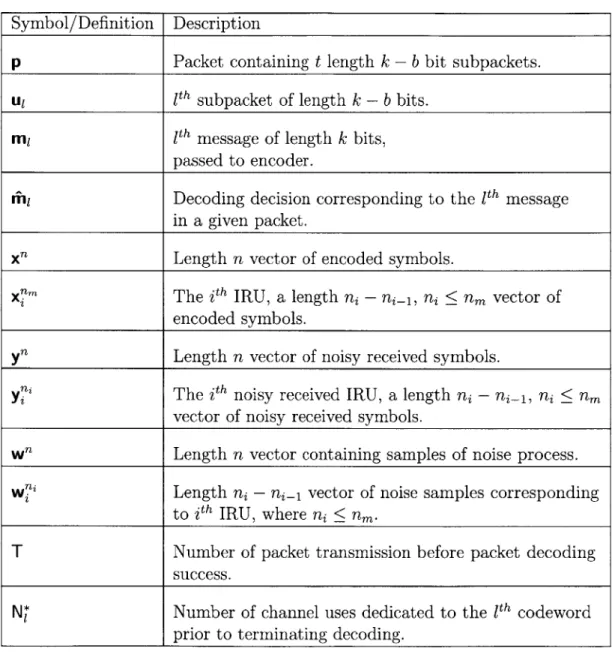
Table 2.3: Random Scalars, Vectors, and Matrices
Symbol/Definition Description
p Packet containing t length k - b bit subpackets.
U1 1"h subpacket of length k - b bits.
m1 11h message of length k bits,
passed to encoder.
rM1 Decoding decision corresponding to the 1th message
in a given packet.
" Length n vector of encoded symbols.
" nThe ith IRU, a length ni - ni_1, ni < nm vector of
encoded symbols.
yfl Length n vector of noisy received symbols.
yi The ith noisy received IRU, a length ni - ni- 1, ni < nm
vector of noisy received symbols.
w n Length n vector containing samples of noise process.
w? niLength ni - ni_1 vector of noise samples corresponding
to ith IRU, where ni < nm.
T Number of packet transmission before packet decoding
success.
N* Number of channel uses dedicated to the 1th codeword prior to terminating decoding.
Table 2.4: Layered Code Parameters
Table 2.5: Spinal Code Parameters
M Maximum number of redundancy blocks for layered rateless codes.
L Number of layers corresponding to one layered rateless codeword.
G Complex layer combining matrix.
Etgt Target bit error rate used to design G.
rb Rate of base code when complex transmit symbol and FEC code
rate is taken into account.
N Length of each turbo base code, in channel uses.
k' Number of message bits (out of k) which make up one hash key in a spinal encoder.
v Number of bits which specify each spinal value.
c' The alphabet of complex transmit symbols has a cardinality of 22',
i.e. c' bits are mapped to each real and imaginary part of the symbol.
B Beamwidth of spinal decoder.
2.2
System Model
Our analysis assumes a discrete time baseband forward channel model that is corrupted
by additive white Gaussian noise (AWGN). Rateless coded communication takes place over
the forward channel, which is characterized by its Shannon capacity, C, in units of bits per channel use, where a channel use is defined as the unit of time required to send one
complex symbol over the forward channel. Note that the forward channel can equivalently be characterized by its average signal to noise ratio (SNR), -Ydb, in units of decibels.
A feedback channel is used to inform the transmitter when decoding success (or failure)
has been detected by the decoder. The feedback channel can be used as frequently as once per forward channel use. The transmitter uses feedback information to determine whether to begin transmitting the next message, or to send additional encoded symbols so that the receiver can again attempt to decode. The simple acknowledgment/negative acknowledgment
(ACK/NACK) feedback scheme considered in this thesis implies that one bit of information
per use of the feedback channel is required. The feedback channel is characterized by its capacity, CfA. Throughout this thesis, it is assumed that the feedback channel has zero delay,
and Cfb ;> 1 bit per channel use.
It is common when analyzing rateless codes (e.g. [7, 8]) to assume a genie aided system. Perfect error detection is possible under this assumption, as it enables the decoder to compare the estimated and true messages, thus allowing the decoder to detect with probability 1 whether a decoding decision is correct. When a genie aided system is not assumed (which is the configuration of interest in this thesis), it is common to dedicate a number of the information bits that make up each message to error detection. If b out of k message bits are used for error detection, then these b bits function as a "checksum" that is used to verify the integrity of the decoding decision (i.e. the remaining k - b bits) with some level of reliability. While other methods of error detection that do not require a b bit overhead are possible under certain rateless coding schemes', these alternative methods are not considered
Packet Packet Queue Buffer Ip p Segment/ Reass./ Queue w.m Buffer Ui CRC Rateless i Zfm Rateless CRC
Encoder Encoder Decoder Decoder
Feedback Channel
Figure 2-1: System model
in this thesis because they tend to be coupled to the particular type of rateless code under consideration.
In many practical systems, a b bit cyclic redundancy check (CRC) is used for error detection. Because it is ubiquitous, and is not coupled to a particular type of rateless code, this method is assumed for the remainder of this thesis.
In terms of functional units, the system consists of one transmitter, and one receiver. The transmitter consists of a packet queue, a segmentation/queueing unit, a CRC encoder, and a rateless encoder. The receiver is made up of a rateless decoder, a CRC decoder, a reassembly/buffer unit, and a packet buffer. A functional system block diagrams is illustrated in Figure 2-1.
It is assumed that the packet queue contains an endless stream of transport layer packets
of information bits. Each packet is denoted p, and is made up of t subpackets, each of which is made up of k - b bits. Hence, each packet consists of t(k - b) bits. It is assumed that b' out of the t(k - b) bits in each packet form a b' bit CRC which is used to verify the integrity
can be accomplished using the syndrome of the LDPC code. As another example, rateless codes employing iterative decoders can leverage soft reliability metrics for reliability based error detection [11].
of the decoding decisions after all such decisions corresponding to a given packet have been made. Note that transport layer packets model data units that are passed from the transport layer to the MAC and PHY layers of a communication system (See Appendix A).
We next consider the operation of the system, which can be described by the following sequence of events.
1. A large packet of bits, p, is segmented into t distinct subpackets, each denoted u for
1 = 1, 2, ... , t, where each u1 contains k - b bits.
2. A b bit CRC is computed and appended to each u1, resulting in t distinct k bit messages,
each denoted ml.
3. The first message, mi, is passed to the rateless encoder, which maps mi --+
xm-{
X0, x1, - - , x m-1}, where each scalar x3 E Xnm is a complex encoded transmit symbol that costs one channel use to send to over the channel. Note that for a rateless code, in principal, nm could be infinite.4. The first incremental redundancy unit (IRU), a subset of the encoded symbols xim
c
xm, x1m = {xIx 2, ... ,x 1}, is sent over the channel.
5. After observing the channel output, the decoder makes a decision, denoted i1, based
on the received sequence y"1 = Xnm + W"l, where Wfl is a length n1vector of complex
baseband samples of a white Gaussian process.
6. The decoder computes a checksum for iin1 to verify the integrity of the decoding
deci-sion. If the checksum passes, an ACK is sent over the feedback channel, which signals to the transmitter that it can commence encoding and transmitting m2. If the
check-sum fails, a NACK is sent over the feedback channel2, causing the transmitter to send
the second IRU, X2m, over the forward channel.
2
7. If necessary, additional IRUs are transmitted, and steps 5-6 are executed after the
receiver observes each IRU until the checksum corresponding to m- 1 passes, at which
time the system begins executing Step 3 for the codeword corresponding to m2.
8. Once all t message decisions, mi, have been acquired by the receiver, the CRC bits are
removed and the resulting subpacket estimates, U-1 for 1 E 1, 2,.-. , t, are reassembled
into an estimate of the transmitted packet, P [1, l2, -- , Ut].
9. The integrity of P is checked using the b' bit CRC checksum. If the checksum passes,
the receiver informs the transmitter via the noiseless feedback channel, and the system starts the process over at Step 1 for the next packet in queue. Otherwise, the packet is retransmitted, or dropped.
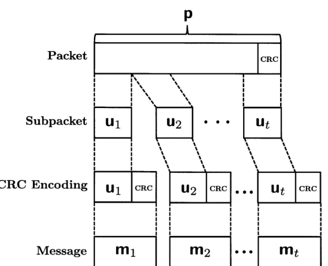
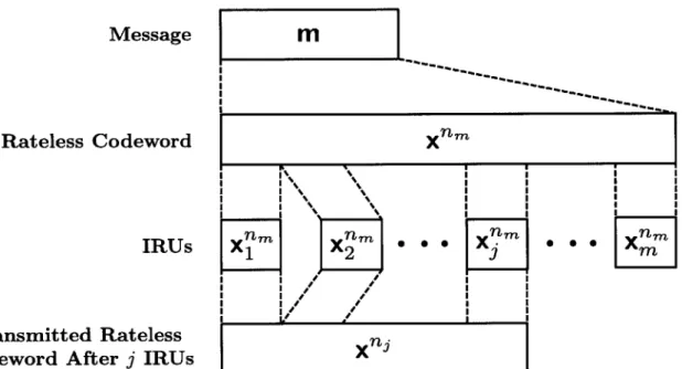
Note that all t of the mi E p must be correctly estimated, else the packet must be retransmit-ted or dropped, depending on the network protocol. Figure 2-2 illustrates the structure of a packet, and its relation to its constituent subpackets and messages. Figure 2-3 illustrates the
structure of a rateless codeword and its relation to its constituent IRUs. Note that Figures 2-2 and 2-3 also help to elucidate some of the notation defined in Tables 2.1 - 2.3.
Packet
Subpac
CRC Encodi
Messa
p
CRCkcet
U1
.2
-ng
U11CCU
R Rge
MIM2
MtMessage
Rateless Codeword
Transmitted Rateless Codeword After j IRUs
mZIX
x nm 0 00 I I I I I I I I I I I IF~1
I I I I I I I I I I * I x njFigure 2-3: Illustration of the structure of a rateless codeword.
\ \ % IRUs XX I I
1
| 0P I v * I * I * I * I I I I I 0 00Chapter 3
System Analysis
Many existing works on rateless channel codes [6, 7] are based on analysis and empirical results corresponding to performance as observed at the MAC and/or PHY layers of a communication system architecture (see Appendix A). Furthermore, many works assume that the decoder is omniscient in that there exists no uncertainty pertaining to detecting when a correct decoding decision is made. While such analysis is useful for isolating code performance from other effects in the system, it can be inadequate for designers who are ultimately interested in the overall performance of such codes when they are integrated into the overall system architecture. Motivated by this fact, this chapter develops an analysis of rateless codes for the AWGN channel. Important features that differentiate this development from other works on rateless codes are:
1. Imperfect error detection is used at the receiver
2. Performance and reliability as observed at the transport layer is of interest
Integrating features 1) and 2) throughout, our development yields a model that is useful to system designers who are considering the tradeoffs involved in choosing between different rateless codes, and guides the selection of important design parameters (e.g. information block length, CRC length). The resulting set of equations and inequalities that represent
the model can help guide the beginning stages of the design process. Rather than having to immediately resort to hours (or days) of simulation, our analytical model provides a compact representation of the performance and reliability that one can expect to observe given a rateless code, a set of design parameters, and system constraints.
Throughout the analysis, important equations and inequalities are placed in rectangular boxes for emphasis.
3.1
Error Detection Model and Analysis
In this section, a CRC method of error detection is defined and analyzed. Our analysis shows
that, given a b bit error detection CRC, the probability of undetected error conditioned on an incorrect decoding decision, denoted pue, can be approximated as:
Pue ~ 2-b (3.1)
Under rateless coding, several kinds of errors are possible. For example, say that a par-ticular receiver has acquired a sequence of noisy observations corresponding to a transmitted rateless codeword made up of i IRUs (See Figure 2-3). The decoding error event, Si (equiv-alently denoted as S(ni)), occurs if M-i f m, where iin is the tentative decoding decision given all information available at the receiver, and m is the message that was encoded at the transmitter. The probability of a decoding error occurring, P
(Ei),
is generally dependent upon the channel SNR, the block length ni, and on the particular method of encoding and decoding that is used.Another error that is possible under rateless coding (and, more generally, under any communication scheme) occurs when a decoder fails to detect an error in a tentative decoding decision. The event associated with error detection, Pi, occurs when the error detection check returns a positive result1. Under practical error detection methods, P (Pi) is dependent upon
Table 3.1: Summary Of Basic Error Events
__S_ __ _ _ _ _ _sic
Pi Undetected Error Detected Success
P Detected Error False Detected Error
the particular method of error detection, and the bit error rate of the tentative decoding decision [12]. To simplify our analysis, we assume an error detection model that depends only on the method of error detection, and whether the ith decoding decision is correct. Error events corresponding to a codeword of length ni channel uses and their interactions and associated penalties are summarized in Table 3.1.
When employing rateless coding, error events corresponding to a given message can be characterized by a sequence of events (and their complements) such as those listed in Table
3.1. Stated more formally in terms of our notation, error events for a given message, m,
occur over a sequence of decoding attempts that are executed on a sequence of codewords
of increasing lengths {ni, n2, ..., ni}, where ni is the length at which either si
n
Pi or E9n
Pioccurs. In principle, ni can go to infinity, though in practice it is typically limited to some system dependent value nm. For notational convenience, the undetected, and detected error events are defined, respectively, for a length ni codeword as:
Zlund = E n P, (3.2)
zdet S.E n 'Pi (3.3)
Similarly, the event corresponding to a detected decoding success given a length ni codeword is defined as:
Assuming a maximum codeword length of nm, the overall undetected error event,
El,
corre-sponding to the 1th message, where 1 E 1, 2, ... , t, is defined as the following disjoint union:
A Zund u Z"nd
n
Zdet U ... U (Zm" n Zdetn... n Z "
(
(Z
dn
zet (3.5)i=1 j=1
Next, the event ZLnd = 6i
n
P is considered in order to gain basic insight into the performance-reliability tradeoff that exists for a rateless code.The undetected error event, Z1Id, incurs a penalty on the overall probability of error of the system, as the receiver erroneously believes that in = m. Note that the false detected
error event in Table 3.1, e
n
Pf, is assumed to have probability 0.Because the event Znd is very detrimental from a system reliability standpoint, as it
potentially allows many erroneous bits to pass through the MAC and PHY layers toward the user application, it is useful to first understand P (ZInd), the probability of an undetected
error given a decoding error on a codeword of length nI. Using elementary laws of probability, we rewrite the probability of undetected error as:
P (Znd) =IP ( 1 n P1)
=ED (F1 S,) 1P (E1l) (3.6)
Referring to the right side of (3.6), note that P (Si) is a function of the channel SNR (which partially determines the probability of a decoding error), and the particular rateless code that is used. From the perspective of analyzing a given error detection model, we are interested in P (P1
S)
= P (Pi ES), which depends only on the method of error detection, conditionalenables an analysis of this perspective2
For convenience, we define:
Pue A P (Pi s (3.7)
Note that in the case of the genie aided system discussed in Section 2.2, we have pue = 0.
As stated previously, we consider systems that use a b-bit CRC for error detection. This method allows a designer to decrease pue by increasing b. Thus, as reliability increases, throughput decreases. It is probabilistically possible for a CRC to pass when a decoding error has occurred (i.e. for a CRC collision to occur). This can be understood by thinking of a b-bit CRC as partitioning the set of possible binary messages, A, where 1A1- 2k-b, into
a sequence of 2' subsets, {Aj}, for j = 0,, ..., 2 1. Each A contains all of the length k - b
bit binary messages which collide with each other under the given b-bit CRC; i.e. JAjj= 2k-2b for each j = 0, 1,, 2' - 1. Under the assumption that each erroneous ii- is equiprobable
given that a decoding error has occurred, the probability that a set of decoded message bits will erroneously pass the CRC can be expressed and upper bounded as:
JAI -1 2k-2b _1 2k-b - 1 2k-b -2k-b - 1 < 2-b (3.8)
2It has been shown [12] that, for certain classes of cyclic redundancy check polynomials that can be used
for error detection, the model used in this work for pue is accurate in the SNR regime where the bit error rate of the CRC codeword is high. This turns out to be a reasonable model for rateless coding, because many decoding attempts occur when the rateless codeword is much shorter what is required to successfully decode, leading to a high bit error rate at the the output of the decoder.
where (3.8) follows from the fact that 2k-b 2 < 1 whenever 2 b > 1, or equivalently, when
b ;> i.
A lower bound can be derived by considering the error in the upper bound as follows:
2k-2b - 1 2-b( 2k-b - 1) - 2k-2b + 1 2k-b - 2k-b - 1 2 k-2b -2 -b - 2 k-2b + 1 2k-b - 1 1 -2 2k-b - 1 1 < 2k- -
1
(3.9) (3.10)where (3.9) is strictly greater than 0 for b > 0 and k > b, and (3.10) is true under the former condition on b.
Using (3.8) and (3.10) we arrive at:
2 - E < Pue < 2-b (3.11)
where 6 = 2k-b-. Clearly, c - 0 quickly for reasonable values of k - b (for example, if
k = 256 and b = 24 we have E e 1.4489 x 10-70). Thus, under the current model for error
detection, we are justified in using the approximation pue ~ 2b, which given in (3.1).
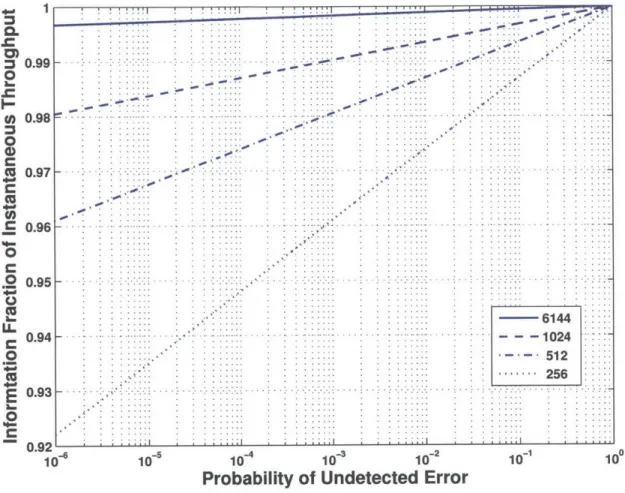
To make the throughput-reliability tradeoff concrete, consider the relationship between the instantaneous throughput, pt A k , and pue. Using the approximation given in (3.1), pt
can be expressed as:
k + log2(pue)
Pt ,r.. (3.12)
Note that, for a rateless code, the number of channel uses, N*, required for the CRC to pass is a random variable. For illustration purposes, in this section we take N* = ni.
Figure 3-1 illustrates the throughput-reliability tradeoff for several information block lengths (as labeled in the figure legend). Note that the sequence of curves is characterized
by a slope that increases as the value of k is decreased, illustrating the performance cost
associated with various levels of reliability.
1 0. 0) W *0 0 0 U. C LL
.c
C 0.99 0.98 0.97 0.96 0.95 0.94 0.93 10~ :. .... . . - 6144 - - - 1024 - 512 256 dO p oo 10-4 10 10-2Probability of Undetected Error
10-1 100
Figure 3-1: Fraction of throughput dedicated to information bits, pt/R with R = 1/3, as a function of undetected error probability, Pue, for various information block lengths.
10 s -. . -
4-3-3.2
Message Error Probability
In Section 3.1, it was illustrated that CRC based error detection provides a mechanism to control the reliability of decoding decisions. Furthermore, it was shown that each measure of
reliability has some associated performance cost. A model for this method of error detection was presented, and the associated performance-reliability tradeoff was illustrated for the case of a single decoding attempt. In the rateless setting, a sequence of decoding attempts, in
which error detection is performed after each attempt, may be necessary. Hence, the effect of error detection on the overall reliability of each encoded message is more complex than was illustrated in the single decoding attempt case. In this section, the results developed in
Section 3.1 are extended to characterize the overall reliability associated with transmitting a single message. Before proceeding with a summary of the main results and corresponding analysis, let us define the primary event of interest.
Let D, denote the error event corresponding to the 1"h of t messages that make up a transport layer packet. A message error event occurs if either an undetected decoding error occurs, or some agreed upon maximum number of detected decoding attempts, m, has been reached3. Thus, D, can be defined as:
SA
E
U Zet (3.13)The main results developed in this section are as follows. We derive lower, and upper bounds on the overall probability of undetected error corresponding to message 1 (as defined in (3.5)), which can be expressed as:
(3.14) P (S > EPue (I - Pue)i- P (E)
i=1 j=1
3
In this case, the transmitter and receiver may agree to "give up" on message 1, or perhaps on the entire packet, depending on the application of interest. This issue will be addressed when we consider constrained system models in Section 3.6.
(3.15)
P (s,
Zpue
(1
- Pue)<-P (Vi)The upper bound given in (3.15) is then used, along with a bound on the probability of the overall detected decoding failure event, P
(nli
Ziet), to express the following upper boundon P (D1), the overall probability of error associated with message 1 :
P(D) < Zpe (1 -pue-P (ES) + (1 pue)mP (Sm)
To begin our analysis, we express the probability of the event (3.13) as:
P (D) = P Zfet
(3.16)
)
P (E) +P ( ziet (3.17)
where (3.17) uses the fact that the undetected decoding error event and
fli
1 Ziet are disjoint (viz., (3.3), (3.5)).The contribution of the second term on the right side of (3.17) is first considered. This term can be rewritten and upper bounded as:
P
(zet
= P (Zre) i=1 P Z det i \ _j =m-i+1 <P (Zdet) (1 - pue)m-1 P ('P Em) P (Sm) (1 - pue)m-(1 - Pue)mP (Sm) Zdet) Z ) (3.18) (3.19) (3.20) M U( n
where (3.18) follows from the chain rule for joint probabilities, (3.19) follows from the fact that L1 EP (Zdet.
fT
72 m-i+ ) (1 - Pue)m 1, and (3.20) is based on the definition(3.7).
To bring system operational insight into the sequence of expressions (3.18) - (3.20),
consider the following: if the product due to the chain rule in (3.18) is collapsed we get:
m m m-1
rip
(zm±
2 n ziet) = n ziet gzet (3.21)i=1 M-i+1 (i=1
which is the joint probability that the first m-I transmissions result in a sequence of detected decoding failures given that the mth decoding attempt resulted in a detected decoding failure. Intuitively, if a message can not be decoded using a codeword of length nm, then there is a high probability that it could not be decoded at any length ni < nm, which suggests that
(3.19) may be reasonably tight.
Given (3.20) and the discussion above, a preliminary upper bound on the overall message error probability can be expressed as:
P (DJ) < P (Et) + (1 - pue)mI? (Sm) (3.22)
We next focus on the first term on the right side of (3.22), the overall probability of undetected error corresponding to the 1th of t messages associated with a given packet. The
exact evaluation of this term is difficult, even for moderate m. However, in what follows we show that using a small amount of operational insight enables us to derive upper and lower bounds on P (E) that are easily evaluated. We begin by expressing P (E) as follows:
P ES =P
U
zun
nzde
(i=1 j=1
m i-1
J:P
n
un-dn idet(3.23)i=1 j=1
where (3.23) follows from the fact the E' is equal to the disjoint union in (3.5). From Equation
(3.23), it can be seen that P (9E) can be bounded by bounding each term in the summation.
Hence, we expand each term as follows:
d e und
net
_ p und et et detj=1 j=1 (j=1
i-1 i-1 i-1
j=1 j=1 k=j+1
j=1 j=1 k=j+1
(3.25)
where (3.24) follows from the chain rule for joint probabilities, and (3.25) follows from the definitions of Ziund and Zidet, along with the fact that, under the current error detection model, P (PtISi n A) = P (PtIS,) for any arbitrary event A.
Now, consider the term P (si
n-
Zjet), which is the conditional probability of a de-coding error occurring on attempt i, given that detected dede-coding errors have occurred for previous decoding attempts j = 1, 2, - - -, i - 1 for the current codeword. Using Bayes rule,P 6i
n
Zdet -(flilz
et ))(3.26) etFqt Z beau)
From an operational perspective, we argue that P
(-i
Z ets)
>
P(Oi-i
Z5 et), becauseconditioning on a decoding error on the ith decoding attempt clearly can not decrease the
probability that decoding attempts
j
= 1, 2, - - - , i--1 result in errors for a stationary channel. Stated in other words, for a fixed message size k, knowledge of future decoding errors doesnot decrease the probability of past decoding errors for a codeword which increases in length with each decoding attempt, as it does for rateless codes. Hence, it can be concluded that:
P
Ei n zdet > P (8i) (3.27)j=1
Now consider the terms in the product of (3.25). Following the same operational argument that was used to justify (3.27), each of these terms can be lower bounded as:
P Ej n Zdet) P (Ej) (3.28)
k=j+1
Combining the inequalities (3.27), and (3.28) into (3.25) results in the lower bound given in (3.14).
To derive an upper bound on the terms in the summation of (3.23), consider the following sequence of equations and inequalities:
F (Zund ~q(~zet) =FZnd)Fo det -)Znd)
-1 i-i
= d (Zu) F Pzde t Z nd Z (3.29)
k=+
=1k
pue(i) (1p~) fJ
ni
Zi~ed(y
zdej'(3.30)
j=1 i--1 l kkj±1 --1
j=1 k=j+1
where (3.29) follows from the chain rule for joint probabilities, (3.30) results from the def-initions of Ziet, and Zind, and from the assumption that error detection is conditionally independent of any additional events given the current decoding outcome. The inequality in (3.31) is based on the fact that 1 1 E Zn 0 ( +1 4et) <land the same
operational insight that led to (3.27), and (3.28). Note that (3.31) can be extended by
dropping the conditional probability F (Ei-1 Zund ) , as this term is likely close to 1 due to conditioning on a future decoding error. The upper bound given in (3.15) follows.
Note that applying (3.15) to (3.22) yields the message error probability given in (3.16).
As an additional point, note that if it is assumed that the system is operating in an SNR regime where successful decoding is possible for some system capable value of nm, then
P (E,,m) = 0, and the overall message error probability can be lower bounded by (3.14).
From a computational standpoint, the bounds in (3.14) - (3.16) are attractive as a design
tool because they are each a function of only Pue, and the marginal probabilities of decoding
error events over m decoding attempts. The only component of these bounds that has not yet been developed, but is required for evaluation, is a model for the marginal probability of decoding error, P (.E). In Section 3.3, two such models are described.
3.3
Approximate Decoding Error Probability
In this section, a method of approximating the marginal probability of decoding error is presented. The method is based on random coding arguments, thus providing an optimistic characterization of performance and reliability that can be used as a benchmark when con-sidering practical rateless codes.
The model we consider is based on error exponent analysis and jointly typical sets. Con-ceptually, the decoder for this model can be thought of as making decisions based on whether the the received sequence is jointly typical with a unique codeword from the codebook. This
1. There exists a codebook of 2k unique codewords which each correspond to a unique k
bit message. The codebook is known to both the transmitter and receiver.
2. Each codeword, Xflm - {X1, X2, ... , Xfm} for i E {1, 2, ..., 2k}, is a length nm sequence of encoded symbols, where each symbol is drawn iid according to some probability distribution p(x). Additionally, each encoded symbol has power constraint P; that is, for any symbol xj
E
Xfm, E[x] = P.3. The encoded symbols are sent incrementally over the channel, which outputs yf, a
distorted version of n encoded symbols, where n < nm.
4. Each encoded symbol sent over the channel is distorted according to the transition distribution p(ylx). As stated in Section 2.2, the channel transition distribution of
interest in this work is AP (x, U2).
5. Each time the channel outputs additional distorted symbols corresponding to a given
k bit message, the receiver attempts to decode by looking in the codebook for a unique codeword of length n that is jointly typical with the received sequence, according the
distribution p(X", yn) = 1 p(xy).
Additional details on jointly typical sequences and decoding can be found in Chapter 7 of
[13], which also provides a detailed derivation of the error exponent for such a decoder. The
important result of this derivation (for the current purpose) is that the average marginal probability of decoding error corresponding to a length ni codeword can be bounded as:
P (,Ei) < 2 "aaN-- (3.32)
with SNR -y = P , and small constant 6 > 0. The bound in (3.32) is most accurate in cases
where the code block length, ni, is long.
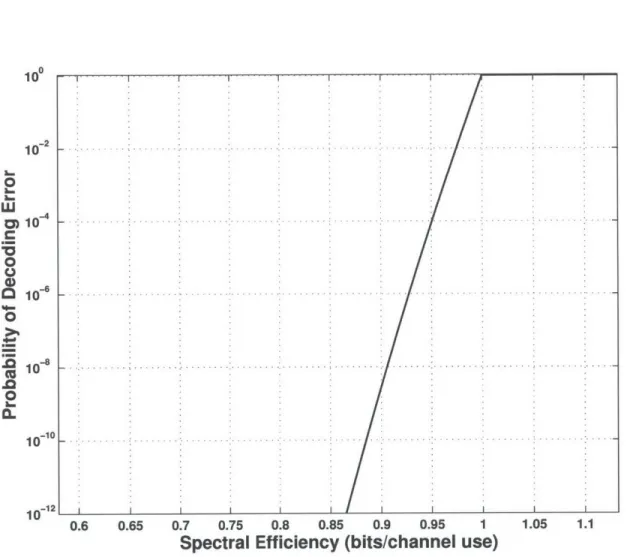
Figure 3-2 illustrates (3.32) for a k = 256 bit rateless code over a complex AWGN channel
(equivalent to spectral efficiency in this case). Note that, though the error exponent curve represents an upper bound, for the reminder of this thesis, we use the approximation.
P (Vi)
-100 10-2 a-0 L. 0 0 1-6 0 10 -0 2 * (3.33) 10-*0 10-12 0.6 0.65 0.7 0.75 0.8 0.85 0.9 0.95 1 1.05 1.1
Spectral Efficiency (bits/channel use)
Figure 3-2: Single decoding attempt probability of error example, k = 256, -Ydb = 0 dB.
Figure 3-3 illustrates the upper bound in (3.16) plotted as a function of pue for a complex
AWGN channel with capacity C ~ 2.06 bits per channel use (-Ydb = 5 dB). In this example, the information block length is k = 1024 bits, nIRU = 1, and nm = 8192 (i.e. decoding
attempts are executed after every encoded symbol is received, up to nm = 8192 symbols).
100 10 102 10 10 10-6 10 1u 10 10~- 10- -7 10- 10~5 10 10 1
Probability of Undetected Error (Pue)
10 10~ 100
Figure 3-3: Upper bound on probability of message error, k = 1024, Ydb = 5 dB.
3.4
Packet Error Probability
In Section 3.2, a bound on the overall message error probability was developed. When evaluated assuming a particular model for encoding, decoding, error detection, and chan-nel impairments, the upper bound given in (3.16) can provide insight into the reliability corresponding to the transmission of a single message encoded using rateless coding.
Typ-ically, user experience is more closely associated with the reliability and performance that is observed at the transport layer of the system, as opposed that observed at the MAC and
PHY layers. Using this fact as motivation, this section focuses on characterizing the level
of reliability that is observed at the transport layer. We begin by defining the packet error event, F, then give a summary of the main results of this section.
L. 0 -O (U 0 cc .0-M 05. -- -- - - -- - - -- - .- -.- - - -..... . .. . . .. . . . .. . . ..-.. .... ... ..... .. .... ... .. . . .. . . . .;
A packet error event occurs when the message error event, D1, occurs for at least one of
the t constituent messages corresponding to a given packet. Hence, F is defined as:
7
TA
UD
1=1
(3.34)
The main results of this section consist of the following lower and upper bounds on P (F), the probability of error corresponding to a transport layer packet:
m i t
P F > 1-1- Pue (I - Pue) i-' r P (E9 )
i-1 j=1
(3.35)
1-
(
- (Pue(1 - pue) -IP (i) + (1 - Pue)mP (Sm)) (3.36)The analysis leading to (3.35) and (3.36) proceeds as follows. Using results developed in Section 3.2, the probability corresponding to (3.34) can be expressed as:
t P ( = E) D (1=1) =1 - P ( Di =I - P (Dc) (3.37) (3.38)
where (3.37) and (3.38) result from the assumption that error events are independent and identically distributed across codewords. A lower bound on (3.38) is derived as follows:
P(F) 1- P (D)
> 1- 1--
E
(3.39)Applying (3.14) to (3.39) results in (3.35).
To derive an upper bound, simply apply (3.16) to (3.38), which yields (3.36).
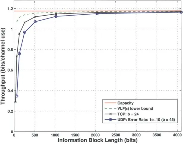
Figure 3-4 illustrates the bounds in (3.35) and (3.36). In this example, C ~ 1.2 bits
per channel use (-ydb = 1 dB), ni = 1, nriU = 4, nm = 8192, and tk = 4096 bits. The corresponding upper and lower bounds are plotted as a function of the information block length per codeword, k. The two cases correspond to two different choices of b, as labeled in the figure legend. The plot shows that the probability of a packet error event is tightly bounded above and below by a nearly constant function of k. The fact the the bounds are nearly constant for fixed b as k varies is not surprising when one considers that, because nIRU,
nm, and tk are held fixed in the example, the number of possible decoding attempts over all codewords in a given packet remains constant as k varies. This can be further understood
by considering the union in (3.5).
In addition to illustrating the upper and lower bounds derived in this section, the curves in Figure 3-4 show the dramatic effect increasing b can have on the reliability of a packet. Also, note that in the example of Figure 3-4, it is assumed that decoding is attempted every 4 complex channel uses. This affects the overall probability of error because the number of opportunities for an undetected decoding error to occur increases as decoding attempts become more frequent. Because of this effect, there is, once again, a tradeoff between the performance a system can achieve, and the overall probability of error. The former would have that the system be configured to attempt decoding as frequently as possible, resulting in a fine tuning of the realized rate to each realization of the channel. The latter would have