Shielded Field Emission EPMA for the Examination of Tranversal and Axial
Sections of Irradiated Fuel Rods.
Renato Restani1, Robin Grabherr1
1 Paul Scherrer Institute, Hot Laboratory Division, Villigen, Switzerland
With the development of the Schottky thermal field emission gun source (FEG) and their application in the electron probe microanalyzer (EPMA) the spatial resolution of elemental mappings in surface investigation has been enhanced and the quantitative analysis of sub-micron particles possible [1, 2]. This is due to the higher beam density allowing analyses at lower accelerating voltage and beam current reducing thus the analysis area and improving the elemental detectability. For the analysis of highly radioactive materials there are for a few decades shielded instruments with a conventional tungsten cathode the current being the Cameca SX100R [3]. There is also a demand for the examination of irradiated materials to deploy the advantages of a FEG source and it was realized by customizing a Jeol 8500F with separation of instrument and control desk by a biological shield for operator protection and internal shields for background reduction of the detectors [4]. Despite the small spectrometers of our EPMA with 140 mm Rowland circle fuel specimens with around an equivalent of 5 GBq 137Cs activity prepared by standard procedure can be quantitatively analyzed down to very low concentrations.
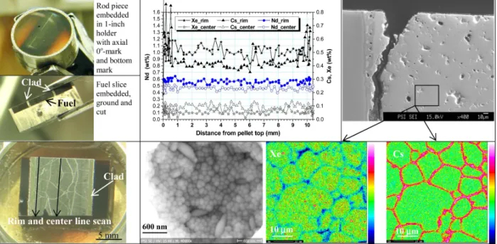
Undesired corrosion deposits precipitating mainly on boiling water reactor fuel rods called CRUD (Chalk River Unidentified Deposits) are made up of 3d metal oxides in the form of iron oxides and spinels of various compositions. For a reasonable measuring time the acceleration voltage cannot be reduced for these elements below 10-12 kV and if the beam current is above 100 nA the improvement in resolution is marginal compared with 15 kV as also indicated in [1]. Nonetheless the lateral resolution of the semi-quantitative X-ray mappings has now considerably been improved to about 0.5 µm for pure iron oxide at the interface to zirconia (figure 1) compared to measurements with a tungsten cathode [5]. It has been straightforward to detect the Fe/Ni bearing second phase precipitates (SPP) in Zircaloy-2 tube by EPMA (figure 2). In general, the SPP in Zircaloy are in the range between 0.05 and 0.3 µm. The migration of volatile fission products to the pellet interfaces are known from axial pin γ--spectrometry. As an EPMA examination over a pellet interface is not possible because of high contamination risk, an axial pellet cut was made up by three embedding steps and longitudinal sectioning to a thin slice of about 0.9 mm thickness (figure 3). Also the pellet top and bottom ends were cut off about 0.25 mm from either interface. Along the axial centre line of a high power 40 MWd/kg burn-up specimen a flat distribution of the volatile Xe and Cs the same as the burn-up monitor Nd is found. Along a line about 0.25 mm from rim there is a clear Cs accumulation at both pellet ends observed and Cs has apparently also precipitated and interacted with the Zircaloy cladding (SE-image at interface). Further there is Cs precipitation at grain boundaries and Xe depletion. SEM quality of the microprobe is also improved as shown on a high burn-up zone with grain subdivision at a pore surface. References:
[1] T Kimura, K Nishida and S Tanuma, Microchim. Acta 155 (2006), p. 175. [2] C Hombourger and M Outrequin, Microscopy Today 21(3) (2013), p 10. [3] CT Walker et al, IOP Conf. Series: Mater. Sci. Eng. 32 (2012) 012028.
[4] R Restani and A Wälchli, IOP Conf. Series: Mater. Sci. Eng. 32 (2012) 012022. [5] A Orlov et al, J. Nucl. Mater. 416 (2011), p. 117.
1820
doi:10.1017/S1431927614010836 © Microscopy Society of America 2014Microsc. Microanal. 20 (Suppl 3), 2014
https:/www.cambridge.org/core/terms. https://doi.org/10.1017/S1431927614010836
[6] The authors acknowledge funding by AREVA NP and KKW Leibstadt AG for this work and the collaboration with the manufacturers JEOL (Germany) GmbH and remX GmbH.
Figure 1. From left to right: Cross-section of fuel rod held together by screws from a sleeve to protect
CRUD. Backscattered electron image (BSE) of CRUD showing Fe rich phase (dark). Fe-map (14.5 x 14.5 µm2) to BSE with max. 40 at% Fe (Fe2O3 from µXRD). Zn distribution (ferritic spinels). HV 12 kV.
Figure 2. From left to right: SE-BSE mixed image of irradiated Zircaloy-2 with grain contrast and
hydride precipitation. X-ray maps of Fe-Ni SPP in the metal (4 x 4 µm2). Condition: HV 12kV, 88 nA.
Figure 3. Left, from top to bottom: Preparation steps of a fuel rod piece to an axial polished pellet
section. Top center and right: Axial quantitative line scan near rim and in center for Cs, Xe and Nd. Cs accumulation at left rim near top pellet interface also seen on SE micrograph at the clad-fuel interface. Bottom: Maps of Xe and Cs with grain boundaries. Micrograph of a pore in a high burn-up fuel.
1821 Microsc. Microanal. 20 (Suppl 3), 2014
https:/www.cambridge.org/core/terms. https://doi.org/10.1017/S1431927614010836