HAL Id: hal-02415305
https://hal.archives-ouvertes.fr/hal-02415305
Submitted on 17 Dec 2019HAL is a multi-disciplinary open access archive for the deposit and dissemination of sci-entific research documents, whether they are pub-lished or not. The documents may come from teaching and research institutions in France or abroad, or from public or private research centers.
L’archive ouverte pluridisciplinaire HAL, est destinée au dépôt et à la diffusion de documents scientifiques de niveau recherche, publiés ou non, émanant des établissements d’enseignement et de recherche français ou étrangers, des laboratoires publics ou privés.
full core analysis of the uh1.2 integral experiment using
idtmethod of characteristics
Jm. Palau, E. Masiello, Jf. Vidal, P. Archier, B. Faure
To cite this version:
Jm. Palau, E. Masiello, Jf. Vidal, P. Archier, B. Faure. recent progess in the vetv of the french apollo3 code 3d full core analysis of the uh1.2 integral experiment using idtmethod of characteristics. PHYSOR 2018, Apr 2018, Cancun, Mexico. �hal-02415305�
RECENT PROGESS IN THE V&V OF THE FRENCH APOLLO3
®CODE:
3D FULL CORE ANALYSIS OF THE UH1.2 INTEGRAL EXPERIMENT
USING IDT METHOD OF CHARACTERISTICS
Jean-Marc Palau
1, Emiliano Masiello
2, Jean-François Vidal
1, Pascal Archier
1and Bastien
Faure
11
CEA, DEN, DER/SPRC/LEPh, Cadarache, F-13108, Saint-Paul-lez-Durance,
Contact:
jean-marc.palau@cea.fr
2
CEA, DEN, DM2S/SERMA/LTSD, Saclay, F-91191, Gif-sur-Yvette
jean-marc.palau@cea.fr
,
emiliano.masiello@cea.fr
,
jean-francois.vidal@cea.fr
,
pascal.archier@cea.fr
,
bastien.faure@cea.fr
ABSTRACT
Within the framework of the V&V of the new APOLLO3® French deterministic code, this paper focusses on its ability of analyzing integral mock-up experiments through IDT flux solver. In the present case, the UH1.2 experiments involving voiding effects in standard PWR UOX lattices are investigated through straightforward 281 groups 3D transport calculations using recent capabilities of IDT solver based on Sn short-characteristics method. Instead of using standard 2D calculations with imposed experimental 𝐵𝑧2we performed directly 3D 281 groups IDT calculations and checked the results against reference continuous-energy Monte-Carlo (TRIPOLI4®) results in a simplified axial configuration. In both cases the IDT solver (with dedicated self-shielding model) shows an excellent agreement with Monte-Carlo results regarding both reactivity and fission rate reference parameters. In particular it is shown that linear short characteristics and refined spatial meshes (3x3x1) are necessary to find the best agreement (less than 1% fission rate and void effect errors). The next step of this work will be devoted to the analysis of the 3D TDT-MOC solver in the same configurations with ad-hoc axial reflector treatment. To remove the limitations in terms of CPU time and memory resources of this kind of calculations, ongoing developments devoted to hybrid shared/distributed parallelization (OpenMP/MPI) are also pointed out.
KEYWORDS: APOLLO3®, V&V, PWR, UH1.2 experiment, IDT, short-characteristics method 1. INTRODUCTION
In order to meet new industrial’s expectations in terms of neutronic calculation accuracy and versatility, CEA launched the APOLLO3® project [1] since 2007. The project’s main purpose is to develop the deterministic multi-purpose neutron transport code APOLLO3®. This is being done at CEA with the support of EDF and AREVA, with the aim of having a better modeling of physical phenomenon of existing reactor cores (including 3rd generation) but also of future reactor concepts (4th generation). APOLLO3® is aiming at replacing the previous 2nd generation of deterministic codes like APOLLO2 [2], CRONOS2 [3] and ECCO/ERANOS [4]. The APOLLO3®-PWR package built with APOLLO3® solvers defines reference calculation schemes associated with a nuclear data library to calculate all neutronic
parameters together with certified biases and uncertainties derived from the VV&UQ process. This VV&UQ process incorporates numerical verification and validation as well as experimental validation leading to uncertainty quantification. The purpose of this paper is to present the capabilities of the IDT solver based on the method of short characteristics to calculate PWR lattice type configurations and integral mock-up experiments such as the UH1.2 EOLE experiments carried out in the 90’s [5]. For the very first time, a one through 3D transport calculation with refined 281 SHEM energy mesh has been carried out. The basic guiding idea was to stress (i.e. assess the performance in terms of CPU/memory behavior) of this solver in the case of a small PWR core dealing with void configurations.
2. DESCRIPTION OF UH1.2 EXPERIMENTS
The UH1.2 experiments are the first part of the EPICURE program carried out between September 1989 and September 1991 in the EOLE facility aiming at validating standard UOx type lattice calculations through dedicated critical state buckling measurements [5]. In a second phase (in 1991) the reference core has been reloaded in order to study local void effects, bowing effects and the introduction of MOx. The geometry and material composition (fuel/cladding/structures) features can be found in specific references (but also in the next MISTRAL program documents [6]).
2.1. UH1.2 configurations
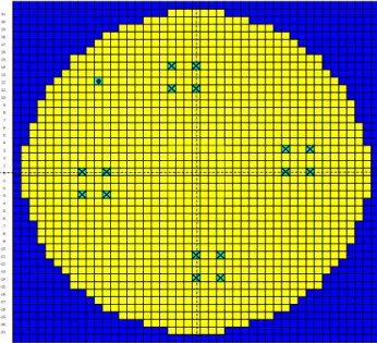
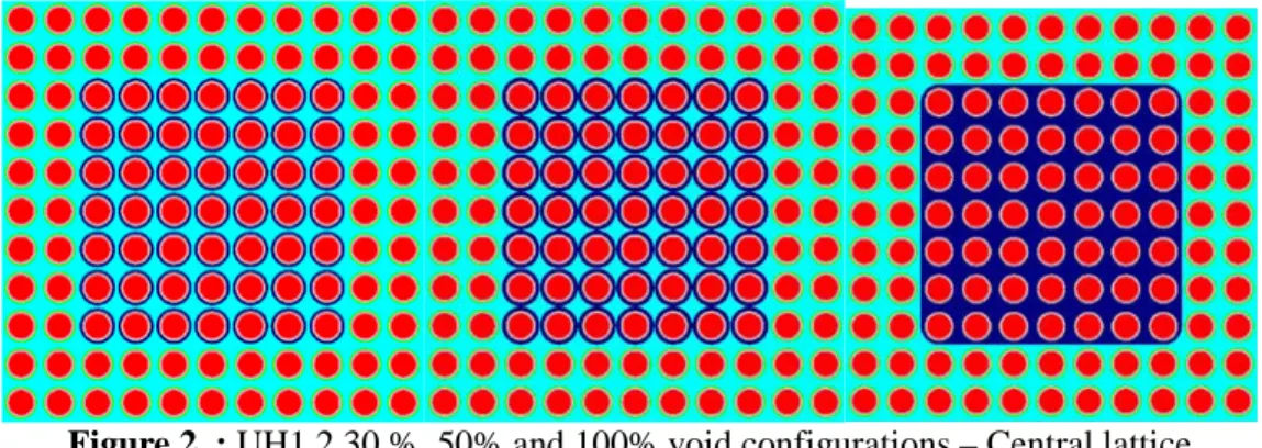
The reference homogeneous core is made of a regular lattice of 1400 UOx standard 3.7% U235 PWR fuel pins (Zircaloy 4 cladded) 80 cm high and 17 stainless steel guide tubes corresponding to the security and pilot control rods. Except the pilot control rods, the UH1.2 core is π/2 radially symmetric (see Figure 1). The radial fission rates measurements were performed in 1989 [5] during the first experimental phase. The void configurations (30% and 50% void) have been done by replacing the 7x7 central AG3 fuel pins cladding by larger diameter ones (colored in dark blue in Figure 2) simulating hot power moderation ratio.
For the 100% void configuration, the central 7x7 lattice has been replaced by a massive AG3 tank built with the same 7x7 cells cross-section. It has to be noticed that this tank has been made with curved corners.
Figure 1. : Radial cross-section of the UH1.2 EPICURE reference configuration (in yellow: pin cell, cross: guiding tubes, dark blue : reflector, red pin cell: control rod)
21 20 19 18 17 16 15 14 13 12 11 10 9 8 7 6 5 4 3 2 1 0 -1 -2 -3 -4 -5 -6 -7 -8 -9 -10 -11 -12 -13 -14 -15 -16 -17 -18 -19 -20 -21 -21 -20 -19 -18 -17 -16 -15 -14 -13 -12 -11 -10-9-8-7-6-5-4-3-2-101 23 45 67 89101112131415161718192021 12 34 56 78 910111213141516171819202122
Figure 2. : UH1.2 30 %, 50% and 100% void configurations – Central lattice
The criticality is reached by adjusting the soluble boron poisoning concentration; the kinetic parameters used in the reactimeter to rely the doubling time with reactivity have been recalculated thanks to JEFF3.1.1 delayed parameters and SHEM-MOC calculations [7].
2.2. Axial bucklings
In the reference UH1.2 configuration, many axial fission rates measurements have been carried out with dedicated 235U, 238U, 239Pu fission chambers located at different radial positions from the center to the periphery of the core and 2 cm high spacing (all along the fissile height, [6]). The axial bucklings are fitted by adjusting by generalized mean squares the measured fission rates to the cosine fundamental function (≅cos(B2
z)), the resulting value being the mean of all these axial values, that is: B 2
z = (1.09 ±
0.01 (2σ)) x 10-3
cm-2
Unfortunately the fission rates axial distributions have not been measured for the void configurations and the required axial bucklings are missing in these cases. Indeed these quantities are very sensitive to boron concentrations and significantly different from void and filled areas. In these situations, the axial bucklings were estimated thanks to 3D TRIPOLI4 calculations and adjustments of the axial fission rates: one from the central area (fission rates integrated over the 7x7 cells) and one coming from a (filled) peripheral area (where the fundamental mode is well established).
Table I shows in the reference configuration the very good agreement between the axial buckling coming from the experiment and from TRIPOLI-4 (1% discrepancy with the 95% experimental confidence interval). In the partially void configurations (30% and 50%), there is a weak difference between the axial buckling coming from the void and filled area. We can use only one value for the following APOLLO3® calculations (with the B1 homogeneous leakage model). In the case of the 100% void configuration, the
axial buckling is 1.6% higher in the void than in the filled area. We will then have to distinguish them. Table I. : Exp. and calc. (TRIPOLI4) axial buckling (10-3 cm-2) in UH1.2 configurations (1σ)
.
Configuration Experimental TRIPOLI-4 Reference 1.09 ± 0.005 1.07878 ± 0.0002 Configuration TRIPOLI-4 void area TRIPOLI-4 filled area
30% 1.07303 ± 0.0002 1.07240 ± 0.0005 50% 1.06798 ± 0.0003 1.06515 ± 0.0006 100% 1.05389 ± 0.0003 1.03763 ± 0.0006
2.3. Fission rates
Fission rates distributions have been measured through integral gamma spectrometry directly performed on the fuel pins. Measurements covered radially the main diagonal and:
- the core-reflector interface for the reference configuration,
- the central region, in particular the 7x7 cells lattice for the void configurations.
In 1989, experimentalists associated 1.5% experimental accuracy (1σ) for the reference configuration including:
- technological uncertainties (material and designed geometry), - fuel pin positions in the core,
- gamma spectometer statistical counting error.
This 1.5% uncertainty has been further considered as overestimated if we refer to the specific studies performed in 1992 during the UH1.4 and UH1.4-ABS experiments, which states values close to 1% (0.8 % in [5]).
For calculation-vs.-experiment comparisons, results have been normalized to several points outside the 7x7 central zone and 3 ranges far from the reflector in order to avoid systematic errors (due to severe perturbations) in the normalization process.
3. TRIPOLI4 MODEL 3.1. Geometry
The 3D TRIPOLI4 geometries 3D of the whole core in the UH1.2 reference and void configurations have been built by using the combinatory mode [8]. Fuel pins are defined precisely as the superposition of fuel pellets (80 cm high) surrounded by AG3 cylindrical cladding (10 cm high). The upper part of the fuel pins has been simplified by cutting the fuel pins at active height and by adding 20cm of water as top/bottom reflector.
3.2. Monte-Carlo simulations and scoring
TRIPOLI4 calculations have run using the 4.9 version of the code on the CEA CCRT HPC machine (128 processors, 24 hours CPU time). One billion histories (100 000 cycles and 10 000 neutrons/cycle) have been simulated to reach 3pcm and 0.2% accuracy, respectively for keff and pin by pin fission rates (scored
axially along 20cm high).
4. APOLLO3 MODELS 4.1. Self-shielding models
The self-shielding models were mainly based on the previous APOLLO2 reference calculation scheme SHEM-MOC. This calculation scheme has been extensively validated against Monte-Carlo calculations through the APOLLO2 and APOLLO3 V&V process [9][10]. Nevertheless, some adaptations have been required for these particular integral experiments.
In particular, the presence of under-moderated void zones have to be considered carefully when dealing with spatial self-shielding effects significantly different in the central zone and require a specific treatment.
Four different calculation patterns have been defined to account these effects and generate 281 groups self-shielded cross-sections for the whole core calculations:
• A single UOx cell (in infinite lattice) to handle fuel pin cells far from the guiding tubes and void regions (cf. figure 4),
• A single UOX but void cell for the fuel pin cells located in the central void zone,
• A 3x3 cluster made of a fuel pin cell surrounded by reflector cells (in that case water poisoned by boron, cf. figure 4),
• A 5x5 cluster made of a guiding tube (control pin cell) in the center surrounded by the so-called “F” (for Face) fuel pin cell , and “A” (for Angle) fuel pin cell and a ring of standard (“asymptotic”) fuel pin cells (cf. Figure 5),
• A 13x13 cluster made of 7x7 void fuel pin cells in the central region surrounded by 3 rings of filled pin cells (the example of the 30% configuration is given in Figure 5).
Figure 5. : 5x5 control cluster (left) and 17x17 voided cluster (right) patterns
The fuel pins are discretized in 4 concentric rings and self-shielding regions (with surfaces equaling 50%, 30%, 15% and 5% of the pin cross-section from the center to the periphery). The LJ (Livolant-Jeanpierre) self-shielding model based on multigroup and homogeneous equivalences is used with the SHEM-MOC recommended options [9].
4.2. IDT models
As indicated in the introduction, the V&V campaign of the first APOLLO3 version (1.2) has been extended to the UH1.2 integral experiments with a special focus on the IDT solver (the TDT-MOC solver is being also investigated but will not be presented here). Indeed the main objective of this V&V phase was to evaluate the feasibility of a pin-by-pin straightforward transport calculation with a fine 281 groups energy mesh (SHEM). As this type of calculation has never been done in the past, it was particularly necessary to stress this flux solver in terms of CPU time and memory resources as well as its accuracy. The heterogeneous IDT solver is particularly suited for this kind of regular structured geometry but it is also a frame of application for the new 3D TDT-MOC solver recently implemented in APOLLO3 with advanced polynomial characteristics and parallelized acceleration method [11]. This solver is currently compared with IDT and MINARET [12] (another APOLLO3 Sn solver dealing with unstructured geometry) but results will not be presented here.
4.2.1. 3D geometrical model
The 3D core geometry is made of 3 native embedded geometries. The first level is the guiding tube cell, the fuel pin cells (eventually void with the corresponding Al cladding), and a reflector water cell. The second level is defined by slices of assemblies made of 15x15x1 (1.26cmx1.26cmx0.5cm) parallelepiped cells. Once the central part of the core is formed, we complete it by additional elementary water cells according the cylindrical core. Beyond the reflector we defined a void zone.
The third level is the axial definition of the reactor with Cartesian meshes that is 18.90cmx 18.90cmx0.5cm slices.
Once constituted the whole core geometry is made of 34 assembly slices leading to: • 1 576 760 spatial nodes,
• 2 048 625 surfaces between pin cells, • 675 000 Cartesian elementary cells,
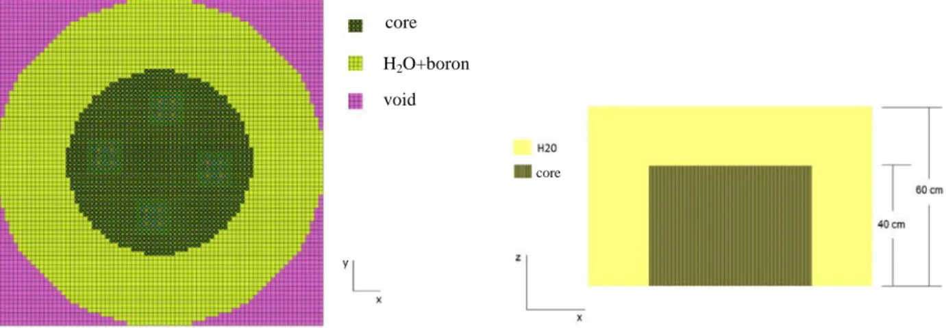
Note that we used the volume cell mesh for the IDT flux calculation is the same than the self-shielding model (6 rings, no sector). This model is sufficiently explicit to describe the fuel pins and does not require any particular homogenization procedure. Figure 6 shows respectively XY (radial mesh) and XZ cross-sections of the IDT geometry.
Figure 6. : Radial (left) and axial (right) cross-section of IDT geometry 4.2.2. Boundary conditions
For sake of simplicity and CPU time savings, the XY axial plan symmetry has been considered with specular reflective condition imposed in the Z mid-plan and vacuum in the upper part (beyond the 20 cm axial reflector). We should also apply π/2 radial symmetry to reduce the radial meshes but this has not been done to stress the IDT solver in all the operating conditions where symmetry properties are no along satisfied due to dissymmetric control rod insertions.
4.2.2. IDT options
The characteristics method is generally based on a polynomial spatial discretization of sources within the calculation cell and angular fluxes all along the 3D cell frontiers [13].
With the IDT solver, the spatial polynomial development is constant, linear or bilinear for sources and angular fluxes [14][15]. The spatial-angular sweeping goes from one surface to another perpendicular to each angular direction. Inner and outer power iterations have been speeded up thanks to the Coarse-Mesh Finite Differences (CMFD, [15]) method using the same 281 energy groups and homogeneous cells (globally 675 000 Cartesian meshes). The angular sweeping and inner iterations have been parallelized using the OpenMP library.
The convergence criteria are defined as follows: • 5 pcm for keff,
• 50 pcm for fission sources
• 5 pcm for angular and spatial flux moments (integrated over each cell).
In this study 3 calculations and (spatial/angular) discretizations have been tested as defined in Table II. It is important to mention that the axial spatial discretization has been reduced to 2cm/mesh (instead of 0.5 cm) when using linear characteristics.
core H2O+boron
void
Table II. : IDT calculations and spatial/angular discretization
Calculation 1 Calculation 2 Calculation 3
Source/flux constant constant linear
Scattering anisotropy P1 P3 P1
Angular quadrature S8 Level-symmetric S12
Tchebychev-Legendre
S8 Level-symmetric
Spatial mesh 2x2x1 4x4x1 4x4x1
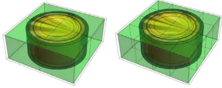
Figure 7 illustrates two types of surface meshes used for the HCC (Heterogeneous Cartesian Cells), respectively 2x2x1 and 4x4x1. The same surface discretization has been applied to the reflector cells.
Figure 7. : 2x2x1 and 4x4x1 pin cell meshes used with IDT solver
All calculations have been performed on CEA/DEN cluster using 20 threads one node 2x10-proc Intel(R) Xeon(R) E5-2680 V2 2.80 GHz sharing 256 GB memory. 8 threads have been used for angular discretization and 20 threads for the CMFD equations resolution.
5. 3D FULL CORE RESULTS
C/E comparisons involved TRIPOLI-4 (version 4.9) Monte-Carlo code and APOLLO3 (version 1.2) deterministic code with the adapted calculation presented previously. The main objective of this study was to assess the ability of APOLLO3 and its Sn solver IDT to deal with mock-up integral experiments
and 3D transport analysis. We will present here the 3D IDT results checking APOLLO3 against TRIPOLI4 (similar 2D IDT calculations with imposed axial buckling were also compared to experiment). 5.1. Reactivity and void effects
In this V&V phase we defined from the experiment a numerical benchmark by simplifying the geometry to make the APOLLO3 against TRIPOLI4 comparisons easier. In fact the radial and axial reflector is modelled in both cases with water without any radial and axial structures. This allowed focusing on APOLLO3 vs. TRIPOLI4 flux calculations more than self-shielding of reflector material and non-regular structures.
Except for the fuel self-shielding models detailed in the previous sections the main differences between the two codes lie on the 3D Monte-Carlo or IDT flux calculations. We can then compare the different IDT calculations (1, 2 and 3) described in the previous section and assess which kind of spatial mesh and angular directions are required in void and reference UH1.2 experiments.
Due to large time consuming calculations (1.5 days for calculation 1 and ½ week for calculations 2 and 3), we focused mainly on the reference and 100% void configuration. The following table summarizes APOLLO3 and TRIPOLI4 results regarding the residual reactivity (keff) and void reactivity effects:
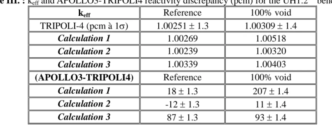
Table III. : keff and APOLLO3-TRIPOLI4 reactivity discrepancy (pcm) for the UH1.2 “benchmark”
keff Reference 100% void
TRIPOLI-4 (pcm à 1σ) 1.00251 ± 1.3 1.00309 ± 1.4
Calculation 1 1.00269 1.00518
Calculation 2 1.00239 1.00320
Calculation 3 1.00339 1.00403
(APOLLO3-TRIPOLI4) Reference 100% void
Calculation 1 18 ± 1.3 207 ± 1.4
Calculation 2 -12 ± 1.3 11 ± 1.4
Calculation 3 87 ± 1.3 93 ± 1.4
In the reference case, a very good agreement is found between APOLLO3 and TRIPOLI4 for all IDT calculations. In the void case, IDT results are significantly improved by calculation 2 and 3 for both reactivity and void effects as pointed out in Tables III and IV. This is mainly due to the spatial mesh refinement which yields a better treatment of void heterogeneities and core/reflector interface.
Table IV. : keff and APOLLO3-TRIPOLI4 void reactivity effect discrepancy (%) for the UH1.2
“benchmark”
Configuration 100% void Void reactivity effect (pcm ±1σ) -2266 ± 50 APOLLO3-TRIPOLI-4 100% void
Calculation 1 -8.4 ± 2.2 %
Calculation 2 -1 ± 2.2 %
Calculation 3 -0.6 ± 2.2 %
As shown here, IDT calculation 2 and 3 lead to significant gain (10 times better) on void reactivity effect, the discrepancy being reduced inside the 1σ experimental uncertainty. It has to be noticed that the slight overestimation of void reactivity effect was also observed in APOLLO2 SHEM-MOC previous calculations.
5.2. Fission rates
The (APOLLO3-TRIPOLI4)/TRIPOLI4 ((AP3-T4)/T4) fission rates discrepancy map (axially integrated in the radial measurement location) are presented hereafter (Figure 8 and 9). They are normalized to: - 25 central fuel pins in the reference configuration,
- 4 fuel pins located in the (-7,-7), (-9,-9), (-11,-11) and (0,-7) coordinates in the 100% voided configuration.
In the case of the reference configuration we reported also in the table:
- the Mean (APOLLO3-TRIPOLI4)/TRIPOLI4 ((AP3-T4)/T4) discrepancy in the two relevant zones: the central zone where the fundamental mode is well established and the peripheral zone at the interface between the core and the reflector (3 last rings),
- the Root Mean Square (RMS),
Table V. : (AP3-T4)/T4 fission rates discrepancy for the UH1.2 “benchmark” reference configuration (mean, max and RMS)
(AP3-T4)/T4 % Mean RMS Max Min
IDT Calculation 1 (central zone) 0.0% 1.3% 3.6% -1.4%
IDT Calculation 3 (central zone) 0.2% 0.9% 3.8% -2.7%
IDT Calculation 1 (core/reflector interface) 13.5% 1.4% 14.6% 11.3%
IDT Calculation 3 (core/reflector interface) 1.1% 0.4% 1.9% 1.0%
Figure 8. : (AP3 -T4)/T4 fission rates discrepancy (%) in the UH1.2 reference configuration: calculation 1 (left) and calculation 3 (right)
Calculation 1 gives satisfactory results in the central zone of the core (along the 21 diagonal pin cells between the (-10,-10) to (10,10) coordinates the RMS is around 1% with 1.6% max error) but poor results close to the core/reflector interface with discrepancies higher than 10%. As a relevant point, this discrepancy is completely cancelled with calculation 3 while calculation 2 does not give a substantial improvement. This shows clearly that the constant source and flux interface IDT approximate is not sufficient to model the flux shape and thermal flux increase close to the reflector.
As stated in Table VI and Figure 9, we observe that calculation 3 lead to the same improvements of reactivity and fission rate calculations in the case of the voided configuration. Actually the improvement of fission rates occurs not only at the core/reflector interface but also in the central void region where the discrepancy is divided by a factor of 2 or 3 leading to maximum errors which do not rise 5%.
Table VI. : (AP3-T4)/T4 fission rates discrepancy for the UH1.2 “benchmark” void configuration (mean, max and RMS)
(AP3-T4)/T4 % Mean RMS Max Min
IDT Calculation 1 (filled area) 0.2% 2.4% 7.8% -2.1%
IDT Calculation 3 (filled area) 0.4% 0.3% 1.1% -0.1%
IDT Calculation 1 (void area) 9.6% 0.7% 10.3% 8.3%
IDT Calculation 3 (void area) 3.1% 1.2% 4.6% 1.4%
IDT Calculation 1 (core/reflector) 7.8% 0.0% 7.8% 7.8%
IDT Calculation 3 (core/reflector) 0.0% 0.0% 0.0% 0.0%
14,3 14,6 14,3 11,3 14,7 14,1 -7,3 15,2 14,1 9,5 14,8 11,2 5,2 2,9 1,6 0,8 0,3 -0,1 -0,4 -0,7 -0,9 -1,1 11,3 -1,2 14,3 -1,3 14,4 -1,4 14,3 1,3 1,5 1,4 1,5 0,9 1,1 1,9 0,6 1,2 0,2 1,0 1,1 0,2 0,2 0,2 0,1 0,1 0,1 -2,7 0,1 0,1 0,1 1,3 0,1 1,3 0,1 1,2 0,1 1,3
Figure 9. : (AP3 -T4)/T4 fission rates discrepancy (%) in the UH1.2 voided configuration : calculation 1 (left) and calculation 3 (right)
6. CONCLUSIONS
This paper shows the ability of APOLLO3 IDT flux solver to analyze integral mock-up experiments such as the UH1.2 experiments carried out in the EOLE facility through transport theory and straightforward 281 groups core calculations. 3D IDT calculations showed that, due to strong heterogeneities (voided configurations and core/reflector interface), refined axial/radial and angular discretizations are necessary to give high quality results for both reactivity and fission rates. Hence linear characteristics improved significantly fission rate calculations and lead to a factor 2 gain in accuracy compared to constant characteristics (using the S8 level-symmetric angular quadrature). Finally we get less than 100 pcm
(reactivity) and 1% RMS (fission rates) discrepancies compared to reference continuous-energy Monte-Carlo TRIPOLI4 calculations.
To reduce computation time and memory resources which are particularly important in this case, several developments are identified. First the introduction of cartesian mesh in the reflector to model more correctly the core/reflector interfaces (radially and axially) and consequently the use of non-conformal cartesian mesh with the IDT solver (this development will be available in the next APOLLO3 version). Secondly the use of spatial and angular parallelization with both shared and distributed memory (the IDT calculation requires in certain cases more than 512 Gb memory). An IDT prototype version based on Domain Decomposition method and hybrid OpenMP-MPI parallelization has been successfully tested in the case of a real full 3D PWR core [16][17]. By using 20 nodes with 20 threads per node the memory consumption has been reduced to 31 Gb per node. The third issue lies on handling 3D self-shielding calculations in particular for the axial reflector constituted of non-conformal structures such as assembly plugs or vessel containers.
To summarize, we highlighted the APOLLO3 IDT capabilities to analyze, through 3D pin-by-pin fine mesh transport calculation, integral experiments such as UH1.2. We also pointed out some limitations of this kind of calculations which need advanced parallelization and acceleration techniques to enable few hours’ simulations and less than 100 Gb memory requirements with the very last PC generation.
ACKNOWLEDGMENTS
APOLLO3® and TRIPOLI-4® are registered trademark of CEA. We gratefully acknowledge CEA, AREVA and EDF for their long term partnership and their support. We would like to thank also the APOLLO3® development team for their efforts in implementing the models described here.
7,8 1,6 -0,1 -1,8 0,0 -2,0 -2,1 0,0 -1,5 -1,5 -1,5 -1,5 -1,5 -1,7 3,4 3,2 2,9 2,2 -0,1 10,3 10,2 9,3 8,3 10,1 9,8 9,1 10,0 9,9 10,0 0,0 -0,1 0,0 0,3 0,5 0,4 0,1 0,8 0,7 0,6 0,5 0,3 1,1 1,0 0,7 0,8 0,4 2,7 2,5 1,7 1,4 3,5 3,1 1,9 4,3 4,0 4,6
REFERENCES
1. D. Schneider, F. Dolci, F. Gabriel, J. Palau, M. Guillo and B. Pothet, “APOLLO3®: CEA/DEN Deterministic Multi-purpose code for Reactor Physics Analysis” Proceedings of PHYSOR 2016 conference proceeding, Sun Valley, USA, May 1-5, 2016.
2. R. Sanchez, J. Mondot, Z. Stankovski, A. Cossic and I. Zmijarevic, “APOLLO2: a user oriented, portable, modular code for multigroup transport assembly calculations”, Nuclear Science and Engineering, pp. 352-362, 1988.
3. J.-J. Lautard, C. Magnaud, F. Moreau and A. Baudron, “CRONOS2: un logiciel de simulation neutronique des coeurs de réacteur”, Technical Report, Saclay, France, 2000.
4. G. Rimpault et al., «The ERANOS code and data system for fast reactor neutronic analyses,» PHYSOR 2002, Seoul, South Korea, October 7-10, 2002.
5. J. Mondot, J.C. Gauthier, P. Chaucheprat, J.-P. Chauvin, J.P., C. Garzenne, J.-C. Lefebvre, A. Vallee, “Epicure: an experimental programme devoted to the validation of the calculational schemes for plutonium recycling in PWRs”, 593 p; 1990; p. VI.53-VI.64; SFEN International Conference on the Physics of Reactors: Operation, Design and Computation; Marseille (France); 23-27 Apr 1990
6. S. Cathalau, J.C. Cabrillat, J.P. Chauvin, et al., “MISTRAL: An Experimental Programme in the EOLE Facility Devoted to 100 % MOX Core Physics”, Proc. Int. Conf. on Physics of Reactor; Physor'96, Mito, Japan, Sept. 16-20,1996, Vol. H, p.84 (1996).
7. A. Santamarina and al., “APOLLO2.8 : A Validated Code Package for PWR Neutronics Calculations” in Advances in Nuclear Fuel Management IV (ANFM 2009), Hilton Head Island, South Carolina, USA, April 12-15, 2009.
8. E. Brun et al., “TRIPOLI-4®, CEA, EDF and AREVA reference Monte Carlo code” Annals of Nuclear Energy, vol. 82, pp. 151-160, 2015.
9. J.-M. Palau et al., “Recent Advances in the V&V of the New French CEA APOLLO3® Neutron Transport Code : Benchmarks Analysis of the Flux Solvers” PHYSOR 2014, Kyoto, Japon, September 28 - October 3, 2014.
10. J.-M. Palau et al., “Recent Progress in the V&V of the New CEA APOLLO3® code : Advanced SFR/LWR Assembly Calculations”, PHYSOR 2016, Sun Valley, Idaho (USA), May 1-5, 2016. 11. R. Sanchez and A. Chetaine, "Synthetic acceleration for a 2D characteristic method in non regular
meshes" in M&C 1999, Madrid, Espagne, September 27-30, 1999.
12. J.-Y. Moller, J.-J. Lautard and D. Schneider, "MINARET, a deterministic neutron transport solver for nuclear core calculations" in M&C 2011, Rio de Janeiro, Brésil, May 8-12, 2011.
13. I. Zmijarevic, "Multidimensional Discrete Ordinates Nodal and Characteristics Methods for APOLLO2 Code," Proc. Mathematics & Computation, Reactor Physics and Environmental Analysis in Nuclear Applications, Madrid, Spain, September 1999, 705 (1999).
14. E. Masiello, I. Zmijarevic, "Short Characteristics Method for Two Dimensional Heterogeneous Cartesian Cells," Int. Top. Mtg. Advances in Reactor Physics, Proc. of Int. Conf. PHYSOR'06, Vancouver, Canada, September 12-15, 2006.
15. E. Masiello, B. Martin and J.-M. Do, "Domain Decomposition and CMFD Acceleration Applied to Discrete-ordinates methods for the solution of the Neutron Transport Equation in XYZ Geometry," in International Conference on Mathematics and Computational Methods Applied to Nuclear Science and Engineering, Rio de Janeiro, Brazil, 2011.
16. R. Lenain, E.Masiello, F. Damian, R.Sanchez, "Domain Decomposition Method for 2D and 3D Transport Calculation Using Hybrid MPI/OpenMP PArallelism", SNA M&C 2015, Int. Conf. on Mathematical Computations, Illinois USA 2015
17. R. Lenain, E. Masiello, F. Damian and R. Sanchez, "Coarse-grained parallelism for full core transport calculations," in Physor2014, Kyoto,Japan, 2014.