HAL Id: hal-03137276
https://hal.archives-ouvertes.fr/hal-03137276
Submitted on 10 Feb 2021HAL is a multi-disciplinary open access archive for the deposit and dissemination of sci-entific research documents, whether they are pub-lished or not. The documents may come from teaching and research institutions in France or abroad, or from public or private research centers.
L’archive ouverte pluridisciplinaire HAL, est destinée au dépôt et à la diffusion de documents scientifiques de niveau recherche, publiés ou non, émanant des établissements d’enseignement et de recherche français ou étrangers, des laboratoires publics ou privés.
First error budget of a deployable CubeSat telescope
Jean-François Sauvage, Noah Schwartz, Sébastien Vievard, Aurélie Bonnefois,
Marie-Thérèse Velluet, Carlos Correia, Frédéric Cassaing, Thierry Fusco,
Vincent Michau, Jean-Claude Krapez, et al.
To cite this version:
Jean-François Sauvage, Noah Schwartz, Sébastien Vievard, Aurélie Bonnefois, Marie-Thérèse Velluet, et al.. First error budget of a deployable CubeSat telescope. SPIE Astronomical Telescopes + Instru-mentation 2020, Dec 2020, Online Only, France. pp.1144330, �10.1117/12.2561697�. �hal-03137276�
First error budget of a deployable CubeSat telescope
J.-F. Sauvage*a,b, N. Schwartzc, S. Vievarde, A. Bonnefoisa, M.-T. Vellueta, C. Correiad, F. Cassainga, T. Fuscoa, V. Michaua, J.-C. Krapeza, M. Ferrarib, I. Laginjaa,b,f
bONERA, 29 avenue de la Division Leclerc, 92322 Châtillon, France; bAix Marseille Univ, CNRS, CNES, LAM, Marseille, France ;
cUK Astronomy Technology Centre, Blackford Hill, Edinburgh EH9 3HJ, United Kingdom d Space ODT, Rua A. C. Monteiro, 65, 4050-014 Porto, Portugal
e National Astronomical Observatory of Japan: Hilo, JP
f
Space Telescope Science Institute, Baltimore, MD 21218, USA
ABSTRACT
The volume available on-board small satellites limit the optical aperture to a few centimetres, which limits the Ground-Sampling Distance (GSD) in the visible to approximately 3 m at 500 km. We present a performance analysis of the concept of a deployable CubeSat telescope. This payload will allow a tripling of the ground resolution achievable from a CubeSat imager, hence allowing very high resolution imaging from Low Earth Orbit (LEO).
The project combines precision opto-mechanical deployment and cophasing of the mirrors segments using active optics. The payload has the potential of becoming a new off-the-shelf standardised system to be proposed for all high angular resolution imaging missions using CubeSats or similar nanosats. Ultimately, this technology will develop new instrumentation and technology for small satellite platforms with a primary mirror size equal or larger than 30 cm.
In this paper, we present the breakdown of the different error sources that may affect the final optical quality and propose cophasing strategies. We show that the piston, tip and tilt aberrations may need to be as small as 15 nm RMS to allow for diffraction-limited imaging. By taking a co-conception approach, i.e. by taking into account the post-processing capability such as deconvolution, we believe these constraints may be somewhat released.
Finally, we show numerical simulation of different solutions allowing the aberrations of the primary mirror segments.
Keywords: High angular resolution, space active optics, Earth Observation
1. INTRODUCTION
To fully reach their potential, many scientific and technological fields (e.g. Earth climate monitoring and protection, civil security or solar system exploration) require a combination of very high-resolution images (spatial resolution) and high revisit rate (temporal resolution). However, combining both high spatial and temporal resolution is at the moment completely out of reach at reasonable costs. Indeed, both requirements can only be achieved simultaneously by using multiple platforms in LEO (Low Earth Orbit) constellation, which requires small individual satellites to lower the cost. However, a small platform (e.g. CubeSat 10cm standards) inherently decreases the maximum optical aperture and degrades the spatial resolution in the image. For instance, a 10cm telescope (maximum aperture size onboard a CubeSat, at experimental level) provides only 3m resolution images from a 500km orbit in visible wavelength (500nm) due to the diffraction limit.
The radical vision of the proposed concept is to go beyond this trade-off and enable both very high spatial resolution and very high temporal resolution onboard CubeSats through the development of a
deployable telescope payload for CubeSat embedding an active optics system driven by artificial intelligence (AI), ensuring the high optical quality required.
On the one hand, this concept offers sub-metric resolution thanks to a 30cm optical aperture deployed and phased in space (0.8m for 500km orbit and 500nm wavelength), on top of the natural photometric capacities and SNR (Signal to Noise Ratio) improvement brought by a large aperture. On the other hand, this concept relies on the low-cost CubeSat standards to ensure the high revisit rate (in a constellation). A 6U satellite of <10kg is sufficient to deploy a 30cm telescope in space. As a comparison, the mass of the SPOT6/7 satellites is 714kg to achieve 1.5m Ground Sampling Distance (GSD). This gain in weight directly translates into a gain in cost and therefore allows to multiply the number of platforms and, in principle, increase the temporal resolution (revisit rate) by a factor 10 to 20. The average number of imaging opportunities per day over one area of interest depends on agility (capacity to off-point rapidly around the CubeSat’s axis - yaw, pitch, roll - during flight), constellation configuration and science mission requirements. The latter will be investigated, and potential configurations of constellation will be proposed during the project.
This concept will be subject to a major perturbation: the thermo-mechanical deformation of the satellite due to different positions with respect to the sun during a 90 minutes orbit. The high optical quality necessary for high angular resolution requires to perform onboard the satellite an autonomous optimization loop to maintain the optical quality, keeping the segmented telescope phased to the few-tens nm level. This will be possible thanks to the development of an onboard Artificial Intelligence (AI) consisting of a wavefront-sensing (WFS) and correction loop.
We propose in this paper to briefly describe the concept and its opto-mechanical design (in section 2) and to develop the optical performance required for such an ambitious concept (in section 3) and present first results of wave-front sensing dedicated to this particular aperture (in section 4), which is a key assessment of the project.
2. SYSTEM CONCEPT AND DESIGN
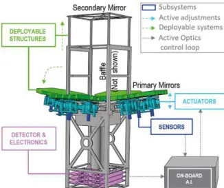
The concept consists of a deployable telescope folded inside a CubeSat standard (the payload volume fits within a 3U volume). The opto-mechanical concept presented here is developed by UK-ATC [1] , and is the base for the HighRes prototype. It is illustrated on Figure 1.
The primary mirror is composed of 4 segments square-shaped of approximately 10cm edge. They are deployable, and motorized with 3 degrees of freedom once deployed (piston, tip and tilt). The respective alignment of the segments one with respect to the others is the key performance to high angular resolution.
The secondary mirror, also deployable, reflects the light down to the detector. The detector provides an image of the observed area.
The embedded real-time computer allows to estimate the phasing residuals from the detector image, and corrects it down to a fraction of wavelength with the segments actuators.
Typically a Field of view of 1x1°, or 8km on Earth from a 500km orbit, in visible wavelength is aimed at.
Figure 1: Simplified illustration of the deployable payload concept: deployable structures (primary & secondary mirrors, baffle), actuators to adjust mirror positions, sensors to measure mirror positions, detector to assess image quality, and onboard AI to control and adjust mirror positions to reach diffraction-limited image quality (i.e. active optics).
3. HIGH ANGULAR RESOLUTION CONSTRAINTS
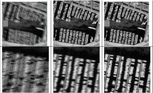
The high angular resolution regime is defined by ESA as a ground resolution. Presenting from any space platform a resolution better than 1m is defined as high (or even very high) angular resolution. In term of optics, this resolution can be reached only by ensuring a perfect propagation of the light through the telescope mirrors down to the detector. How perfect is the crucial question to answer. Typically, reaching the diffraction limit is ensured when the Strehl Ratio reaches more than 80% (Born and Wolf). In the visible wavelengths, this means that the wavefront residual should be less than 40nm RMS. An illustration of the loss of resolution expected from a deployed telescope is shown on the Figure 2. A phasing based only on a very good mechanical precision of the deployement at 2 microns, is shown in left column. The corresponding image of the Vieux-Port of Marseille clearly shows the loss of performance, already visible on the large Field of view image of 1km. A phasing at a sub-wavelength precision of 200nm is not enough to provide the ultimate resolution, but already provides a good photometric sensor. Only a phasing smaller than the diffraction limit (here taken at 20nm RMS) really to reach the full resolution of the imager.
This criterion, based only on static wavefront aberrations is nonetheless not sufficient to specify the performance of this concept. A space platform being subject to vibrations, pointing error, cyclic thermal deformation, a more thorough criterion set has to be defined.
Unphased telescope 2micron RMS residual Partial phasing 200nm RMS residual Correct phasing 20nm RMS residual
Figure 2: simulation of ground images taken by a deployed telescope onboard a CubeSat. A simple piston, tip and tilt residual is considered on the primary segments. The corresponding images are shown in 1km field of view (top) and central 100m field of view (bottom). Different phasing residuals are considered, going from 2microns (left), 200nm (center) and 20nm (right).
The list of criterion has not been detailed here. We considere only in this paper the Strehl Ratio criterion. A further work should include the following criterion :
Quality criterion of a High Angular Resolution system:
• Full Width Half Maximum => This criterion is directly linked to the final resolution • Strehl Ratio => linked to an SNR criterion
• Residual jitter (PSF stability) => This criterion gives a constraint on the temporal aspect of the light of sight. At slow timescale (pointing) as well as fast timescale (jitter)
We propose here some classical values for these three criterion in the case of our concept. These numbers are based on a theoretical high angular resolution system, and is not consolidated by the specific needs expressed by a scientific mission.
As a reminder, the diffraction angle of a 0.3m aperture in visible wavelength of 600nm is 0.4 arcsec.
Typical acceptable errors for a diffraction limited system
• OPD error < 40nm RMS residual • Residual jitter < 0.04 arcsec (goal 0.02 arcsec) • Drift during an exposure < 0.04 arcsec (goal 0.02 arcsec)
Of course, the performance of 40nm RMS can only be reached by an active system. In particular, the phasing of the segments after deployement is a critical parameter to optimize. Today, the residual
OPD that can be reached with only relying on the mechanical precision is around 2 to 5 microns RMS. This residual can be partially (if not totally) compensated by actuating the segments, and re-aligning them in orbit by an active optics system. This compensation is however not perfect. It is limited by the usual errors of an active (or adaptive) optics system: the imperfect measurement of the residual, the resolution of the actuator, the delay due to varying deformation count amongst the limits of the method.
On top of this active optics residuals, some other error sources may degrade the final resolution. We propose here to list these sources.
Category Definition Source Comment
Intrinsic optical quality
Optics quality
Manufacturing Low order residual due to the process of manufacturing of the segments and optics of the system
Polishing Polishing errors, mainly high orders
Initial alignement (in lab environnement)
The optical residual of the optical elements after the alignement of the system in laboratory (apart from the segments phasing)
Ground to space degradation
launch impact Deformation of the intrinsic optic quality due to the launch space environnement Deformation of the
intrinsic optic quality due to the difference of environnement
between ground and space
Observation environment
Thermal deformation Effect of the thermal deformation on the system optics
Drifts of line of sight Effect of the pointing error of the system
Segments-related optical quality Differential piston residual between segments Residual of phasing, after active optics action
Differential tip-tilt residual between segments
Residual of orientation after active optics action
between segment curvature and telescope curvature, in term of wave-front error Deployment-related optical quality Secondary mirror deployment precision Effect of secondary mirror deployement on the wave-front error Table 1: Error sources at the origin of a degradation of the high angular resolution.
The list shown in Table 1 illustrates the numerous origin that might eventually degrade the resolution of our concept. In the absence of any system analysis, we propose to split the 40nm OPD tolerance ensuring a 80% Strehl Ratio within each term of this list, equally. Considering that these 8 error sources listed here are independent error sources, this translates into a 40/sqrt(8) = 15nm RMS for each term.
Of course, a further analysis of performance should help to illustrate potential correlation between these error terms and refine this rough distribution. This system analysis should also balance this error budget, by releasing constraints on some terms difficult to reach and tighten the constraint on easily accessible terms.
In this list, some terms are considered as residuals after active optics correction (differential phasing between segments), while some others are considered as direct degradation and uncorrectable by the active optics system. In particular, the thermal degradation leading to deformation intrinsic to the segment (as curvature errors) are completely out of sight of the active optics chain and will directly impact the final resolution.
In the next session, we present a first result of the wave-front sensing capacity of the concept.
4. WFS: BASELINE STRATEGY FOR PHASING SEGMENTS
The active optics system is based on a wave-front sensor function, allowing the measurement of the optical aberrations residual. This function is ensured inside a closed-loop process, consisting of a real-time correction of the wave-front by the active segments.
We make the assumption that the system is able to point a star during the phasing operation, in order to illustrate our baseline strategy for WFS. Further development based on the use of A.I. algorithms should allow to perform this operation on extended ground images.
In this paper, we considere only the residual coming from the differential phasing errors between the primary mirror segments. Piston, tip and tilt are the only perturbation terms. The amplitude of the error terms varies between micrometers (after the telescope deployment) down to a few nanometers (during optimized closed loops, ensuring the final optical quality). Such a large range drives us to considere different solutions to ensure the capture, rough phasing and fine phasing. This procedure is based on the proposition of F. Cassaing for space segmented aperture systems.
Step Capture range Precision specification
Telescope initial deployment
- Within the detector
Coarse phasing Detector field of view Sub-wavelength
Fine phasing Few Wavelength 15nm RMS
The First step of phasing consists in the initial deployement of the telescope in orbit. The precision of this step has to drive the final phasing of the segments so that the image of each segments falls withing the detector field of view. With the definition of our system, this precision should be better than 15 milliradians for an 1° field of view detector. This precision looks achievable according to the regular results demonstrated on the HighRes prototype by N. Schwartz (this conference).
The second step consists in a coarse phasing of the segments, orientating them toward the same light of sight. The capture range of this method, using by instance the ELASTIC method [2] , is limited only by the field of view of the detector. The ultimate precision is limited (amongst other terms) by the flux of the star. As demonstrated on the simulation result of Figure 3, a phasing residual smaller than the wavelength can be reached with a star flux higher than 5e4 photons in the image. This flux can be reached by example with a star of magnitude 6 in a 1 second exposure time. Of course, with a higher flux (due to brigher star or cumulated images), a better resolution can be reached.
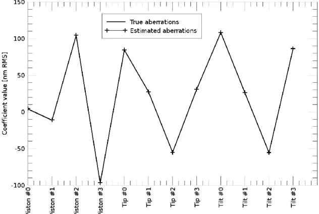
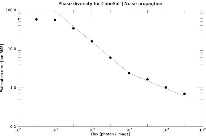
The last step consists in a fine phasing of the segments, using a phase-retrieval focal-plane wave-front sensor as phase diversity [3]. This wave-wave-front sensor is based on using a pair of focal-plane and defocused image to produce an estimate of the aberrations in the image (as illustrated on Figure 5). This method relies on the modelization of the image formation in the focal plane, taking into account the pupil and detector geometry, as well as the optical system characteristics (image sampling, pixel response…). The behaviour of this wave-front sensor is well-known. The Figure 5 illustrates the pahse diversity measurement of the 12 degrees of freedom of our system, piston tip and tilt for each segments. For a error-free model, the estimation is only limited by the noise in the images. The Figure 6 shows the measurement error of phase diversity with respect to the flux of the star used to perform the calibration. A precision of 15nm RMS is reached for a star flux higher than 1e4 photons. Such a flux can be reached by a 1 second exposure time of a 8th magnitude star.
Figure 3: Measurement errors of the ELASTIC method, implemented on the four-segments apertures proposed in our concept. A typical sub-wavelength regime is reached for flux higher than 5e4, typically reached with star magnitude higher than 6 and a 1 second exposure time.
Figure 4: pair of images used to perform phase diversity. Left : in-focus image. Right : out-of focus image. The pure defocus considered might be produced by a movable secondary mirror, or approximated by tilting the segments.
Figure 5: Example of phase diversity estimation of the 12 degrees of freedom of the concept : piston, tip and tilt on the four segments. In this case, the image formation model is perfect (we talk about inverse crime) and the estimation is only limited by the noise in the images.
Figure 6: Measurement error of phase diversity, with respect to the flux of the star used to perform the measurement. 15nm RMS residual can be reached with a star flux higher than 1e4 photons / image, which can be reached with star magnitude higher than 8 and an exposure time of 1 second.
5. CONCLUSION / PERSPECTIVES
In this paper, we have proposed an error budget breakdown for a deployable telescope onboard a CubeSat. This budget is a first draft, based on rough assumptions. We have demonstrated that in order to reach a diffraction limited regime, defined as a Strehl Ratio > 80%, a 15nm residual should be reached on the differential piston, tip, tilt on the segments. An active optics function is mandatory, to measure and correct for the large mis-alignement errors provoked by the deployment. We have proposed a strategy for measuring the differential aberrations between segments, assuming pure piston tip and tilt modes, and demonstrated that a 3 steps process based on deployment, coarse phasing, and fine phasing looks accessible through the use of geometric-based method (ELASTIC) and focal-plane wave-front sensing (Phase diversity).
Of course this work is a first try to the optimization of a space deployable telescope onboard a CubeSat. In the future we have to refine the error budget by a thorough system analysis. A particular case has to be brought to the temporal variation of aberrations, which will require the development of an thermos-opto-mechanical model describing the temporal evolution of the aberrations during a low orbit.
On top of this system analysis, we have to analyse the performance of the active optics loop in more realistic regime. Firstly, by including some uncorrected high orders aberrations coming from the identified terms of the error budget. Secondly, by including the aberrations varying with time. These include the thermal degradation, drift in the line of sight, jitter. The performance of the proposed baseline has to be revisited with this enhanced environment.
We know that the proposed baseline suffers from an intrinsic limitation. The strong assumption of observing a bright star to perform the WFS is difficult for a CubeSat. The agility of such small platform is very limited, and might not be able to rotate 180° toward the Earch surface fast enough to ensure that the thermal aberration have not degraded the optical quality during this rotation. We propose to develop the I.A. algorithm to directly perform the WFS on extended Earth scenes. I.A. approach might also improve the difficulty of a comple image formation model due to specific detector (TDI).
REFERENCES
[1] High-resolution deployable CubeSat prototype, N. Schwartz et al, SPIE 2020 (This conference)
[2] S. Vievard, F. Cassaing, L. Mugnier. Large amplitude tip/tilt estimation by geometric diversity for multiple-aperture telescopes. Journal of the Optical Society of America. A Optics, Image Science, and Vision, Optical Society of America, 2017, 34 (8), pp.1272-1284.
[3] A. Blanc, L. M. Mugnier, and J. Idier. Marginal estimation of aberrations and image restoration by use of phase diversity. J. Opt. Soc. Am. A, 20(6):1035–1045, 2003