HAL Id: cea-02280910
https://hal-cea.archives-ouvertes.fr/cea-02280910v2
Submitted on 3 Mar 2020
HAL is a multi-disciplinary open access
archive for the deposit and dissemination of
sci-entific research documents, whether they are
pub-lished or not. The documents may come from
teaching and research institutions in France or
abroad, or from public or private research centers.
L’archive ouverte pluridisciplinaire HAL, est
destinée au dépôt et à la diffusion de documents
scientifiques de niveau recherche, publiés ou non,
émanant des établissements d’enseignement et de
recherche français ou étrangers, des laboratoires
publics ou privés.
Carolynn Bernier, François Dehmas, Nicolas Deparis
To cite this version:
Carolynn Bernier, François Dehmas, Nicolas Deparis. Low Complexity LoRa Frame Synchronization
for Ultra-Low Power Software-Defined Radios. IEEE Transactions on Communications, Institute of
Electrical and Electronics Engineers, In press, �10.1109/TCOMM.2020.2974464�. �cea-02280910v2�
Abstract—Low power wide area (LPWA) wireless networks based on the LoRa physical layer have attracted huge attention in recent years, both from industry and from academic researchers. While this rising popularity is due to this technology’s demon-strated effectiveness and low cost, unfortunately, due to their complexity, the timing and frequency synchronization algorithms required to detect LoRa-modulated frames, in the context of minimum sampling rate optimum receivers, have received little attention. The aim of this paper is to fill this gap and describe how robust frame detection can be performed while focusing on minimal complexity implementations of the proposed algorithms. The ultimate goal is to propose frame detection techniques applicable to recently proposed ultra-low power software-defined receivers.
Index Terms—Chirp modulation, frequency shift chirp modu-lation (FSCM), Internet of Things (IoT), LoRa, low power wide area networks (LPWAN)
I. INTRODUCTION
Low power wide area (LPWA) wireless networks are gain-ing large-scale industrial acceptance and enablgain-ing new smart applications in verticals such as transportation, health, industry and agriculture. With an expected shipment of 350 million compatible nodes in 2022, and with a large number of com-patible gateways already deployed on a global scale, LoRa (short for “Long Range”) is an increasingly popular modu-lation scheme for LPWA communications [1]. This growing popularity has, in its turn, spurred a quick reaction from the research community. Indeed, a recent review of research work published from 2015 to September 2018 and concerning either LoRa or LoRaWAN, a medium access control (MAC) communication protocol based on the LoRa physical layer, shows that approximately 2000 papers have been published in this short time, clearly demonstrating the importance of this new technology to the research community [2]. A non ex-haustive list of LoRa and LoRaWAN-based research includes areas such as physical layer evaluation in the presence of interference, coverage tests, capacity evaluation, models for network level simulators and applications and deployments.
The fact that LoRaWAN’s specifications are available in open access has clearly been beneficial to the research com-munity. On the contrary, many details about the LoRa physical layer itself remain trade secrets. However, the importance of LoRa in the LPWA landscape prompted efforts in the IoT research community to reverse engineer the LoRa physical layer and share this information publicly [3][4][5][6]. A better
C. Bernier is a member of the Architectures, Circuits and Embedded Software Department and F. Dehmas and N. Deparis are with the Systems Department of CEA, LETI, Grenoble, France.
understanding of the LoRa modulation format indeed enables new research activities such as the development of new local-ization algorithms, the development of accurate physical-layer models, the evaluation of potential security breaches, and the invention of further physical layer improvements.
Another motivation for gaining a better understanding of the LoRa physical layer is the development of LoRa-compatible demodulation software for recently proposed ultra-low power software defined radios (ULP-SDR) [7][8][9]. Indeed, com-pared to today’s commodity IoT transceivers which are mostly implemented in hardware, software-based wireless transceivers enable the implementation of different physical layers on the same hardware. With the uncertain evolution of LPWA networks and standards, software transceivers also minimize development cost, enable multi-standard and multi-mode ap-plications and future-proof integrated circuit designs. Finally, software transceivers also make it possible to develop precise link quality information extraction algorithms directly within the receiver’s digital baseband [10][11].
Unfortunately, while the rising popularity of LoRa-based technology is clearly due to its accessibility, i.e. low cost and simplicity of deployment, the signal processing required to recover LoRa modulated signals is, on the contrary, relatively complex. Using the terminology proposed in [12], LoRa em-ploys a Frequency Shift Chirp Modulation (FSCM) in which the information is encoded by a frequency shift applied to a constant chirp rate symbol (a chirp is a frequency modulated signal). Before being able to demodulate the received symbols and recover the data, a LoRa receiver must also compensate for sampling, carrier frequency and symbol timing offsets that are due to unsynchronized timing references between the transmitter and the receiver. To date, little work has been published concerning the frame synchronization procedure for FSCM-modulated frames, and for LoRa frames in particular.
The purpose of this paper is to contribute to the under-standing of the preamble and start-of-frame synchronization requirements of FSCM signalling schemes. In view of a potential implementation on an ULP-SDR receiver, the focus of this paper is on low complexity frame synchronization algorithms. In particular, we explain how the use of both up and down base modulated chirps within the frame’s preamble is used to resolve integer symbol timing and carrier frequency offset ambiguity. From this, we deduce the maximum carrier frequency offset (CFO) that can be tolerated by the receiver. We provide simulation and measurement results showing the relationship between number of received preamble symbols and both frame detection performance and fractional CFO estimation error. Finally, we propose several ideas for lowering
the complexity of certain synchronization mechanisms, such as the detection of data sample start time.
This paper is organized as follows: We start in Section II by a mathematical description of the FSCM modulation and its frame synchronization requirements assuming Nyquist rate reception. We also give two fundamental synchronization algorithms. In Section III, we discuss related work on FSCM frame synchronization. Section IV is specifically dedicated to the detection of LoRa modulated frames. Finally, Section V proposes a number of ideas for implementing new, low com-plexity synchronization algorithms for FSCM, in particular in the light of upcoming ULP-SDR transceivers.
II. FSCMMODULATION
Digital communication schemes based on linear frequency modulated (i.e. linear chirp) signals have been in use for many years in applications ranging from military communications to short-range personal area networks [13][14]. While past modulation schemes encoded information either by varying the chirp rate, i.e. the rate at which the RF carrier frequency is varied, between a set of possible values or by using two signals with opposite chirp rates (often named up-chirps and down-chirps), in the LoRa physical layer, the information bearing element is a frequency shift applied at the beginning of each constant rate chirp. Thus, the name frequency shift chirp modulation (FSCM) assigned to the LoRa modulation by [12].
The FSCM modulation employed in the LoRa signalling scheme is an orthogonal modulation with symbols encoded using a set of N cyclically shifted versions of a base Zadoff-Chu (ZC) sequence. The general expression for ZC sequences is defined as follows [15]: uM[k] = ejπ.M.k(k+1)N , k = 0, 1...N − 1 if N is odd ejπ.M.k2N , k = 0, 1...N − 1 if N is even.
If M and N are relatively prime, i.e. gcd(M, N ) = 1, the auto correlation of a ZC sequence with all N − 1 cyclically shifted versions of itself is zero for all values of n different from zero: RM M[n] = 1 N N −1 X k=0 uM[k]uM[(k + n) mod N ]∗ = ( 1 for n = 0 0 for n 6= 0
In order to simplify the extraction of the modulation value from the set of N cyclicly-shifted versions of a root (also called base) ZC sequence, B[k], it is advantageous to choose M = 1. Adjusting this base sequence such that its normalized frequency covers the span [−0.5, 0.5], we define B[k] as follows:
B[k] = ej2π(2Nk2− k
2), k = 0, .., N − 1 (1)
This signal corresponds to a linear frequency modulated signal with frequency slope, or chirp rate, equal to 1/N and
with an initial normalized frequency of -0.5. N sequences, SN0[k] with N0= 0, .., N − 1, are produced through N cyclic
shifts of B[k]: SN0[k] = e
−jπN0(N0/N −1)B[(k + N
0) mod N ],
k = 0, .., N − 1 In the above equation, the exponential term is necessary to set each symbol’s initial and final phase to zero, enabling a continuous phase modulation. This equation simplifies to [16]:
SN0[k] = e
j2π(k2
2N+k(N0N− 1
2)), k = 0, .., N − 1
If a signalling bandwidth of size BW is allocated to the system, the minimum sampling frequency, fsmin, is equal to
BW .
A. FSCM demodulation in ideal synchronization conditions Assuming perfect time and frequency synchronization, op-timum non coherent demodulation is performed by first mul-tiplying the received symbol SN0[k] by the conjugate of the
base sequence: SN0[k]B
∗[k] = ej2πkN0N , k = 0, .., N − 1
The symbol value N0 is extracted from the resulting constant
frequency signal using an FFT and locating the frequency index, referred to as bin in the following, of the peak value of the FFT magnitude (an operation referred to as argmax). It is shown in [12] that this is the optimal receiver. With N possible symbols, a maximum of log2(N ) bits can be
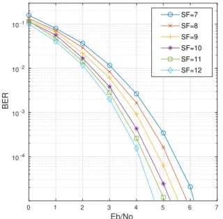
encoded within each symbol. Of course, it is always possible to use symbol redundancy to improve the link robustness, at the cost of information-carrying capacity. The choice of this modulation versus other modulations commonly employed in LPWA communication schemes (such as BFSK) is justified by the high energy efficiency (minimum energy per bit versus noise density, Eb/N o) obtained for high modulation orders, as shown on Figure 2 [17].
B. Nyquist-rate receivers
Differently from the reverse engineering efforts mentioned in the introduction and which employ high sampling rate USRP (Universal Software Radio Peripheral) receivers to capture LoRa-modulated frames (such as in Figure 1), the IoT context requires transceivers designed for ultra-low power consumption. Thus, in practical receivers, in order to minimize power consumption, the down-converted signal is decimated down to its minimum sampling rate fsmin. In addition, both
memory usage and computational complexity of the digital baseband processing algorithms must be kept to a minimum. Finally, received samples must be processed in close to real time in order to minimize delay. The synchronization algo-rithms discussed in this work will focus on low complexity, minimum sampling rate receivers.
Fig. 1. Annotated spectrogram of an example LoRa signal (with settings SF=11, BW=125 kHz) Reproduced with permission from [3].
C. FSCM frame synchronization requirements
Frequency and timing synchronization are difficult to guar-antee in practice due to offsets in the frequency references used by the transmitter and receiver. More precisely, these offsets will result in:
• a carrier frequency offset, CF O, which can be sep-arated into two components: CF Oint and CF Of rac,
which are, respectively, the integer and fractional parts of N × CF O/BW ,
• an initial symbol timing offset, ST O, which can be separated into two components: ST Oint and ST Of rac, • an ambiguity concerning the (optional) header or payload
start time, as discussed in Section V-F,
• a sampling frequency offset, SF O, which, if uncorrected, will generate an incremental symbol timing offset,
• and, potentially, since both the transmitter and receiver’s
quartz-based references are susceptible to drifts due, for example, to changes in temperature (drifts on the order of a few tens of Hz/s are common), a receiver may also have to compensate for changes in the CF O and SF O. If the RF synthesizer and sampling clocks are generated from the same crystal-based reference clock, CF O and SF O will suffer from correlated drifts. This effect can be particularly severe for long frames. Drift compensation methods will not be discussed in this work.
0 1 2 3 4 5 6 7 Eb/No 10-4 10-3 10-2 10-1 BER SF=7 SF=8 SF=9 SF=10 SF=11 SF=12
Fig. 2. Ideal non-coherent FSCM demodulation performance for N = 2SF
and SF = 7, .., 12
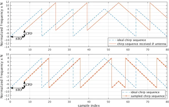
The impact of CF O and ST O is illustrated in Figure 3 in which we observe the frequency component of the received modulated signal prior to sampling and after sampling at a normalized rate of 1/N . First, we observe that CF O will shift the signal out of the receiver’s reception bandwidth, defined by in the interval [−N/2, .., N/2]. Sampling at a normalized minimum rate of 1/N folds the signal back into the receiver’s input bandwidth which, in Figure 3, has the effect of reconstructing complete up-chirps. We observe that CF O (measured in Hz) has an integer and fractional component, CF O = CF Oint+ CF Of rac. In the example of Figure 3,
the signal is received with a CF O (vertical shift) equivalent to 3.5 frequency bins. Both CF Oint and CF Of rac must be
recovered by the synchronization algorithm. Indeed, as dis-cussed in [18], at low signal to noise ratios (SNR), CF Of rac
will shift the FFT outputs between two integer frequency bins, resulting in demodulation errors.
Next, in the absence of synchronization, after sampling, the receiver has no way of identifying the start of the received sequence, resulting in an ST O consisting of an integer number of samples, ST Oint (with ST Oint < N ) plus a fraction of
a sample, ST Of rac. In the example of Figure 3, the signal
is received with an ST O (horizontal time shift) equal to 7.2 samples. Recovering ST Oint is mandatory for correct
alignment to the modulated symbols and compensating for ST Of rac is necessary for concentrating the symbol energy
within a single FFT bin. Most importantly, we observe that, simply by extracting the start times of the reconstructed up-chirps, it is impossible to resolve the timing ambiguity caused by the simultaneous impact of ST O and CF O. Attempting to synchronize the receiver using the reconstructed up-chirps, such as in [16], will result in limited CF O performance. Nor can this ambiguity be lifted by detecting the start of the first preamble symbol using a power meter, the signal being often received at low or even sub-zero SNR conditions.
Next, assuming that both CF O and ST O have been com-pletely recovered, it is possible that an ambiguity concerning the start time of the samples corresponding to the (optional) header or payload symbols remain, leading to a false synchro-nization decision and a resulting packet drop. Resolving this ambiguity in a minimum complexity receiver implementation can represent a challenge which is discussed in Section V-F.
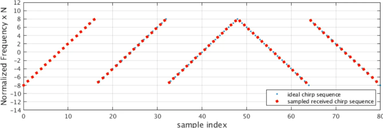
Finally, Figure 4 shows the impact of SF O on an otherwise perfectly synchronized signal. In the figure, we observe the effect of a receiver with a slightly higher sampling frequency to that of the emitter. We observe a cumulative sampling offset which has the effect of slowly moving the samples off of the desired integer frequency bins. If this offset is not corrected,
Fig. 3. Plot of N ∗ normalized frequency component of SN0(n) assuming N = 16 and N0= 0 and for a signal composed of three up-chirps and two
down-chirps. Top: signal received at the antenna suffering from an ST O of 7.2 samples and a CF O of 3.5 frequency bins. Bottom: same signal after sampling at a normalized rate of 1/N (assuming SF O = 0).
the demodulator will start confusing a symbol (identified by its frequency bin) with its next neighbor. This is an important problem for high order modulations. For example, the highest order modulation in LoRa has N = 4096. Assuming low cost quartz crystals with a ±20 ppm precision are used in both emitter and receiver, a potential worst case offset of 40 ppm can lead to a drift of 0.16 sample after a single symbol. While this effect can sometimes be ignored during preamble acquisition, for example if the preamble is relatively short, this effect must imperatively be corrected during the demodulation phase of frame detection. An estimation of SF O can be extracted from CF O if the source of both offsets, the quartz crystal reference, is identical.
D. Fundamental frame synchronization algorithm
As seen previously, in minimum sampling rate receivers, it is impossible to distinguish between ST O and CF O. Luckily, the presence of both up-chirps and down-chirps in a synchronization preamble leads to an elegant solution for extracting the integer part of both values. Neglecting noise, SF O and the fractional parts of both ST O and CF O, and assuming that the first part of the preamble is a base up-chirp, the received signal, r[k], can be written as follows:
r[k] = Aej2π(2Nk2+k(
(N −ST Oint)
N −
1
2))× ej2πkCF Oint/BW +jφo
where φo is the carrier phase offset and A is the signal
amplitude. Indeed, integer ST O has the same effect as symbol modulation. Multiplying by the conjugate of B[k] produces:
r[k] × B[k]∗= Aej2πk(CF OintBW +
(N −ST Oint)
N )× ejφo (2)
Thanks to a Fourier Transform applied on this signal and the extraction of argmax, we can extract the normalized frequency fup= CF Oint/BW +(N −ST Oint)/N . Now assume that in
a following moment of the preamble, a down-chirp, necessarily suffering from the same CFO and STO as the previous signal, is received: r[k] = Ae−j2π(2Nk2+k( (N −ST Oint) N − 1 2))× ej2πkCF Oint/BW +jφo Multiplying by B[k] produces: r[k] × B[k] = Aej2πk(CF OintBW −(N −ST Oint)N )× ejφo
Similarly, we extract the normalized frequency fdown =
CF Oint/BW − (N − ST Oint)/N . Thanks to these two
equations, the two unknowns, ST Oint and CF Oint, can be
estimated ( [ST Oint and \CF Oint). Of course, this assumes
that these calculations are applied in the moments when the receiver knows when to expect up and down chirps.
Interestingly, the above analysis can be used to extract the maximum CF O range that can be recovered by the receiver. Since fup and fdown are normalized frequencies, they are
defined modulo 1, i.e. any value v exceeding 1 will become v mod 1. Combining the two equations above, we find that CF Oint/BW = (fdown+ fup)/2. Since fdown+ fup is also
a modulo 1 normalized frequency, CF Oint/BW can only be
Fig. 4. Plot of N ∗ normalized frequency component of SN0(n) assuming N = 16 and N0= 0 and for a signal composed of three up-chirps and two
down-chirps. Signal after sampling at a normalized rate of 1/N but with a small SF O (assuming ST O and CF O = 0).
defined modulo BW/2. This means that the receiver will be able to recover a CF O limited to the range [−BW/4, BW/4]. For example, assuming BW = 125 kHz and a 868 MHz carrier, acceptable CF O must remain below 36 ppm. E. Extracting CF Of rac
As stated previously, the presence of a fractional CFO will cause a loss in sensitivity at low signal to noise ratios. Thus, compensating for CF Of racwill recenter the FFT outputs onto
integer frequency bins. The extraction of CF Of rac can be
achieved simply during the reception of two consecutive iden-tical symbols, e.g. two up-chirps or two down-chirps. Assum-ing that these two symbols are up-chirps, each of these sym-bols is processed as in (2) but this time the resulting frequency component is (CF Oint+CF Of rac)/BW +(N −ST Oint)/N .
Since this frequency is identical for both symbols, the same FFT bin, fup will be selected by the argmax function. The
signal present in the FFT bin corresponding to fup can be
expressed as:
ej2πkfup+j2πkCF OfracBW
This can be seen as a signal with constant frequency fupbut
with a time-varying phase. Therefore, if the phase, respectively φ1 and φ2, of the signal present in this FFT bin is extracted
for these two consecutive identical symbols, we can write: φ2− φ1=
CF Of rac
BW (k + N ) −
CF Of rac
BW (k) from which we find CF Of rac = BW (φ2− φ1)/N . This
technique is applicable as long as the two consecutive symbols are identical.
III. RELATED WORK
The reverse engineering efforts mentioned previously [3][4][5][6] employ wide-band software-defined radios (SDR) and over-sample captured frames emitted by LoRa-compatible RF transmitters. These samples can be stored in memory and post-processed by powerful CPU’s running potentially complex synchronization and demodulation algorithms. In
[3], a synchronization algorithm is proposed based on cross-correlations of the signal’s instantaneous frequency. Unfor-tunately, this algorithm is only effective at high signal-to-noise ratios, severely limiting the sensitivity of the receiver, and has a complexity O(N2). The patent in [18] proposes
an FFT-based demodulation algorithm for chirp modulated signals and, to the authors’ knowledge, is the first to mention the impact of CF Of rac on performance. The compensation
algorithm proposed is however much too complex for low cost, low power transceivers. The authors in [16] study optimal receiver algorithms, which have O(N log N ) complexity, for a minimum rate receiver. However, they do not resolve the time/frequency ambiguity discussed above leading to a limited capacity for CFO compensation. In addition, the algorithm proposed for CF Of rac estimation is less precise and
need-lessly complex compared to the one presented in Section II-E, as will be discussed in Section V-D. Finally, they do not address ST Of raccompensation. While publicly available, the
algorithms described in [19] for minimal rate, optimal LoRa synchronization are difficult to understand. Providing a clear explanation of these algorithms is the focus of the following section.
IV. LORA FRAME SYNCHRONIZATION
The techniques presented in II-D and II-E are the basic func-tions necessary to recover ST Oint, CF Oint and CF Of rac
which are imperative to accurately achieve frame synchro-nization in sub-zero SNR conditions. When and how a given receiver actually extracts this information from the received signal is implementation dependent. This section focuses on the acquisition of frames that follow the format defined in the LoRa physical layer.
A. LoRa frame format
In the FSCM modulation employed in LoRa, N is always a power of 2 since this eases FFT-based detection. For a given BW, an adaptive modulation is proposed allowing N to take on the value 2SF, with SF = {7, 8, 9, 10, 11, 12}. In the context of LoRa, SF is referred to as ‘spreading factor’.
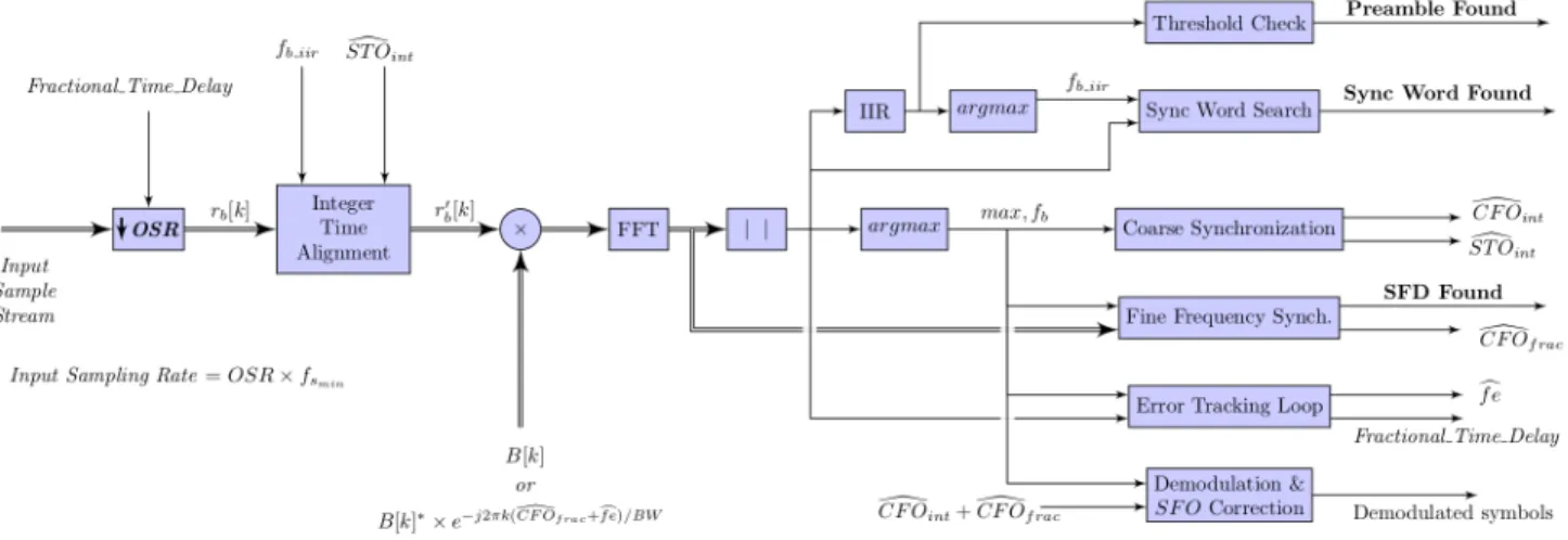
Fig. 5. Conceptual view of LoRa start-of-frame synchronization algorithm. Double arrows indicate complex signals.
Since we are interested in the synchronization phase of frame acquisition, referring back to Figure 1, we will fo-cus on the synchronization header including the ‘pream-ble’, ‘frame synchronization’ (also called sync word) and ‘frequency synchronization’ symbols of LoRa frames. The preamble consists of Npreambleun-modulated up-chirps, with
Npreamble ∈ {2, .., 65535}. Next, while [20] mentions that
the frame synchronization symbols consist of 2 symbols of value {x, N − x}, frame acquisitions made by [4] show that these symbols actually consist of two identical consecutive symbols {x, x}, the value of which is defined by the settings of the transceiver (note that they can be set to zero, making them identical to the preamble symbols). These symbols can be used to uniquely identify a network thus easing the filtering out of unwanted frames. Finally, the frequency synchronization symbols consist of 2.25 down-chirps symbols. Depending on the synchronization algorithm employed, the last quarter-symbol can be used by the receiver to apply the required time and frequency compensations before the start of data demodulation.
B. LoRa frame synchronization algorithm
The information present in [19] can be used to reconstruct the synchronization algorithm present in state of the art re-ceivers. A schematic overview of this algorithm is presented in Figure 5 in which the samples are processed from left to right while the different steps of the algorithm, corresponding to the different phases of frame synchronization, flow from top to bottom, with some processes occurring simultaneously as will be described below. While existing commercially available LoRa transceivers can be programmed to emit and receive frames containing only two preamble symbols1, measurements
show that in order to synchronize correctly, in practice the receiver needs a minimum of 4 preamble symbols (Figure 8). In addition, measurements show that if the received frame contains more preamble symbols than expected, the frame is rejected. Figure 6 shows an example as seen by the emitter
1Here we use the same terminology as in Figure 1.
(top) and by the receiver (middle and bottom) of a worse-case synchronization scenario, i.e. the emitted frame contains only two preamble symbols and therefore only a single block of received samples, r1[k], contains a complete preamble
symbol (for simplicity, N = 16). In this example, we choose frame synchronization symbols with modulation value of 2, meaning that the chirp’s initial frequency is offset by 2 integer frequency bins with respect to the base chirp. The signal as seen by the receiver will suffer from ST O and CF O thus resulting in a random circular frequency shift. In the example presented in Figure 6, a shift of +6 bins is applied to the signal in the top graph to obtain the signal in the middle and bottom graphs. The synchronization strategy illustrated in the middle graph is discussed in the following paragraph whereas the strategy illustrated in the bottom graph is discussed in section V-E.
1) Preamble synchronization: When the receiver is acti-vated, it starts receiving samples in successive non-overlapping windows (referred to as ‘blocks’) of size N , denoted rb[k],
with b the block index. These are processed as in (3) in order to extract consecutive FFT bin indices: {..., fb, fb+1, fb+2, ...}2:
fb = argmax(|F F T (rb[k] × B[k]∗)|) (3)
Since each block of samples is not synchronized with the emitted symbols, they necessarily contain samples that belong to chirp fragments of two different symbols. In high SNR conditions, the result of (3) will reflect the frequency offset due to the larger chirp fragment. For example, if we consider blocks r1[k] and r2[k] from the bottom graph of Figure 6, these
would produce f1 = 2 and f2 = 4. As discussed previously,
the frequency offset measured in r1[k] is the result of both
ST O and CF O which cannot be distinguished at this point. However, f1can be used to realign block r20[k] (middle graph
of Figure 6) on what is seen by the receiver as the start of a base chirp.
2The values of f
bcan be seen, as here, as FFT bin indices numbered from
1 to N , or alternatively, as normalized frequencies that take on the values k/N with k = 1..N .
Fig. 6. Plot of N ∗ normalized frequency component of the baseband signal, assuming N = 16. Top: synchronization header as seen by the transmitter and assuming frame synchronization symbols with modulation value of +2. Middle and bottom: the same signal as seen by the receiver after a shift of +6 bins (assuming SF O = 0 and CF Of rac= 0). The middle and bottom figures illustrate two different synchronization strategies.
In low SNR conditions, the use of a single preamble symbol can lead to a high error probability in the extraction of f1. Suppose now that the receiver is turned on earlier and
that the received signal contains several blocks (theoretically, up to 65535) which contain un-modulated preamble sym-bols. As discussed in [19], it is advantageous to average the FFT magnitudes of successive blocks before applying the argmax function. Indeed, since successive symbols are identical,3 this will average out the bins which contain only
noise, easing the extraction of the correct bin. Of course, this accumulation cannot be applied to blocks containing frame synchronization samples whose modulation value is not zero. In a low complexity implementation in which the amount of sample storage space is limited, an IIR filter such as y[n] = x[n] + αy[n − 1] can be used instead of averaging, with α < 1 representing the proportion of the previously received blocks that is ‘remembered’. The positive impact of this averaging operation can clearly be seen both in simulation and measurement on Figures 7 and 8. Figure 7 shows the simulated frame synchronization miss-detection probability versus the number of complete received preamble symbols whereas Figure 8 shows the measured sensitivity as a function of the number of transmitted un-modulated preamble symbols. As stated in [19], robustness can be further improved by imposing that the maximum FFT magnitude value which is selected by the argmax function exceed a threshold. This threshold can be designed to be proportional to the noise level present in the other frequency bins.
2) Frame (sync word) synchronization: Once a realignment by f1 has been applied, the search for the two frame
syn-chronization symbols (sync word) starts. Indeed, we expect
3This is true only if we ignore SF O which, for very long preambles,
will tend to progressively shift the bin value extracted from the accumulated magnitudes.
Fig. 7. Simulation (infinite precision) results showing the probability of sync worddetection failure versus the number of complete un-modulated preamble symbols received by the receiver. Here sync word value is +8, SF = 7, BW = 125 kHz, α = 0.5. ST Ointand CF O are chosen randomly between
[0, 1,.., 2SF − 1] and ±34 ppm, respectively. SF O and ST O
f racare set
to zero.
that blocks r02[k] and r30[k] will produce f20 = 2 and f30 = 2
since +2 is the modulation value corresponding to the frame synchronization symbols in our example (middle graph of Figure 6). Recall however that the presence of CF Of rac
and noise can easily cause ±1 bin errors (or more). Thus, rather than searching for a specific sequence of bin values over successive blocks, the frame synchronization algorithm proposed in [19] monitors the FFT absolute values in the desired and undesired frequency bins (±1) in two successive
4 5 6 7 8 9
Number of programmed preamble symbols
-130 -128 -126 -124 -122 -120 -118 Sensitivity (dBm)
Fig. 8. Sensitivity, defined as 5% PER for 66 byte packets, measured on SX1276 chip versus the number of TX and RX programmed preamble symbols, SF = 7, coding rate = 4/5, non-zero frame synchronization symbols, BW = 125 kHz, carrier frequency = 867.1 MHz.
blocks.
An effective frame filtering feature can be achieved simply by programming the receiver with the number of un-modulated preamble symbols it should expect before successfully de-tecting the frame synchronization symbols4. In this way, transmitted frames with longer preambles than expected can be automatically rejected.
3) Coarse time and frequency synchronization: Once frame synchronization is achieved, the next two blocks, r40[k] and r50[k] in our example, are used to find the frequency synchro-nization symbols. This is achieved as in (3) but this time with the un-conjugated base sequence B[k]. Since r50[k] contains only down-chirp samples, f50 is more reliable than f40 and is
probably used as fdown. Next, since fupis f1calculated above,
estimates of ST Ointand CF Oint( [ST Ointand \CF Oint) can
be calculated as discussed in II-D.
4) Fine frequency synchronization: As discussed in II-E, the phase of the FFT output in bin fdown of the two more
recently processed blocks (r04[k] and r05[k] in our example) is
used to estimate CF Of rac. Unfortunately, since it is calculated
using only two blocks, this estimation, \CF Of rac, will be
relatively imprecise, as shown in Figure 10, leaving a residual fractional frequency error that will be corrected by the tracking loop described below. As discussed in [16], \CF Of rac can
be compensated by multiplying the received signal, or the reference base chirp, by:
e−j2πk\CF Of rac/BW, k = 0, .., N − 1
5) Fine error tracking loop: At this point, we have success-fully estimated \CF Oint, [ST Oint and \CF Of rac. The
pres-ence of ST Of rac, which generates inter-symbol interference,
and a small residual fractional frequency error will have as consequence to spread the symbol energy onto more than one FFT bin. (Note that this is true even in steps 1 and 2 presented above.) For every block rb[k] processed according
to (3) and producing fb, the extent to which the symbol energy
is shifted to the next nearest FFT bins, which is indicative
4Measurements confirm that this feature is implemented on commercially
available hardware.
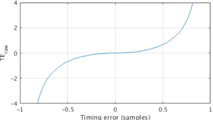
Fig. 9. Plot of T Erawversus the ‘timing error’. This curve is obtained
in simulation by oversampling a base chirp sequence, down-sampling with a fractional timing error, and comparing the FFT magnitudes in the adjacent bins versus the primary frequency bin.
of the fractional timing and frequency errors, is estimated in [19] by subtracting FFT magnitude of the next higher FFT bin (modulo N) from the FFT magnitude of the next lower FFT bin (modulo N) and dividing the result by the FFT magnitude in bin fb. This produces a “raw timing error”, T Eraw, that can
be converted to a fractional ‘timing error’ by inverting the conversion function plotted on Figure 9. The ‘timing error’ corresponds to a fraction of the sample duration 1/fsmin and
is an approximation of ST Of rac if the residual fractional
frequency error is ignored. Figure 9 is obtained in simulation by measuring the magnitude of the FFT output in adjacent versus desired bins when the received symbol is sampled with a fractional timing offset.
Recall however that this ‘timing error’ is produced by simultaneous fractional time and frequency offsets which cannot be distinguished. As explained in [19], thanks to the time/frequency equivalency of chirps, small time mis-alignments can be compensated by a proportionally small frequency offsets. Two compensation methods are therefore used simultaneously to correct this ‘timing error’: Part of this error can be compensated in the decimation chain of the receiver’s digital front-end (DFE). For example, suppose that a factor of 10 decimation is applied before the samples are produced at the minimum sampling rate fsmin. Fractional
timing offsets that are multiples of 1/10 can easily be created by shifting the decimation operator’s input by a corresponding number of undecimated samples. The remaining part of the ‘timing error’, te, can be converted to a frequency error byb applying the time to frequency conversion allowed by the time/frequency equivalency of chirps: cf e = (BW ×te)/N .b Frequency compensation can then be applied by applying a constant frequency offset to the base chirp used in (3) as follows:
B[k]0= B[k] × e−j2πkcf e/BW, k = 0, .., N − 1 (4) In [19], it is proposed that this error tracking loop can be activated starting from the very first block of samples received. The idea is that, since the effect of this compensation is to recenter symbol energy onto a single bin, the loop should ease the detection of the preamble and frame synchronization
sate for \CF Oint, \CF Of rac, [ST Oint and [ST Of rac. Data
demodulation can now start. Since ST Oint has been found
in step 3, it can be used to perform the correct alignment of the contents of the next processed block on the start of the data samples, illustrated by the block r700[k] in the middle
plot of Figure 6. Symbol demodulation can be achieved in the following manner: fsymbol= {argmax(|F F T (rb0[k] × B[k]∗× e−j2πk( \ CF Ofrac+ cf e BW )|) − \CF Oint× (N/BW )} mod N (5)
7) Sampling frequency error compensation: As discussed in II-C, even after compensating for both ST O and CF O, a sampling frequency error will gradually introduce an error in the samples contained in consecutive blocks, with the symbol energy associated with a complete chirp incrementally spreading to a duration greater or lesser than N × fsmin. If
the RF carrier and the sampling clock are generated from the same crystal-based reference clock, CF O and SF O are related by the expression SF O = fsmin × CF O/fc, where
fc is the RF carrier frequency. Thus, once CF O has been
estimated in steps 3 and 4 above, the corresponding SF O estimate, [SF O, can be calculated. Depending on the sign of [SF O, the received signal will suffer from an incremental delay (or advance) of SF Odelay= N × [SF O/fsmin samples
every block of N samples. The fractional part of this delay (or advance) can be compensated by the error tracking loop by summing SF Odelay and the timing error calculated in
step 5 above. The integer part of this delay (or advance) can be compensated by removing (or duplicating) a sample when necessary, as proposed in [16]. However, differently from [16], compensating the fractional timing error using the error tracking loop avoids having to over-sample the signal by a factor of 2, an approach which comes at a very high energy and complexity cost.
The compensation of the incremental delay (or advance) is necessary to avoid losing symbol synchronization while demodulating the data symbols. However, the presence of SF O means that the slope of the received chirp will be slightly different from the expected one. This will tend to shift the demodulated symbol energy away from a single frequency bin, hence lowering demodulation performance. In order to recenter the symbol energy, it is possible to adjust the frequency slope of the reference base chirp B[k] used in (5) to match the slope of the received chirps, as discussed in [19] and [16].
5This claim has not been verified in this present work.
aim of this section is to discuss the inherent computational complexity of the above algorithm and the adaptations that would be required in an ULP-SDR implementation.
A. Discussion on algorithm complexity
While the algorithm described in IV-B can appear relatively complex, we observe that, for each block, the basic algorithm consists in a multiplication of the block’s samples with some variant of the base sequence B[k], followed by an FFT of size N , followed by an absolute value calculation on the FFT outputs and, finally, the search for the argument of the resulting maximum. This is true in all phases of the algorithm (with small variants, e.g. IIR filtering during preamble detection). Computational complexity therefore essentially consists of N sine and cosine calculations to adjust the angle of the base sequence B[k] with respect to cf e, \CF Of rac, and SF O,
followed by N complex multiplications, a complex FFT of size N , and N magnitude calculations.
B. Algorithm variants in the ULP-SDR context
Part of the difficulty in the synchronization algorithm presented above is due to the fact that sampling at fsmin
makes it more difficult to distinguish timing and frequency errors due to the folding over of the frequency signal. In an SDR context, since oversampling avoids this effect, at first thought, oversampling might be considered a good approach for lowering the complexity of the synchronization algorithm. However, higher sampling rates necessarily increase the re-quired digital baseband (DBB) processing clocks, potentially leading to greater energy expenditure.
The main difficulty in implementing the above algorithm in an ULP-SDR context lies in realizing the error tracking loop feedback signal that adjusts the delay at the input of the deci-mation block in the receiver’s digital front-end. Implementing a decimation block in software would imply a large power burden. Alternative approaches for compensating ST Of rac
include adding a linear interpolation block at the input of the baseband receiver6 or by using a compensation approach
as in (4) but this time with a frequency error coefficient corresponding to the complete ‘timing error’. The analysis of these approaches is left to future work.
In the following sections, we propose several ideas that might be exploited by the research community to improve or create variants of the above algorithm, especially in the context of low complexity receivers.
6A first order interpolation would require two multiplications, one sum and
C. If Npreamble > 2: Alternative preamble synchronization
algorithm
The preamble synchronization algorithm proposed in step 1 (section IV-B) is designed to capture frames in which the preamble is as short as possible, the worst case being a single complete preamble symbol. In favorable SNR condi-tions, the ability to achieve very quick synchronization lowers frame transmission and reception energy overheads and link latency. In less favorable conditions as shown in Figure 7, the probability of error in the value of fb obtained using (3)
without the noise reduction effect of the IIR filter can be important, potentially leading to many dropped frames due to the incorrect frame synchronization detection in step 2.
Using a larger number of preamble symbols improves performance in low SNR conditions thanks to the IIR filter discussed above. In this context, another approach that could be used to improve the preamble synchronization phase, espe-cially in the absence of an error tracking feedback loop, con-sists in using a pattern matching algorithm on the successive outputs of (3): {f1, f2, f3, ...}. Detecting that these values have
stabilized around a single value (or two adjacent bin values since fractional time and frequency errors can lead to FFT outputs that fall between two bins) can be an alternative mean for detecting the presence of a preamble with high certainty.
D. If Npreamble> 2: Alternative fine frequency
synchroniza-tion algorithm
Again in a context where expected frames contain more than two preamble symbols, we observe that the estimation of \CF Of rac, previously performed in step 4 using blocks
containing the two down-chirps, can now be operated in the preamble synchronization phase of the algorithm since identical symbols are being received. This has the advantage of producing a higher precision estimate of CF Of rac since the
successive estimates can be averaged, reducing the impact of noise. In addition, applying an early \CF Of raccorrection will
improve both the frame and coarse synchronization phases. To study the impact of \CF Of rac estimation precision
in various Eb/N o conditions, infinite precision Monte-Carlo simulations are run in which frame synchronization is per-formed assuming frames affected by a CF O randomly chosen in the range of ±34 ppm. CF Of racestimation is performed on
the preamble symbols using the method described in Section II-E. For comparison, Figure 10 also shows the accuracy of the CF Of rac estimation method proposed in [16], equation
(9). We see that, not only does this last algorithm perform less accurately at low Eb/N o, the algorithm itself requires 2SF additional complex multiplications and sums per symbol
employed.
Finally, we observe that it is also possible to estimate CF Of racusing the blocks containing the two frame
synchro-nization symbols, assuming the two symbols are identical. This estimate could be averaged with the one extracted from the two down-chirpsymbols.
Fig. 10. Standard deviation of the CF Of racestimation error versus the
number of symbols over which the estimation is averaged (BW = 125 kHz, SF = 7)
E. Alternative frame (sync word) synchronization algorithm In an alternative approach to the frame synchronization algorithm presented in step 2 of section IV-B, rather than searching for the frame synchronization symbols after real-izing a time realignment by f1, the search for these symbols
can be done using the next, un-realigned blocks (r2[k] and
r3[k] in the bottom plot of Figure 6). Assuming that the
frame synchronization symbols employ a modulation value of 2, initial frame synchronization will be achieved if the receiver finds the sequence {..., f1, f1+2, f1+2, ...}. However,
since at this point ST Of rac (and potentially also CF Of rac)
errors remain and thus FFT outputs can fall between two bins, the pattern matching algorithm should accept ±1 bin errors on the extracted bin indices. Alternatively, the output of this bin pattern matching search could also be combined with the output of the magnitude pattern matching search of the original algorithm.
F. An algorithm for resolving data start block ambiguity Among the FSCM frame synchronization requirements stated in section II-C, we mentioned the existence of an ambiguity concerning the header or payload start time. This ambiguity stems from the fact that the samples corresponding to the two and a quarter down-chirps can be spread over 3 or 4 blocks (for example, in the middle plot of Figure 6, they are contained in blocks r40[k], r05[k] and r06[k]). This means that,
even once coarse time synchronization has been performed in step 3 and thus [ST Oint has been calculated, there remains
some uncertainty as to the block index which contains the very first data (header or payload if there is no header) symbol sample. Resolving this uncertainty is necessary for correctly
blocks and down-chirps then makes it easy to identify the two complete down-chirps contained in the frame using the FFT magnitude. This is the approach used to obtain the ideal synchronization result shown in Figure 11. However, in a low complexity receiver, these additional computations and additional memory requirements should be avoided.
Here, we present a low complexity technique for resolving this ambiguity: Once steps 1, 2, 3 and 4 have been performed, since [ST Ointand fdownare known, it is easy to calculate the
expected number of down-chirp samples that will be contained in the M successive blocks suspected of containing down-chirp samples. (For example, M can be set to 5.) These values are stored in the expected samples vector7. Assuming
the FFT magnitudes for these M blocks have been stored in memory, a second vector named measured magnitudes is constructed by extracting the FFT magnitude outputs at the index fdown for these M blocks. At high SNR, we indeed
expect that this vector reflect the proportion of down-chirp samples contained in each block. Finally, if we apply a con-volution of expected samples with measured magnitudes, the maximum of the convolution result can be used to identify the block index containing the start of the data symbols. For greater clarity, a pseudocode version of this algorithm is described in Algorithm 1.
Algorithm 1 Data start block ambiguity resolution algorithm Perform step 1
/* Now assume P reamble F ound = T RU E */ for ( i = 0 ; i < M ; i++ ) do
For each block i, compute (3)
For each block i, store the N computed FFT magnitudes in memory
if Sync W ord F ound == FALSE then Perform step 2
else
/* Sync word has been found */ Perform steps 3 and 4
end if end for
/* [ST Oint and fdown are now known */
Using [ST Oint, computeexpected samples vector
Using fdown and stored FFT magnitudes, compute
measured magnitudes vector
Convolveexpected samples with measured magnitudes Data Start Block = index of maximum value of convolution vector
Perform steps 5, 6 and 7
7Precisely, expected samples = [.., 0, N − [ST O
int, N, 1.25 × N −
(N − [ST Oint), A, 0, ..], where A = 0.25 × N − (N − [ST Oint) if
A > 0 or 0 otherwise. For example, if N =128, M =6 and [ST Oint = 0,
expected samples = [0, 0, 128, 128, 32, 0].
for outlier detection [21]: for a given dataset, outliers are detected by dividing the gap between each value and the values’ expected range. In our case, we define the range as the absolute value of the difference between the first two values of the measured magnitudes vector: range = |measured magnitudes[2] − measured magnitudes[1]|.
Indeed, since down-chirps are not present, we expect these values to contain only noise. For each other element of the measured magnitudes[i] vector (i = 3, .., M ), a new value is calculated (and stored in a vector called Dixon magnitudes) by dividing the distance (gap) be-tween the value and the largest of the first two values by range. In a noisy context, this means that blocks containing down-chirp samples will be identified as outliers. Finally, the expected samples vector can be convolved with the Dixon magnitudes vector to identify the block containing the start of the data samples.
In Figure 11, we present simulation results of frame syn-chronization failure, meaning that the algorithm was unable to identify the first data sample hence leading to complete frame loss, for different synchronization algorithms. Simulations are run in the following conditions: BW =125 kHz, SF = 7, frames contain 6 preamble symbols and the two frame syn-chronization symbols (sync word) are set to 0. CF O is chosen randomly in the range ±34 ppm, ST Oint is chosen randomly
in the range [0, 127], SF O and ST Of rac are set to 0. The
proposed low complexity algorithm employs the alternative techniques described in Sections V-C and V-D as well as the technique based on Dixon’s test presented above (M =6). We compare the performance of this algorithm with the ideal, high complexity, synchronization algorithm discussed above and with another low complexity algorithm based on a simple heuristic rule for choosing the block containing the first data sample: the two largest values of the measured magnitudes vector, presumably corresponding to blocks containing the largest number of down-chirp samples, are compared. If these values increase with block index, the block index following that of the greater value is assumed to contain the first data sample. If these values decrease with block index, the block index of the smaller value is assumed to contain the first data sample. As can be seen, such a simple rule leads to very poor results.
The good performance of our proposed low complexity algorithm lies in the fact that, if fup and fdown are extracted
with high certainty (which is the case when the frame contains more than two preamble symbols), then so is [ST Ointand so is
the expected samples vector. Since the convolution with the Dixon magnitudes vector gathers information from several blocks, this leads to very high synchronization accuracy even in very low SNR conditions. The computing cost of this technique is very low and is essentially due to the memory that is required to store FFT magnitude outputs for the M
Fig. 11. Simulation results of frame synchronization failure (BW = 125 kHz, SF = 7)
blocks.
VI. CONCLUSION
The importance of the LoRa physical layer for the IoT community prompted our efforts to provide a clear explanation of the timing and frequency synchronization requirements necessary for the detection of LoRa-modulated frames. For the first time, a method for resolving integer symbol timing and carrier frequency offset ambiguity, resulting from the use of minimum sampling rate receivers, is described. In particular, we show how robust frame detection can be performed while constantly focusing on low complexity implementations of the proposed algorithms. Our aim has been to propose a large number of algorithm variants in order to spur creativity in the design of new FSCM-based physical layer protocols and detection algorithms, especially in view of ultra-low power, software-defined radio implementations. Indeed, it is the authors’ firm belief that, thanks to minimal complexity algorithms, software-based FSCM transceivers will soon offer competitive power consumption figures compared to tradi-tional hardware implementations.
Finally, we also provide simulation and measurement re-sults showing the relationship between number of received preamble symbols and both frame detection performance and fractional CFO estimation error. These results should be of particular value to low power protocol designers whose con-stant concern is finding the perfect balance between protocol overheads, transceiver power consumption and link reliability.
ACKNOWLEDGMENT
The authors would like to thank Reda Bekkar of CEA, Sylvie Charbonnier and Chhayarith Heng-Uy of Gipsa-Lab and Mathieu Xhonneux of UCLouvain for fruitful discussions.
REFERENCES
[1] I. Markit. (2018) Connectivity technologies, an in-depth view into the competition, applications and influencers driving the foundation of IoT. [Apr. 11, 2019]. [Online]. Available: https://ihsmarkit.com
[2] J. Haxhibeqiri, E. De Poorter, I. Moerman, and J. Hoebeke, “A survey of LoRaWAN for IoT: From Technology to Application,” Sensors, vol. 18, no. 11, 2018. [Online]. Available: http://www.mdpi.com/1424-8220/18/11/3995
[3] P. Robyns, P. Quax, W. Lamotte, and W. Thenaers, “A Multi-Channel Software Decoder for the LoRa Modulation Scheme,” in 3rd Interna-tional Conference on Internet of Things, Big Data and Security, Jan. 2018, pp. 41–51.
[4] B. Sikken. Decoding Lora. [Apr. 9, 2019]. [Online]. Available: https://revspace.nl/DecodingLora
[5] M. Knight, “Reversing LoRa: Exploring Next-Generation Wireless.” in GRCon, 2016.
[6] J. Blum. (2016) LoRa modem with LimeSDR. [Apr. 11, 2019]. [Online]. Available: https://myriadrf.org/news/lora-modem-limesdr/ [7] S. Wu, S. Kang, C. Chakrabarti, and H. Lee, “Low power baseband
processor for IoT terminals with long range wireless communications,” in 2016 IEEE Global Conference on Signal and Information Processing (GlobalSIP), Dec 2016, pp. 728–732.
[8] Y. Chen, S. Lu, H. Kim, D. Blaauw, R. G. Dreslinski, and T. Mudge, “A low power software-defined-radio baseband processor for the Internet of Things,” in 2016 IEEE International Symposium on High Performance Computer Architecture (HPCA), March 2016, pp. 40–51.
[9] H. Belhadj Amor and C. Bernier, “Software-hardware co-design of multi-standard digital baseband processor for IoT,” in 2019 Design, Automation Test in Europe Conference & Exhibition (DATE), March 2019.
[10] C. Heng Uy, C. Bernier, and S. Charbonnier, “Energy Efficient Channel State Classification for Lifetime Enhancement of LPWA Networks,” in 11th International Conference on COMmunication Systems & NET-workS, Bangaluru, India, Jan. 2019.
[11] ——, “Design of a Low Complexity Interference Detector for LPWA Networks,” in IEEE I2MTC 2019. IEEE International Instrumentation
and Measurement Technology Conference, Auckland, Australia, May 2019.
[12] L. Vangelista, “Frequency shift chirp modulation: The LoRa modula-tion,” IEEE Signal Processing Letters, vol. 24, no. 12, pp. 1818–1821, Dec 2017.
[13] C. Gupta, T. Mumtaz, M. Zaman, and A. Papandreou-Suppappola, “Wideband chirp modulation for FH-CDMA wireless systems: coherent and non-coherent receiver structures,” in IEEE International Conference on Communications, 2003. ICC ’03., vol. 4, May 2003, pp. 2455–2459 vol.4.
[14] K. Huang, Z. Wang, and R. Tao, “Study of incoherent demodulation technique in chirp spread spectrum communication systems,” in 2008 9th International Conference on Signal Processing, Oct 2008, pp. 1926– 1929.
[15] B. M. Popovic, “Generalized chirp-like polyphase sequences with opti-mum correlation properties,” IEEE Transactions on Information Theory, vol. 38, no. 4, pp. 1406–1409, July 1992.
[16] R. Ghanaatian, O. Afisiadis, M. Cotting, and A. Burg, “LoRa digital receiver analysis and implementation,” in 2019 IEEE International Conference on Acoustics, Speech and Signal Processing, May 2019, pp. 1498–1502.
[17] J. G. Proakis, Digital Communications. McGraw-Hill, 1995. [18] H. Tanaka, “A frequency and timing synchronization circuit making use
of a chirp signal,” Japanese Patent 12 969 998, April 24, 1998. [19] O. Seller and N. Sornin, “Low complexity, low power and long range
radio receiver,” European Patent 3 264 622, July 1, 2016.
[20] ——, “Low power long range transmitter,” European Patent 2 763 321, Feb. 5, 2013.
[21] W. J. Dixon, “Analysis of extreme values,” Ann. Math. Statist., vol. 21, no. 4, pp. 488–506, 12 1950. [Online]. Available: https://doi.org/10.1214/aoms/1177729747
Science and Engineering in Computer Engineering from the University of Toronto in 1998 and a PhD degree in Microelectronics from the National Poly-technical Institute of Grenoble in 2003.
Franc¸ois Dehmas received the Engineering diploma from SUPELEC, Gif-sur-Yvette, France. In 2001, he joined CEA-LETI, Grenoble, France, to work on 13.56-MHz RFID development and specifically the data rate improvement of such systems. Then, he focused on digital baseband algorithm design for low-power transceivers such as ZigBee and Bluetooth-LE. Since 2009, he has been working on the physical layer for UWB receivers and on algorithms for localization systems. Since 2012, he has also been working on LPWA protocols, studying new dedicated physical layers while participating in the development of digital baseband processors for CEA-LETI’s wireless transceivers. compliant to the Sigfox network or for Satellite IoT.
Nicolas Deparis received his Ph.D. Degree in mi-croelectronics in 2007 from the University of Lille, France. After his Ph.D. thesis on the transmission of Impulse Radio Ultra Wide Band (IR-UWB) signals in millimetre-wave (mmw) band, he joined the CEA-LETI Laboratory, Grenoble, France. He developed new electrical architectures for IR-UWB transceiver and mmw circuit design for ultra-low-power wireless communication using CMOS SOI advanced tech-nologies. He has also been involved in sub-GHZ IR-UWB project for localisation. In 2009, he joined Petzl, a French company as a radio engineer and project manager, where he developed a proprietary long-range audio full duplex communication system using LoRa signals at 2.4 GHz. He joined Idosens, a French industrial Internet of Things (IoT) startup company, in 2016. He developed a proprietary LoRa 2.4 GHz protocol and IoT architecture to enable low power wide area network (LPWAN) communication and indoor localisation based on two way ranging (TWR) time of flight (TOF) measurement. Since 2018, he has been working for the CEA-LETI at the Wireless Communication Department as a research engineer where he contributes and leads LPWAN projects on LoRa and UWB based systems.