Designing a Microhydraulically-driven Mini-robotic Squid
byKevin Dehan Meng
B.S., U.S. Air Force Academy (2014)
Submitted to the Department of Mechanical Engineering in partial fulfillment of the requirements for the degree of
Master of Science in Mechanical Engineering at the
MASSACHUSETTS INSTITUTE OF TECHNOLOGY June 2016
C 2016 Massachusetts Institute of Technology. All rights reserved.
Signature redacted
A uth o r...
Department of Mechanical Engineering May 20, 2016
Certified by...
Signature redacted
1'
Certified by: ...
.. ...
Jakub Kedzierski MIT Lincoln Laboratory
Signature redacted
10V 01
... ... ... ... Sang-Gook Kim Professor of Mechanical Engineering Thesis Supervisor
Accetedby:Signature
redacted
Accepted by: ...
u- e _re ac e
...
Rohan Abeyaratne
Chairman, Department Committee on Graduate Students
MASSACHUSETTS INSTITUTE OF TECHNOLOGY_
JUN 0
2
2016
LIBRARIES
MITtibraries
77 Massachusetts Avenue
Cambridge, MA 02139 http://Iibraries.mit.edu/ask
DISCLAIMER NOTICE
Due to the condition of the original material, there are unavoidable flaws in this reproduction. We have made every effort possible to
provide you with the best copy available. Thank you.
The images contained in this document are of the best quality available.
Designing a Microhydraulically-driven Mini-robotic Squid
byKevin Dehan Meng
Submitted to the Department of Mechanical Engineering on May 20, 2016 in partial fulfillment of the requirements for the degree of
Master of Science in Mechanical Engineering
ABSTRACT
The realization of a standalone microrobotic platform has thus far been elusive due to size, weight, and power constraints. Recently, a novel microhydraulic electrowetting actuator (MEA) has been developed at MIT Lincoln Laboratory, enabling powerful, efficient, and scalable actuation. The MEA's use of efficient (17 > 65%), low-voltage electrowetting (<25 V) and high power density favorably positions the actuator for applications in microrobotics, which includes systems on the centimeter-scale and below.
In this thesis, I present the design of a miniature robotic "squid" which features the MEA as the driving component. The system was inspired by cephalopod paralarvae, which
predominantly rely on jet propulsion in their early stages of development. The squid robot can produce thrust by diaphragm pump-like operation, in either single-acting or double-acting modes. Since the actuator is a critical component, further modeling and analysis on the MEA is first presented and confirmed by experiments. After demonstrating actuator reliability, the design and fabrication of the squid are presented, from component-level considerations to system
assembly procedures. High-resolution 3D printing methods are exploited to fabricate monolithic, multi-material structures and to develop passive flap check valves for gauging the pumping capability of MEA. The pump characteristics are modeled and tested, achieving flow rates of up to 1.79 mL/min. A finalized robotic squid design is predicted to swim at a velocity of 3 cm/s, which is comparable to that of young squid.
Suggestions are made for the continued development of the mini-robotic squid. It is hoped that the squid design presented herein will serve as a precursor to more advanced, standalone microrobotic systems, which may find use in medicine and defense-related applications.
Thesis Supervisor: Sang-Gook Kim
Acknowledgements
Many thanks are owed to the people who have supported me throughout my journey at MIT. Without a doubt, my master's thesis and research would not have been possible without their help.
I have had an amazing opportunity to learn at MIT under the guidance of a wise advisor. Professor Kim has been overly generous in providing insightful guidance and big-picture lessons that I will certainly draw upon in the future. My lab mates Jeff, Katie, Ray, and Yu have been very helpful in discussing various topics and easing my transition to graduate school.
I have received tremendous support from MIT Lincoln Laboratory, where I have conducted the bulk of my research. My research advisor Jakub Kedzierski has been very
influential in introducing me to MEMS research and modeling patience and innovation. I would like to thank my group leader, Mordechai Rothschild, and microfluidics group members, Shaun Berry, Todd Thorsen, Rafmag Cabrera, and Zach Weaver for sharing their enthusiastic support, technical knowledge, and time. At the TOIL and Packaging labs, I truly appreciate Dave Scott, John, and Mike Augeri for their willingness to help enable my efforts.
Outside of the laboratory, I have received much encouragement. I am always thankful for my family at home, as well as the family I've found through the campus Christian fellowship. Finally, I am grateful to God for bringing these wonderful friends and supporters into my life and for providing me wisdom and strength whenever I lacked.
Contents
Chapter I Introduction ... 13
1.1 Thesis Objective and Contribution ... 14
1.2 Organization ... 14
Chapter 2 Background ... 16
2.1 M icrorobotics ... 16
2.2 Actuation Technologies ... 17
2.3 Electrowetting ... 19
Chapter 3 M icrohydraulic Electrow etting Actuators ... 22
3.1 Operation Concept ... 22 3. 1.1 Capillary Pressure ... 22 3.1.2 Electrolytic Capacitors ... 23 3.1.3 Actuation Cycle ... 23 3.2 Fabrication ... .)6 3.3 M odeling ... 29 3.3.1 Scaling ... 30 3.3.2 Dynam ic Response ... 33 3.3.3 Optim ization ... 36 3.4 Experim ental ... 37 3.5 Reliability ... 40
Chapter 4 Squid Design ... 42
4.1 Inspiration ... 42
4.2 Propulsion Schem e ... 43
4.3 Actuator Configuration ... 44
4.6 Electrical W aveform ... 51 4.7 M odeling ... 53 4.8 M antle ... 55 4.9 Gasket ... 58 4.10 Electrode Plate ... 59 4.11 Sealing ... 64 4.12 Buoy ... 64 4.13 Interconnects ... 65 4.14 Check Valve ... 66
Chapter 5 Fabrication, Testing and Discussion ... 71
5.1 Fabrication ... 71 5.2 Valve Testing ... 75 5.3 Assem bly ... 82 5.4 Discussion ... 85 Chapter 6 Conclusions ... 87 6.1 Summ ary ... 87 6.2 Future W ork ... 88 Bibliography ... 90
List of Figures
Figure 1. Actuation Cycle [1]... 25
Figure 2. Coated Actuator, 25 ptm D ... 28
Figure 3. Capillary Curve for 25 jtm D actuator ... 29
Figure 4. Power Density Scaling Trend [1] ... 33
Figure 5. Lam bert W function [15]... 36
Figure 6. Experim ental Setup ... 38
Figure 7. Reliability Testing ... 40
Figure 8. Single-Acting Arrangem ent... 45
Figure 9. Double-Acting Squid Robot (back)... 47
Figure 10. Double-Acting Squid Robot (side)... 48
Figure 11. Actuator, 25 um D (backside) ... 50
Figure 12. Quadrature W aveform s ... 52
Figure 13. M antle Design (m ultiple views)... 57
Figure 14. Electrode plate with O-ring ... 60
Figure 15. Squid Electrical Circuit ... 61
Figure 16. Cantilever-type valve operation [21]... 67
Figure 17. 013 O-ring Gasket, glossy side (left) and m atte side (right) ... 73
Figure 18. Valve test piece, 3x2x0.75 m m 3 cantilever ... 74
Figure 19. Flap valve perform ance ... 75
Figure 20. Expanded flap valve perform ance ... 77
Figure 21. Sm aller flap perform ance ... 78
Figure 22. Pum p test assembly design... 80
Figure 23. Pum ping using designed flap valves ... 81
Figure 24. After step 4 ... 84
Figure 25. After step 7 ... 84
List of Tables
Table 1. Major actuator characteristics [9] [10] [11] [12]... 18
Table 2. MEA Fabrication Process ... 26
Table 3. Cytop Dip-Coating Process ... 27
Table 4. Parts of Test Setup ... 39
Table 5. Actuator Specifications... 49
Chapter
1
Introduction
Recent work at MIT Lincoln Laboratory has led to the development of a novel microhydraulic actuator that uses electrowetting as its actuation principle [1]. This
microhydraulic electrowetting actuator, or MEA, is able to "deliver high power at a relatively low voltage with an energy conversion efficiency of over 65%". A highlighted application of the MEA is microrobotics, toward which actuation of a PDMS soft robotic hinge is demonstrated as well as energy harvesting. In soft robotics, a pneumatic or hydraulic displacement is used to interface with solid objects by expanding and deforming inflatable components. However, actuators that produce a hydraulic displacement need not be limited to soft robotics applications. Instead of coupling a hydraulic displacement to a deformable bladder, the displacement can be directed ejected into an ambient liquid environment.
Taking inspiration from nature's squid, a microrobotic platform is designed to use microhydraulically-driven jet propulsion. Several jet-based underwater actuators have already been studied, such as vortex ring thrusters [2] and synthetic jet actuators [3]. While they may be viable options for larger-scale systems, their power requirements prohibit integration into robotic
systems on the size of 1 cm and below. Given the MEA's advantages and natural suitability for liquid environments, it offers unique potential to enable smaller, lighter, and more efficient microrobotic systems.
1.1 Thesis Objective and Contribution
A bioinspired design for a microhydraulically-driven mini-robotic squid has been devised. The design is meant to provide the framework for smaller, more efficient microrobotic platforms by featuring the microhydraulic electrowetting actuator as the driving component, with the goal of eventually enabling highly maneuverable devices in terms of weight and power requirements.
A double-acting diaphragm pump configuration is adopted as the squid architecture. The various parts of the squid design are presented, from component-level analyses to system-level
integration and testing. As a critical component, the MEA is studied further to verify its viability as a reliable actuation mechanism. A transient hydrodynamic model is used to predict actuation performance and thrust produced by the squid. For flow directionality control, flap-type passive check valves are designed and developed. Analysis and testing is performed on these valves before integration into the squid system.
Throughout the design process, the components were created with special consideration given to fabrication simplicity and interfacing. Lessons and common difficulties from novel fabrication techniques are shared. 3D-printing was selected to produce multi-material parts with complex geometries. Thus, 3D-printing is shown to be a practical method for rapidly prototyping components that can be interfaced with microfabricated actuators. As additive manufacturing technologies progress, it is expected that 3D-printing will become more widely accepted in microrobotics.
1.2 Organization
testing. Chapter 2 provides background on the diverse field of microrobotics, with a specific focus on efficiency and power density limitations. From actuation performance trends, a case is made for the application of microhydraulic actuators to microrobotics. Since the MEA employs a relatively new actuation principle, Chapter 3 thoroughly discusses the concept of operation, scaling model, and further testing to verify reliability. Chapters 4 and 5 report the final design, fabrication, and discussion of the squid system and testing directions. Finally, Chapter 6 briefly
summarizes the work and suggests future directions to enhance the performance of the microrobotic squid.
Chapter 2
Background
2.1 Microrobotics
Microrobotics, also known as microbotics, refers to the field of study concerned with miniature robotic systems and subsystems, with a loosely defined size scale ranging from
centimeters to microns. While the larger end of robots are built by hand, most of the smaller ones at the micron scale and below incorporate microfabrication processes.
Advances in microactuation technologies and fabrication methods, coupled with a
strategic demand for lower SWaP (Size, Weight, and Power), has fueled interest in microrobotics from various stakeholders. Envisioned applications for microrobots include remote monitoring, surveillance, search and rescue, nanoassembly, medicine, and in-vivo surgery. Robotics
platforms come as diverse as their possible applications, but most share a common factor: they are inspired by examples found in nature. This theme of bioinspiration is manifested in physical appearance, locomotion concepts, and swarm functionality.
The state of the art in microrobotics is arguably the RoboBee developed at Harvard, which uses flapping wings driven by piezoelectric bimorph actuators. Other significant advances include the Kilobot [4], and several novel concepts for untethered biomedical microrobots [5]. The Kilobot is powered by a coin-shaped inductive vibration motor, which produces a high frequency stick-slip motion for incremental movement. The CoCoRo project has developed intelligent aquatic swarm robotic systems for centimeter-scale, propeller-driven maneuvering [6].
Despite impressive efforts to mimic nature, the actuators driving these microrobotic systems are not as versatile as biological muscle, and come with unavoidable compromises.
While the aforementioned systems have offered valuable contributions to the field of microrobotics, they are accompanied by severe range limitations. Actuators needing high
operating voltages must be tethered to a power supply, although research is being done on lightweight power electronics circuits [7]. Many biomedical microrobot concepts are activated under the influence of a local magnetic field, and Kilobots rely on inductive vibration motors which can be inefficient. Although limited range may not be prohibitive for some applications, a much wider functionality set could be opened up for small-scale autonomous systems that have the ability to operate remotely. In many cases, limited range is inherent in a robot's actuation mechanism. Therefore, not only are increased efficiency and reliability crucial for progress, but power density is also a key parameter [8]. Therefore, an ideal actuator for microrobotics would be efficient, robust, and have a high power-to-volume ratio.
2.2
Actuation Technologies
At the microscale and beyond, many effects originally deemed negligible at the macroscale begin to dominate, enabling a diverse set of microactuation principles. Each
actuation technology possesses its unique advantages, thereby giving each a niche application. For autonomous robotic systems designed to be remotely operated, the key performance metrics are efficiency, power density, and reliability. Efficiency reduces the energy consumption and increases range, and power density is critical for low size and weight constraints. An often unreported metric is reliability, or the ability to actuate repeatedly for long periods of time or for many actuation cycles without failure, which is essential to consistent remote operation. For
centimeter-scale locomotion, the actuator must also be able to produce high force and displacement.
The general force-displacement, power density, and efficiency characteristics of major microactuator technologies are presented in Table 1.
Table 1. Major actuator characteristics [9] [10] [11] [12]
Type Force Displacement Power Density Efficiency
Shape memory alloy High High High Low
Piezoelectric High Low High High
Dielectric elastomer Medium High High High
Thermo-pneumatic High Medium Low Low
Electromagnetic High High Low Low
Microhydraulic [13] Medium High High High
From the list of major actuators, the electrostatic class of actuators was shown to be highly efficient. This category includes dielectric elastomers, piezoelectrics, and microhydraulic actuators. Performance specifications for dielectric elastomers are promising, but they are known to fail frequently from hysteresis and electrical shorting. Piezoelectric actuators produce high forces but with relatively low displacements. However, displacement can easily be amplified by adding leverage to the piezoelectric film. Microhydraulic actuators have similar advantages as piezoelectrics, but they operate at lower frequencies and lower voltages. Since electrostatically-controlled microhydraulic actuators produce a volumetric displacement, the theoretical force-displacement characteristics are gathered by normalizing to the actuator area. Among the MEMS
actuators that are viable, electrostatic actuation augmented by hydraulic amplification seems well-positioned for microrobotics applications.
An overview of major microactuation technologies reveals that microhydraulic actuators are uniquely positioned for aquatic microrobotics applications. The comparative advantages of microhydraulic actuators indicate potential to not only further advance the diversity of
microrobotics, but eventually enable untethered field-testable prototypes.
2.3 Electrowetting
The Bond number is a dimensionless parameter that gives the relative importance of gravitational forces to surface tension forces.
Bo - pgD 2
a
with density p, gravitational acceleration g, meniscus diameter D, and surface tension a. When Bo « 1, the effect of gravity can be neglected.
At Bo « 1, a small liquid droplet on a surface assumes a rounded profile governed by the surface energies of the material interfaces. The contact angle between the liquid, solid, and gas phases are consistently observed given the materials and conditions. The droplet contact angle is the result of a balance between cohesive forces within the droplet and adhesive forces at the solid-liquid interface, and can be consistently observed in controlled conditions. In static equilibrium, the contact angle of a droplet on a substrate can be predicted by a force balance applied at the three-phase contact line, known as Young's equation:
where 6
SL is the contact angle formed by the droplet on the substrate and yij represents the surface energies of the different interfaces formed by the liquid (L), vapor (V), and solid (S) phases. It is possible for another liquid can be substituted for the vapor phase.
In electrowetting, an electric field is applied to modify the surface energy and contact angle of various liquids. The addition of an applied voltage between the liquid and solid decreases YSL, and consequently decreases the solid-liquid contact angle. The surface energy between liquid and solid phases is altered due to build-up of an electric double-layer that enhances attraction. Common uses for electrowetting include droplet manipulation, micro-pumping, and bio-analysis. First experimented upon by Gabriel Lippmann in 1875,
electrowetting has been improved with significant advancements within the past few decades. While initial experiments yielded small contact angle changes due to electrolysis at low voltages, Bruno Berge later pioneered what is now called electrowetting-on-dielectric (EWOD), where a dielectric is inserted between the conductive solid and liquid phases allowing much higher voltages to be applied, leading to greater contact angle changes. Mugele presents a
comprehensive overview of electrowetting in [14].
Electrowetting is described by the modified Young's equation:
YSL = YSL 2
Ca =
t
Where YSL is the original solid-liquid surface energy, Ca the areal capacitance with permittivity of free space E0, dielectric constant E, and dielectric thickness t. The CV2 2 term represents the
Increasing the voltage will progressively decrease the contact angle regardless of voltage polarity. This continues until the point of contact angle saturation, at roughly OSL ~ 500, where
increasing the voltage no longer lowers the contact angle. The exact point of saturation depends on material properties. [14] offers several theories behind contact angle saturation.
A common strategy to achieve large contact angle changes is to begin at a very high contact angle. Surfaces on which droplets are placed can be superhydrophobic, whether inherently or with the assistance of surface patterning and coating, or be immersed in an
immiscible oil. Due to its low surface energy, the oil phase serves to increase the initial contact angle and also prevents evaporation of the working fluid. In limited voltage applications,
electrowetting can still be effective by using thinner dielectrics and high-k dielectric materials to increase Ca
Chapter 3
Microhydraulic
Electrowetting Actuators
A specific type of capacitive actuator, named the microhydraulic electrowetting actuator (MEA), has been developed [1]. The MEA performance metrics are congruent with the expected advantages of microhydraulic actuators in general, mentioned in section 2.2. Since the MEA is the critical driving component of the proposed mini-robotic squid, this chapter thoroughly explains its concept of operation, fabrication, modeling, and experimentation, serving as a prelude to the main discussion of the robotic squid system design in Chapter 4.
3.1 Operation Concept
The key concepts of capillary pressure and electrolytic capacitors are outlined before proceeding to describe the actuation cycle. These effects play a significant role due to the small length scales involved.
3.1.1 Capillary Pressure
The pressure across a curved liquid interface is given by the Young-Laplace equation: 1 1
P =y(- + -)R 1 R2
where y is surface tension, and R1 and R2 are the radii of curvature along orthogonal axes.
For a spherical interface with curvature diameter D, the pressure can be simplified to 4y
Like a balloon, the pressure of the fluid on the inside, or concave side, of the curved interface is higher. A perfectly flat interface represents equal pressures on both sides.
3.1.2 Electrolytic Capacitors
In electrolytic capacitors, high surface area-to-volume ratio geometries are used to achieve larger capacitances within the same volume. Similarly, a high porosity capillary plate gives the MEA a high surface area-to-volume ratio. The MEA conductive capillary plate is coated with a hydrophobic dielectric to enable actuation with two immiscible liquids, 0.01 M NaCl solution (electrolyte) and decane (insulator), a hydrocarbon oil. The water-decane interface
lies within the capillaries of the plate, whose surfaces are active, being able to change from hydrophobic to hydrophilic with an applied voltage. The MEA creates pressure by pulling water into the capillaries during the hydrophilic (voltage ON) state and pushing it out during the hydrophobic (voltage OFF) state.
3.1.3 Actuation Cycle
The MEAs have capillaries of diameter D, with a capillary stop at the end to prevent water from bleeding through the plate. Because capillary pressure scales as the inverse of capillary diameter D, the actuator becomes more powerful as capillary size scales downward.
Since the hydrophobic pressure acts from within the capillaries, a certain pressure Pmax is needed to push water into the MEA in the OFF state, without an applied voltage.
Pmax - 4ywo
At 25 [tm D, this pressure is roughly equal to 8 kPa. In the ON state with an applied electrowetting voltage V, the pressure across the interface becomes
4 1 2CaVa2
AP
=
-(ywo - -CVa 2) = Pmax DThe driving pressure P is then
2 CaVaiz Ps Pb - AP = Pb -- (Pmax - 2CD
with a back pressure Pb. At V 14 V, AP = 0 is achieved when the contact angle is 900 and the opposing capillary pressure is nullified, allowing water to enter into the capillaries.
The positive back pressure Pb is applied from the water side to help drive the fluid into the device. For a balanced forward and backward flow, the back pressure is set to about half of
Pmax such that the forward and backward driving pressures are equal in magnitude.
Pmax
2
Reversibility in electrowetting enables cyclic actuation. If the water phase bleeds through the capillaries to the other side, then the water-oil interface cannot return into the capillaries and pressure can no longer be controlled. To prevent bleed-through from happening, a capillary stop has been created at the end of the capillary on the oil-side. This capillary stop is a constriction in the diameter along with a locally thicker dielectric layer, which increases the local Pmax while decreasing the effectiveness of electrowetting.
I h Decane Not Actuated Retracti lAI Doped Si
Cvtopi
X Decane V, Actuating - + Fully ActuatedFigure 1. Actuation Cycle [1]
Step 1: Beginning at the top left of Figure 1, the MEA is initially in the OFF state, with the hydrophobic capillaries filled with decane. Water is pushed against the entrance of the
capillaries under a back pressure. Without any applied voltage Va = 0, the driving pressure P cannot overcome the capillary pressure at the water-oil interface.
P = Pb - AP = 0
Step 2: Application of voltage Va causes capillaries to become hydrophilic (AP = 0),
allowing the pressurized water to push through the capillaries.
Step 3: At the end of the capillaries, the capillary stop impedes further meniscus
movement. Allowing the water-oil meniscus to bleed through the plate would irreversibly push the electrowetting interface to the other side and disable repeated electrowetting.
Step 4: Upon removal of voltage, the capillaries become hydrophobic again which causes water to retract from the capillaries, back to the initial state in Step 1.
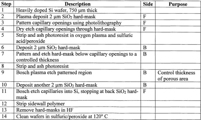
3.2 Fabrication
Three generations of MEA were fabricated having capillary diameters of 175, 25, and 12 ptm. [1] contains supplemental information detailing the microfabrication process flow. The important steps are listed here in Table 2 for quick viewing, with "F" denoting front-side processing and "B" for back-side:
Table 2. MEA Fabrication Process
Step Description Side Purpose
1
Heavily doped Si wafer, 750lim thick
2 Plasma deposit 2 ptm Si02 hard-mask F
3 Pattern capillary openings using photolithography F 4 Dry etch capillary openings through hard-mask F
5 Strip and ash photoresist in oxygen plasma and sulfuric
acid/peroxide
6 Deposit 2 Im Si02 hard-mask B
7 Pattern and etch hard-mask below capillary openings to a B
controlled thickness
8 Strip and ash photoresist
9 Bosch plasma etch patterned region B Control thickness
of porous area
10 Deposit another 2 pm Si02 hard-mask B
11 Bosch etch capillaries into Si, stopping at back Si02 hard- F mask
12 Strip sidewall polymer
13 Smooth capillary walls in 10:3:1 acetic, nitric, and HF Reduce hysteresis
acid for 4 min, rinse and spin dry and contact line
____ ____ ___ ___ ___ ___ ___ ___ ____ ___ ___ __ ___ pinning
14 Grow 100 nm SiO2 through thermal oxidation at 10000 C First dielectric
layer
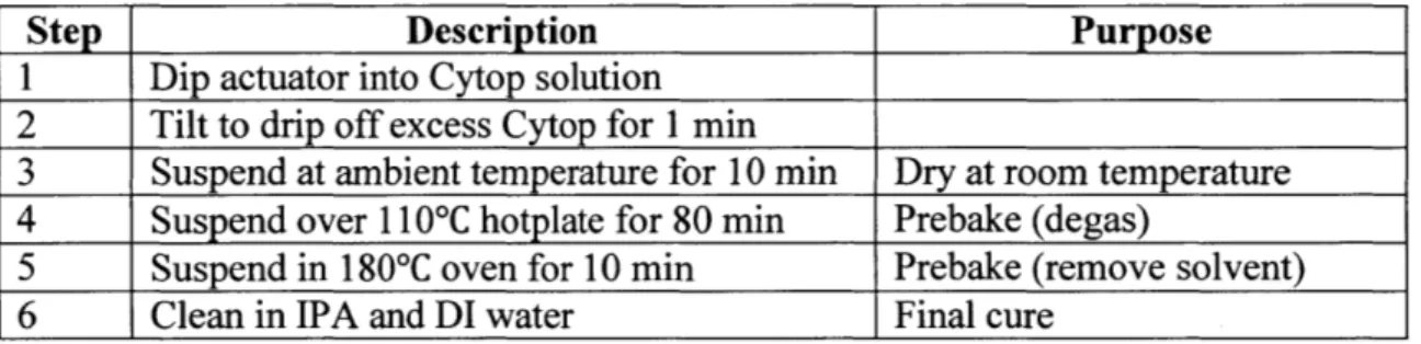
The wafer was diced into actuator samples measuring 20 mm x 20 mm, centered on the capillary region. Next the individual samples were dip-coated in Cytop CTL-809M (Asahi Glass Co., Ltd.), an amorphous fluoropolymer, to form the second hydrophobic dielectric layer above
Si02. Cytop was diluted in Fluorinert Electronic Liquid FC-40 (3M) for a coating thickness tCT
of 80 nm. The Cytop concentration (P for different plates of capillary diameter D was calculated as
D2 _ (D - 2tcT)2 4
tCT
D2 D
The dip coating process is described in Table 3.
Table 3. Cytop Dip-Coating Process
Step Description Purpose
1 Dip actuator into Cytop solution 2 Tilt to drip off excess Cytop for 1 min
3 Suspend at ambient temperature for 10 min Dry at room temperature 4 Suspend over 1 10*C hotplate for 80 min Prebake (degas)
5 Suspend in 180*C oven for 10 min Prebake (remove solvent)
6 Clean in IPA and DI water Final cure
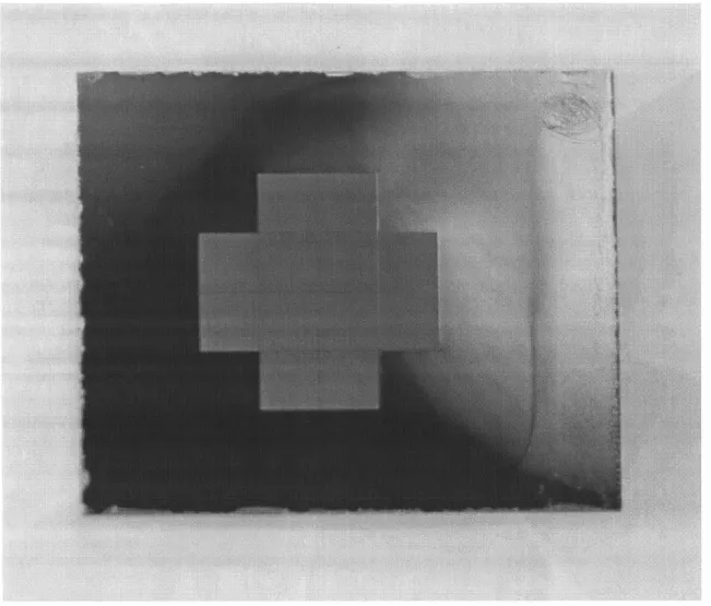
Figure 2 shows a 25 ptm D actuator plate after dicing and coating. The top-right corner has been scribed to remove the dielectric, allowing room for electrical connection during testing. The etched capillary portion is cross-shaped and the multi-color hue results from the Cytop coating.
Figure 2. Coated Actuator, 25 tm D
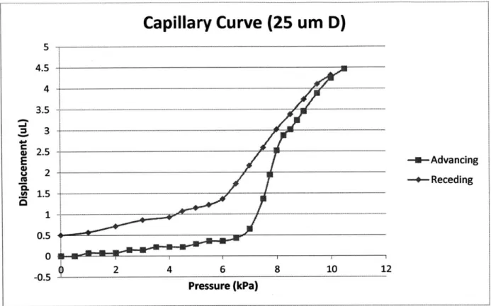
The capillary curve is a profile that shows the relation between back pressure and water penetration through the actuator's capillaries. The profile was acquired by steadily raising the back pressure and measuring the movement of a hydraulically linked oil-air meniscus. Upon reaching the bleed through pressure Pbt, the back pressure was gradually lowered back to zero. No voltage was applied to obtain the capillary curves. A representative capillary curve for 25 ptm
Capillary Curve (25 um D)
4.5
.- - - ---E -u-Advancing --Receding 4.5 - - ---4 .- -... .. ... ...-- --- --... 0 2 4 6 (kPa) 8 10 .Pressure 12Figure 3. Capillary Curve for 25 pim D actuator
The bottom curve is obtained by increasing pressure incrementally with an advancing
meniscus, while the top curve is for decreasing pressure with a receding meniscus. The
discrepancy between the two curves is due to contact angle hysteresis likely caused by surface roughness inside the capillaries. It is not until around the theoretical P~ at 8 kPa that a significant amount of water penetrates into the capillaries.
3.3 Modeling
A power density scaling relation was derived for the MBA, followed by a dynamic actuation analysis to allow more accurate performance predictions. Optimization strategies are given as guidelines for future work.
3.3.1 Scaling
The governing relation for hydrodynamic flow in a closed channel is given by
Ps =
QR,
where the volumetric flow rate
Q
is proportional to a differential pressure Ps and inversely proportional to the total hydrodynamic resistance Rs. This is analogous to Ohm's law governing electric current and voltage, with the effort variable (voltage) replaced with pressure difference and flow variable (current) replaced with volumetric flow rate.For laminar flow (Re < 2100) of an incompressible fluid, the Hagen-Poiseuille equation gives the hydrodynamic resistance Rh through a cylindrical pipe.
128yL
7rD4
Here y is the dynamic viscosity of the fluid, L the capillary length, and D the capillary diameter. Because the MEA is made of N parallel cylindrical capillaries, its resistance Ract can be
calculated as
128ptL
act NirD4
To verify laminar flow, an order of magnitude estimate is performed:
Q
=AUwhere A is channel area and U is flow velocity. Order of magnitude values for a water-filled, 25 pm D actuator with N-104 capillaries gives a Re on the order of
Re=pUD pD Q pD Ps 4
Ity y A Rs N WDz2
10310~5 103
4
In steady-state, for a volumetric flow rate of constant magnitude, the maximum actuation frequency fmax based on the time it takes the meniscus to traverse the capillary length L is:
fmax 2Vd isp
2RsVdisp
NiwD2L
Vdisp = 4
Here
Qss
is the maximum flow rate and Vdisp is the actuator volumetric displacement. Beyond the maximum frequency fmax, the actual displacement diminishes. This is due to hydrodynamic constraints on the meniscus speed.Using fmax, the power density Sd can then be scaled as
Sd = Ecyc = 2Psfma
Tcyc Vact act
with energy per cycle Ecy, period Tcy, and actuator volume Vact. Substitution of parameters into the power density equation gives
y~ 2FRF
= 8piL2
with resistance fraction FR = RactiR, and volume fraction Fv = Vdisp/Vact. At FR = 1, the system is unloaded. Fv is a function of the overall porosity of the actuator, which is the capillary volume normalized by the overall actuator volume. The maximum porosity for hexagonally arranged cylindrical capillaries is 91%.
The scaling result assumes:
- Pressure fraction Fp = = 1 or s =2
Pmax 2 D
- Displaced volume Visp = N4rLD2
4
- Dynamic viscosity of water is used pNaCl = '' 6Pdecane
- Dielectric thickness Td and roughness are negligible, Td D
- Instantaneous steady-state response
IQ, I
= constantGiven these assumptions, the result agrees with the scaling relation derived in [1].
ylOD2F2FFV Sd = 2pef L( L + 4D)(D + 2Td)2
For fixed aspect ratio capillaries, power density scales as 1/D2. This is achieved with a
smaller device size Vact but in exchange for less displacement volume Vdisp.
It has been demonstrated in [1] that downscaling capillary D leads to higher power density. Figure 4 plots power/strength density for actuators with three different capillary D sizes:
---. I I -;1- - -11 1 I-- --- --- -II- ----- -..I_ _.
E
SOW UO1000--10:0
1:0
0.1
0.01
1E-3
IE-4
1E-5-0.
I
Expected S (RIR =1/5, L/D=10) MS
measured at
f
d ma1
10
100
Capillary
Diameter (gm)
1000I
Figure 4. Power Density Scaling Trend [1]
3.3.2 Dynamic Response
In reality, the meniscus extension and retraction through the capillaries does not occur at a steady flow rate, but rather accelerates approaching a steady-state velocity. As capillary D is scaled down, the acceleration phase becomes a significant factor in the time it takes for full actuation to occur. For higher accuracy in modeling fmax, a dynamic model accounting for inertial effects was developed with the following assumptions:
i) meniscus motion stops upon reaching the capillary ends ii) constant driving pressure,
I
IP
= Pmax/2iii) ideal cylindrical capillary geometry, VdiSp = NL7rD2 /4
33
II
Strength density of
biological muscle
An enabling factor of systems analysis across multiple domains is the parallelism found between their "effort" and "flow" variables. In this case, these similarities allow the application of electrical circuit analysis to hydraulic analysis. The hydraulic system contains an inertia and resistance, and hence can be modeled as an LR-circuit, with pressure as the effort variable and volumetric flow rate as theflow variable. When pressure is applied at time t = 0, the flow rate can be stated as P / t
Q
(t) = -( 1 - e- =Qss(1
- e T) Rs pL A RS = Ri = Ract + Rother I -RThe hydraulic inertia I decreases as the fluidic channel expands to contain more fluid, which may seem counterintuitive. This is because pressure is a distributed areal force and a slug of fluid is easier to accelerate in a wider channel.
The system time constant -c is a measure of the system's reactance to pressure changes. It takes a time of roughly t = 3r for the system to reach steady state, during which the average flow rate is roughly two-thirds the maximum, steady-state flow rate.
Q(3r) = 0.95Qss
N
T
Q(t)dt
Qavg =
3-i:
= 0.683Qss-For an infinitely long capillary, the average flow rate approaches Q,. However, in smaller capillaries as in the MEA, the meniscus movement occurs predominantly within the acceleration phase.
trill is the time it takes for the meniscus to travel across the capillaries, producing an overall displacement Vaip and can be solved as follows:
t P t t t
V(t) = Q(t)dt = (t + e ii - ) )0 = Qss[t + T(e-T - 1)]
VdisP+=til+Te i
Recognize that Vdisp 1 SS Qss 2
fmax
trill = tSS + T + [W (-e k -+'))
Here the Lambert W function has been used for simplification. The Lambert W function is useful for solving delayed differential equations. It is the function W(z) satisfying
W(z)ew(z) = z
For real values of z, W(z) takes on two different values from - < z < 0. In the
e
principal branch used in modeling, the range - z 0 leads to -1 W(z) 0. In Figure 5,
e
Key
W. [Z1
N
13--05 0 0.5 1 1,5 Z 2.5
Figure 5. Lambert W function [15]
When -* 0, the result is simply tf ill = tss. As tssT/ -> o, t il deviates from the
steady-state approximation and becomes larger, meaning acceleration plays a larger role in tf ill
as D shrinks according to the scaling,
ts 1
T D2
Finally a more accurate fmax* can be predicted,
1 1
fmax*
2tf
ill 2 [tsS + r + TW e
3.3.3 Optimization
inertia L This can be done by reducing the length and increasing the diameter of tubing,
capillaries, or other components. The contribution from highly resistive segments of hydraulic circuits can also be mitigated by adding parallel paths. The equivalent resistance RAB of parallel loads RA and RB are calculated as:
RA= RARB
RA+ RB
For example, the MEA has capillary diameter D on the order of microns, but the overall
Ract is not excessive due to having N (0-10) parallel flow paths.
According to the maximum power transfer theorem, the greatest power is delivered to the load when the load impedance is matched with the source (actuator) impedance. For future systems, load matching should be designed for when practical.
Rsystem = Rsource + Rload
RioadiRsource 1 WIoad/Wmax -+ 1
For maximum efficiency, the ratio of source to load impedance should be minimized.
Rload 1
Rioa= + Rsource 1 + Rsource/Rload
3.4 Experimental
The experimental setup is depicted in Figure 6. The actuator plate is clamped inside a metal test assembly. On the oil side, the assembly is attached to a measurement tube the observe decane-air meniscus movement, which indicates volumetric displacement. At the top of the assembly is a junction linking the actuator to tubing that leads to a manometer. The manometer is the source of back pressure to the actuator, but it can be a significant contributor to resistance
provide a pressure source closer to the actuator. A hydraulic accumulator is a device that uses compressed gas or a spring to accumulate potential energy, and is commonly used to store pressurized fluid. It can be thought of as a hydraulic capacitor that can quickly adopt the pressure set by the manometer. According to the ideal gas law, as long as Vdip does not cause the air within the accumulator to undergo large changes, the accumulator can supply a near-constant pressure and can even replace the manometer after its pressure is set.
mRT
PaCU Paccum =v
-PaccumVair = constant
The accumulator used here does not supply a large pressure head due to height change, so most of the pressurization comes from the compressed air.
Manometer High speed
Pb
pyh
tI
Accumulator Fluid; Displacement h l Power supply Valve Va + Decane M Water Actuator camera images Actuated Not actuated easurement tube High speed cameraFigure 6. Experimental Setup
IIII
1.
[11
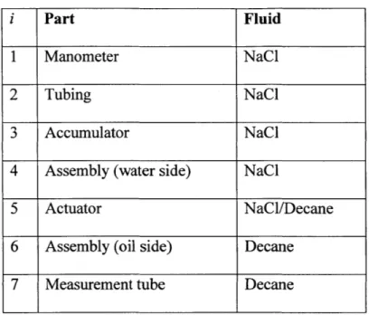
ii ___011ORL-The setup consists of the following components filled with their respective liquids, in Table 4.
Table 4. Parts of Actuator Test Setup
i Part Fluid
1 Manometer NaCl
2 Tubing NaCl
3 Accumulator NaCl
4 Assembly (water side) NaCl
5 Actuator NaCl/Decane
6 Assembly (oil side) Decane
7 Measurement tube Decane
With length and diameter known for each ith component, the total system resistance was calculated as
RS= Ri
For the pressure sources, the manometer and tubing are parallel to the accumulator, and the equivalent resistance for these sections was calculated accordingly. Using the dynamic model developed earlier, fmax* can be approximated.
In testing, the key operating parameters were the back pressure, actuation frequency, and voltage. Experimentation over various parameter combinations revealed that higher back
pressures and voltages produced greater Vdisp and power. Pb should be at least half Pmax. At frequencies beyond the predicted fm,, the observed displacement gradually decreased, as expected. Though a higher voltage initially produced larger displacements, it caused a relatively
quick degradation in displacement over time. Detailed experimental and analysis procedures can be found in [1].
3.5 Reliability
It was noticed that the actuation volume would degrade slightly over time, calling into question the reliability of MEAs. Tests were performed on 25 tm D plates at various voltages to observe repeated electrowetting performance over tens of thousands of actuation cycles. Two actuation cycles result from each electrical cycle, with displacement happening at the waveform peak and trough. Figure 7 shows the reliability test results for sine wave excitation below
fmax* 40 Hz and Pb = 3.5 kPa.
Reliability Testing
3 2.5 2 -- 17V 18.5V E 1.5 - 1 --- 20V b -22V a 0.5 -22V b 0 0 10000 20000 30000 40000 50000 60000 70000 Actuation CyclesFigure 7. Reliability Testing
a considerable initial displacement around 2 p.L, only slightly below that of the higher voltages. Over many cycles, the actuation curves corresponding to 20 V and below flattened out toward a displacement of about 1.7 ptL, with little signs of further degradation beyond this range.
The suspected reason behind degradation in reversible electrowetting is charge trapping within the Cytop dielectric, which effectively decreases the average applied voltage across the actuator. A similar degradation is observed by [16], who tested repeated electrowetting on three different dielectric fluoropolymers, with Cytop having the best performance. They propose that the electrically leakier Cytop allows trapped charges to diffuse more easily. Another contributor to degradation is local dielectric breakdown at higher electric fields, such as for the case with a
22V applied voltage where steep degradation rates are observed.
As long as higher actuation voltages above 20 V are not applied over long durations, MEAs remain a consistent and reliable option worth exploring for microrobotics.
Chapter 4
Squid Design
After experimentally verifying the microhydraulic electrowetting actuator's potential for reliable actuation, the next step was its implementation into a mini-robotic system. The design goal was to create a robotic platform to demonstrate MEA-driven propulsion at velocities comparable to marine organisms at the centimeter length scale. Throughout the design process, emphasis was placed on fabrication simplicity which led to the adoption of additive
manufacturing processes. It will be seen that individual component design variables have an interconnected influence on performance, despite the linear fashion in which the component
design process is presented. Multiple variants were proposed but only the final design is presented here. The following discussion of the squid design consists of concept generation,
analytical modeling, and system development.
4.1 Inspiration
Since microhydraulic actuators are particularly well-suited for fluid-immersed
environments, inspiration for a mini-robotic platform was naturally drawn from the sea. Animals belonging to the Cephalopoda class, including squid and chambered nautiluses, are known to utilize a combination of undulatory fin motion and jet propulsion for biolocomotion, depending on the specific task. Studies of biolocomotive efficiency of long-finned and brief squid through ontogeny show that paralarvae rely almost exclusively on a high-frequency, low velocity jet for movement until growing to a 1.5 cm mantle length, reaching speeds of up to 16 cm/s [17]. A
peak propulsive efficiency of 40% is achieved at 1 cm mantle length [18]. Such studies confirm jet propulsion is a viable locomotion mechanism at centimeter length scales and below.
4.2 Propulsion Scheme
Jet propulsion in squid can be described in part by momentum transfer via diaphragm pumping. In a diaphragm pump, a reciprocating diaphragm first deflects to increase the pump chamber volume, which decreases the internal pressure causing fluid to flow inwards through an inlet (suction phase). Next, the diaphragm deflects in the opposite direction, reducing the
chamber volume and ejecting fluid through an outlet (pump phase). Check valves maintain directionality of the flow by preventing backflow. Without check valves, a squid expands its mantle to suck water into its body through an aperture. When the mantle contracts, a water jet is
expelled through the same aperture, now constricted, at a higher velocity than it entered with. The momentum difference between the incoming and outgoing jets imparts a net propulsive force onto the squid. It is recognized that other effects play a role in squid jetting, such as vortex ring interactions and induced coflow, but these are assumed to play a less significant role when analyzing pulsatile jets through two designated (inlet and outlet) orifices.
In similar fashion to the diaphragm pump, the MEA can be used to hold a "liquid diaphragm" that sucks in and expels fluid through a chamber. The positioning of passive check valves at the inlet and outlet will ensure unidirectional flow while eliminating the need for active control, thus reducing complexity. The orifice diameters and valve orientation can be designed for the jet to impart optimal thrust.
4.3 Actuator Configuration
When analyzing possible actuator configurations for the squid, valuable insight was gained from research in synthetic jet actuators (SJA). SJA are used primarily in aeronautical systems for flow control, heat transfer, and jet vectoring. They form jets "entirely from the working fluid of the flow system in which they are deployed and, thus, can transfer linear momentum to the flow system" [19]. Double-acting operation is commonplace for SJAs, and is described as an actuator that "consists of two... chambers, from which fluid is displaced by the opposite sides of the same diaphragm" [20], such that the chambers are pumped intermittently in anti-phase with each other.
In designing the mini-robotic squid, two actuator configurations were considered:
Configuration A is a single acting arrangement identical to a diaphragm pump, consisting of a single actuator covered by a deformable membrane that flexes to accommodate volume displacement. Throughout expansion and contraction, the membrane supplies a relatively constant back pressure to the actuator. On the other side of the actuator plate is the pumping chamber, or mantle, with check valves positioned at the inlet and outlet to dictate the flow direction. The membrane can supply positive pressure or negative pressure, depending on the arrangement of oil and water (NaCl). An example of this configuration is shown below.
Membrane Press urized Chamber Actuator 1HI Pumping Chamber
Check Valves, open
Nozzle and closed (X)
Figure 8. Single-Acting Arrangement
Configuration B is a double-acting arrangement that uses two actuators, symmetric about a shared pressurized water chamber. There are two separate but parallel pumping chambers, each
adjacent to an actuator. The actuators operate in anti-phase: as the first (VOFF) expels water, the second (VON) takes in water with an enhanced back pressure of Pmax supplied by its inactive counterpart, and so forth. No deformable membrane is needed since back pressure is derived from the actuators' capillary pressure.
The comparative advantages of the double-acting configuration are examined: Advantages
-allows for simple, symmetric design -eliminates need for deformable membrane -higher potential volume efficiency 17olume
-higher theoretical back pressure and driving pressure Disadvantages
-larger device size, more skin friction drag
-possibility of complex dynamic coupling effects between the actuators Volume efficiency lvolume is defined as the ratio of actuator active volume to total device volume with n actuators.
Vactive faVdisp
Vtotai Vtotai
The supporting structure consists of valves, the pumping chamber, and a shared water chamber with a volume of at least Vdispiacement. The maximum volume efficiencies for both
configurations are calculated as
Vactive
lvolumeA =_ Vactuator + Vsupport + Vdisplacement
2Vactive
volumeB 2
(Vactuator + Vsupport) + "displacement
Having a shared water chamber reduces the total volume in configuration B by Vdisplacement-Otherwise, as in configuration A, there would need to be a membrane with minimum capacity
Vdisplacement to accommodate volumetric displacement, per actuator.
Another benefit of double-action is having back pressure supplied by capillary pressure
Pmax from hydrophobic capillaries, which equates to an increase in driving pressure by a factor
of 2 in theory. Under configuration A, the pressure fraction is close to Pmax, to allow equal
2 mx
magnitude of driving pressure in meniscus extension and retraction through the actuator plate. In double-action, as long as an oil-water interface remains in the inactive actuator's capillaries, a back pressure of Pmax is delivered to the active actuator.
1
Configuration B was selected for its advantages in volume efficiency and pressure. Without the need for a flexible membrane, fabrication is made simpler while the additional complexities seem manageable and do not drastically change the fundamental operation of the squid.
4.4 Stacking Architecture
The design process was focused on optimizing the propulsive force, thus maximizing velocity. Given the flat form factor of the MEA plates, it was logical to adopt a stacking
approach to building the squid, where components are laid horizontally on top of each other, as in Figure 9.
Flap valves (black)
Mantle
~ -. Gasket
Actuator (blue)
Electrode (orange)
Figure 9. Double-Acting Squid Robot (back)
The robotic squid is comprised of a stack of individual components. Two parallel pump chambers, or mantles, lie symmetrically about a shared water chamber, which is located between dual actuators operating in anti-phase. The stack is compressed together by heat-shrink tubing and
m ~
-hydraulically sealed at the gaskets. A buoy is attached to the squid for flotation when it is immersed in decane. Both the compression tubing and buoy are not pictured in Figure 9.
A V_1= OFF Ground V_2= ON
A&
A
Afi
. ... ----Figure 10. Double-Acting Squid Robot (side)
In Figure 10, the fluid flow path can be seen running through the components in the following order: inlet orifice, inlet valve, top mantle cavity, top actuator, water chamber, bottom actuator, bottom mantle cavity, outlet valve, and outlet orifice.
In subsequent sections, the design considerations and development of each subcomponent are discussed in detail, beginning with the actuator.
.-
4.5
Actuator
The 25 pm D actuators were selected to drive the squid. The selection of an actuator fixes the power density, driving pressure, displacement volume, and general size of the squid. While higher pressures are produced at 10 pm D, there is only half as much displacement volume, which may complicate the check valve design. The 25 pm D actuator dimensions are given in Table 5 and shown in Figure 11.
Table 5. Actuator Specifications
Capillary D 25 im
Capillary stop D 10 Pm
Capillary Length L 200 Rm
Aspect Ratio L/D 8:1
Actuation volume Vdisp 5-7 L
Number of capillaries 60k
Pmax theoretical 8 kPa
Figure 11. Actuator, 25 um D (backside)
The cross-shaped porous region in the middle is composed of 12 smaller porous squares measuring 2 x 2 mm2 that lie within the area of an 8 x 8 mm2 square. The front of the actuator plate is flat, while the back contains an indented region resulting from the backside etch, thinned down from 450 tm to 200 prm. The indented region on the backside extends outward 0.5 mm from the capillary squares, falling within the area of a 9 x 9 mm2 square. The longest diagonal across the indented region is 10.3 mm. This poses a requirement that the gasket sealing the
The actuator dies are diced from 20 x 20 mm2 down to 18 x 15 mm2. This was done to
leave enough assembly tolerance for gasket placement around the active region and to offer more area on the sides when securing electrical interconnections to the actuator plates, which is
discussed later.
4.6 Electrical Waveform
Although the double-acting actuators operate in anti-phase, the voltage signals applied to them must be in quadrature, shifted by 900. This is depicted in Figure 12 where two 20 V sine waves are shown with five time markers. The orange wave precedes the blue waveform by a quarter-cycle, or 90*. At point 1, the "blue actuator" receives Vblue = 20V from the blue
waveform, and is fully actuated in the ON state. At the same time, Vorange = OV and the "orange actuator" is in the OFF state. At point 2, a quarter cycle has passed, and now the blue actuator is OFF (Vblue = OV) while the orange actuator is ON (Vorange = -20V). During the transition from point 1 to 2, the blue actuator forced water out of its capillaries at pressure Pmax into the orange actuator which then had AP = 0. Continuation of this double-action cycle results in this same actuation pattern.
Figure 12. Quadrature Waveforms
A quadrature circuit was constructed using a sine wave from an arbitrary function generator (Hewlett Packard 8116A Pulse/Function Generator 50 MHz) as the input signal. Data was acquired by an oscilloscope (Teledyne LeCroy WaveRunner 104 MXi 1 GHz Oscilloscope). A second voltage waveform in quadrature was generated by feeding the input through a first-order all-pass filter. An all-pass filter introduces a phase shift at unity gain. Only a single op-amp is needed; an OPA445 high-voltage operational amplifier was used in the all-pass filter. For a specific frequency a) = 27Tf = 1/RC, the input waveform undergoes a 90' phase shift. The
4.7 Modeling
The performance prediction of the robotic squid is meant to provide an expected range for the squid velocity U5quid, and is based on the same method used for modeling the actuator. In
the double-acting configuration, the serial fluid path passes through the squid as shown in Figure 10.
With the two actuators operating in anti-phase, the driving pressure to one actuator is supplied by the positive expelling capillary pressure from the other actuator. Since fluid displacement Vdip is the same in both actuators, P will become zero when the receding
meniscus in the inactive actuator reaches the capillary openings. Because both actuators share the same displacement, the advancing meniscus into the active actuator cannot be driven past the capillary stop, thus water bleed-through is improbable. Bleed-through is, however, possible in the case that a significant number of capillaries in one actuator become clogged, such that for the other actuator the fluid intake per capillary increases beyond the capillary volume.
The back pressure is supplied by the actuator in which water is receding.
Pb ; Pmax
The system hydrodynamic resistance is calculated as
RS = Ri = 2Ract + 2ROrif ice + Rmantie + Rchamber + 2Rvaive For circular orifices of diameter d with mantle wall thickness t:
Rorifice - 1284 t
7wd4
An estimate of component resistances from preliminary testing shows that the check valve resistance Rvalve dominates Rs.
Propulsive thrust is derived from a control volume approach assuming no leakage,
constant jet velocity, and steady flow conditions for continuous operation. Modeling the squid as having outlet orifices oriented coaxially along the thrust direction, and inlet orifices orthogonal to the outlet orifices, the propulsive force can be simplified to
Fthrust = ?f(U2 - U1) = ?fUjet
r = pAU = p2Vdispfmax
Q = Aorifice Ujet
where rh is mass flow rate and
Q
is volumetric flow rate with Ujet as jet velocity. The factor of 2 in ?h accounts for double-action. The inflow enters through opposite facing inlet orifices and produces zero net momentum flux. The velocity U can be rewritten asUorif ice
Q
2Vdispfmax Ps= Aorif ice) Aorif ice RsAorif ice
Substituting for thrust gives
tf ill = Vdisp/Qss
Fthrust = p2 Vdisp RsA i = p2 Vdispfmax ()
2tf ill) Rorif ice) R Aorfc
Aorif ice = irdorificeI4
For maximum thrust, the orifice should be designed to maximize outgoing jet velocity. With a fixed mantle wall thickness, the orifice diameter should be decreased to increase jet velocity, up to the point where further shrinking of the orifice significantly increases Rs such that the jet velocity begins to decrease. With ideal valve checking performance, the orifice diameter should be set to satisfy the relation:
The peak velocity of the squid is reached when the drag force is equal to thrust. 1
Fdrag = 2 PoUsquidCA squid
Here Cd is drag coefficient and Asquid is the wetted frontal area. A drag coefficient of 1.15 was used for a short cylinder oriented perpendicular to the flow.
4.8 Mantle
The mantle is a covering that protects and provides structural support for internal components. The robotic squid's mantle pieces are located at the top and bottom of the stack architecture, though they do not completely envelop the inner components. The remaining components are sandwiched in between the mantle halves under compression tubing.
Several CAD iterations were created using SolidWorks, with the following design considerations:
-Size: Size should be optimized for drag and weight reduction, as the mantle is one of the heaviest parts of the squid assembly. It must envelop the entire active capillary region of the actuators, but shouldn't be much larger beyond that. There must also be room for the
check valves and orifices to fit onto the mantle.
-Shape: A more streamlined profile will help to reduce the drag force and increase squid velocity. Additionally, the inlet and outlet check valves are located inside and outside the mantle, respectively. A flat area should be designated for valve placement. Valves and orifices must be correctly oriented for efficient momentum transfer to the oil surrounding the squid. In order to concentrate the exit jet momentum, the outlet valve should be placed into a recessed valve fixture where the sidewalls confine the jet direction.
-Hydrodynamic resistance: This should always be minimized for maximal thrust. The channel in the mantle cavity should not be a major contributor to the flow path resistance, as it is one of the larger components. However, the orifice and check valve, which are both integrated with the mantle, are expected to be highly resistive.
-Wall thickness: The thickness of the walls must withstand pressures that are both internally generated and that result from outer compression. As long as the mantle is robust during the assembly procedure, thickness can be reduced. The mantle deflection under driving pressure P should not reduce the ejected volume.
-Interfacing: The gasket and compression tubing will be pressed against both sides of the mantle. Special features may be incorporated to help with the assembly process. Enough room should be left between the two mantle pieces for electrical connections to the actuators.
![Table 1. Major actuator characteristics [9] [10] [11] [12]](https://thumb-eu.123doks.com/thumbv2/123doknet/14722917.570904/19.918.86.839.322.625/table-major-actuator-characteristics.webp)
![Figure 1. Actuation Cycle [1]](https://thumb-eu.123doks.com/thumbv2/123doknet/14722917.570904/26.918.183.717.121.626/figure-actuation-cycle.webp)
![Figure 4. Power Density Scaling Trend [1]](https://thumb-eu.123doks.com/thumbv2/123doknet/14722917.570904/34.918.129.765.139.621/figure-power-density-scaling-trend.webp)
![Figure 5. Lambert W function [15]](https://thumb-eu.123doks.com/thumbv2/123doknet/14722917.570904/37.918.161.736.107.548/figure-lambert-w-function.webp)