ANALYSIS AND ERROR MODEL FOR A. TWO-DEGREE-OF-FREEDOM ELASTICALLY SUPPORTED TUNED GYRO
by
David Bruce Graham S. B., Oregon State University
(1970)
Submitted in Partial Fulfillment
of the Requirements for the Degree of Master of Science at the Massachusetts Institute of Technology
Cambridge, Massachusetts
June, 1972'
Signature of Author
Department of A.eronautics and Astronautics
Certified by
Thesis Supervisor I
Accepted by
Chairman, Departmental ommittek on Graduate Students
Archives
DEC 5 1972 FRA R1
ANALYSIS AND ERROR MODEL FOR A. TWO-DEGREE-.OF-FREEDOM ELASTICALLY SUPPORTED TUNED GYRO
by
David Bruce Graham
Submitted to the Department of Aeronautics and Astronautics on May 15, 1972, in partial fulfillment of the requirements for the degree of Master of Science.
ABSTRACT
The spinning rotor is supported by torsional elements in an elastically supported tuned gyro. These torsional elements create a positive spring restraint on the rotor. By spinning the entire support structure of the rotor at a "tuned" speed, the positive
spring restraints are cancelled by negative spring restraints created
from the dynamics of the spinning rotor and support structure. The
result is a freely supported rotor uncoupled from any case motion
inputs.
How the balancing of spring restraints is performed is shown for an Oscillogyro, a Hooke's Joint Gyro, and a multigimbaled gyro.
An error analysis for the multigimballed gyro is then given
with its error model for testing and a general description of a test procedure for testing the instrument.
Thesis Supervisor: Walter Wrigley, ScD
Title: Professor of Instrumentation and Astronautics
d. -
Acknowledgement
I wish to thank the personnel at the Charles Stark Draper Laboratory who made it possible for me to write this thesis.
Particularly, I want to thank Julius Feldman, Charles Lory, George Bukow, and Professor W. Wrigley for their constructive
criticism and guidance in writing this thesis.
I am particularly indebted to Mr. Robert I. Craig and to Teledyne Systems Company for their permission to make use of
theoretical material on a two-degree-of-freedom, elastically
supported, tuned gyro.
I also wish to thank my wife Christy, Dave Monzingo, Ron Miller, Bill Odonell, Mike Odonell, Bob French, Dennis Gill, Dave Batcheldor, and Ralph Owens for their encouragement and Miss Norma Wasser for typing the thesis.
This report was prepared under DSR Project 55-34010 sponsored by the National Aeronautics and Space Administration of the Marshall Space Flight Center through Contract NA.S 12-2033 with the Charles Stark Draper Laboratory of the Massachusetts Institute of Technology in Cambridge, Massachusetts.
The publication of this report does not constitute approval by the Charles Stark Draper Laboratory or NASA of the findings
or conclusions contained therein. It is published only for the exchange and stimulation of ideas.
-3-Table of Contents Page Introduction Basic Concept The Oscillogyro 3. 1 3. 2 3. 3 Section 4
Ideal Operating Condition Equations of Motion
Tuning Condition
Hooke's Tuned-Joint Gyro 4. 1 4. 2 4. 3 Section 5 5. 1 5. 2 5. 3 Section 6 6. 1 6. 2 6. 3 6. 4 6. 5 6. 6 Section 7 Section 8
Ideal Operating Condition Equations of Motion
Tuning Condition
Two Degree of Freedom Gyro with "n" Gimbals Ideal Operating Condition
Equations of Motion Tuning Condition
Errors for Multigimbal Elastically Supported
Tuned Uyro Mistuning
Mass and Quadrature Unbalance
Twice Spin Frequency Angular Oscillations of the Case
Damping forces due to windage Rotor Angular Offset
Anisoelasticity
Error Model for A Two-Degree of Freedom Tuned Gyro
Test Procedure for a Two-Degree-of-Freedom
Tuned Uyro References -4-Section 1 Section 2 Section 3 1 2 5 5 5 8 11 11 11 17 21 21 21 32 35 35 39 47 50 52 54 55 60 63
Principal moments of inertia of rotor about rotor x, y, z axes respectively.
Principal moments of inertia of the nth gimbal about xn, YnI Zn axes respectively.
ax, ay, aZ ax , ax, az Dxn, Dyn, D DD Fm j Kxn, Kyn
Rotor linear accelerations resolved along case fixed coordinate set.
Rotor linear accelerations resolved along rotor
fixed coordinate set.
Damping coefficients associated with the torsional flexures of the nth gimbal about xn, n axes. Damping coefficient due to rotor drag
Gyro figure of merit.
Torsional stiffness of flexures for the nth gimbal about gimbal xn and yn axes respectively.
Translational stiffness of rotor to shaft suspension
along rotor fixed axes. Mass of rotor
M
Mass of the nth gimbal.
-
5-LIST OF SYMBOLS
A, B, C
Mx, My Mz
Mx, MyS Mz
N
No
n
Externally applied moment to rotor resolved
along shaft fixed coordinate set.
Externally applied moment to rotor resolved along
case fixed coordinate set.
Speed of shaft rotation relative to case. Gyro tuned speed.
Number of gimbals
Quadrature coefficients resolved along rotor
fixed axes.
LaPlacian operator. Time.
Rotor to case drag torque.
Moment applied to the nth gimbal the gimbal xn axis.
Moment applied to the nth gimbal the gimbal n axis.
by the rotor about
by the rotor about
Shaft reaction moment exerted on the nth gimbal about the gimbal xn axis.
Shaft reaction moment exerted on the nth gimbal about the gimbal Yn axis.
- 6-qx qy s t TD Tyn
Angle between xn axis of the nth gimbal and x' axis of the rotor.
Angular velocity of rotor relative to shaft resolved along rotor fixed coordinate set.
Angular velocity of rotor relative to case resolved along case fixed coordinate set.
Absolute angular rates of gyro case resolved along
case fixed coordinate set.
Absolute angular rates of the shaft resolved along
shaft fixed coordinate set.
Absolute angular rates of rotor resolved along
rotor fixed coordinate set.
Absolute angular rate of the nth gimbal resolved along the coordinate set fixed to the nth gimbal. Phase angle of vibration in space domain.
Phase angle of vibration in time domain. Angular frequency of vibration.
Angular frequency of nutation.
Time constant at nutation frequency.
Gyro time constant.
-7-4j1
x lAwU I Wt UJYxj I Ag I W:L uo a, I rkx Iey3 Lo YI I~ W I L LIntroduction
A freely supported gyro is a spinning mass mounted on its supported and protecting case so that the case can be turned and translated in any direction without causing torques that disturb the
angular orientation of the rotor axis relative to inertial space.
One design approach has been to find a substitute for the rotating wheel. Thus there are gyros designed with various kinds
of spinning fluids, vibrating masses, nuclear and atomic inertia
7,8,12
effects, and laser frequency difference effects. These
designs have had some good performance but thus far none have been operationally available in practical sizes and power ranges.
The other approach has been to refine the output axis support to the rotating mass. In this class of gyros we have the fluid,
electrostatic, electromagnetic and gas bearing suspensions. 4' 9 The rotating suspension of the elastically supported tuned gyro that
this thesis talks about is in this class of instruments. Over the
last decade the elastically supported tuned gyro has been developed with simplicity, low cost (25% of conventional floated gyro)2 and long term drift rates of 0. 01 degree per hour, to give a promising approach for future low cost inertial quality gyros.
This thesis will present the basic concepts of elastically
supported tuned gyros with particular emphasis on the two-degree-of-freedom elastically-supported tuned gyro. It will also develop the
instrument's error model and present a test procedure for testing
Basic Concept
If a gyro with a rotating mass is to keep a fixed direction in inertial space (it is then a free gyro), the support structure for
this rotating mass must apply no torques to the rotating mass when
the gyro is moved relative to inertial space.
Conventional approaches to achieve this freely supported rotating mass have been to mount a rotating mass through a number of gimbals to give it the required degrees of freedom. For a
two-degree-of-freedom gyro the support is as shown in Figure (1). This type of approach creates the following problems: (1) The gimbal
bearing friction is a distrubance torque to the rotating mass,
(2) Mass unbalance torques on the rotating mass occur from the
spin motor mounted inside the gimbals. The stability of that unbalance is directly related to the gyro acceleration drift stability. (3) The electrical leads needed to carry wheel current from one gimbal
to another can create elastic restraint torques on the spinning rotor.
An alternate approach used in the elastically supported tuned gyros is to support the spinning rotor from the inside out and rotate the whole suspension by a spin motor connected to the shaft as shown in Figure (2). Some advantages in this approach are that: (1) no mass unbalance torques occur from the spin motor, (2) no electrical
power is transferred through the gimbals, (3) no bearings are needed to give the rotor its degrees of freedom. Thus with this method of motor suspension, only two restraints occur on the rotating mass. One of these restraints is due to the torsion elements and creates
-9-Spi n
Rotc
Gimbals
Figure 1 - Two-Degree-of-Freedom Conventional Support
. - _
Spin
Axis
Shaft
Axis
yr U od:o
Figure 2 - Rotating Suspension Configuration
-10-Axis
an expected positive spring torque between the rotor and shaft. The second restraint, and the key point in the basic concept of these gyros, is that a negative spring torque is created between the rotor and shaft due to the dynamic behavior of the rotating
mass. This negative spring restraint is proportional to the rotation
speed squared and can therefore be used to compensate for the positive spring torque, produced by the restraint of the torsion element, by rotating the entire system at a selected speed ("tuned" speed) that balances the two restraints. Perfect balancing of these two restraints on the spinning mass results in a freely supported spinning mass -- the condition we are trying to achieve.
A better understanding of this concept will be developed in the following sections after considering how this condition of
balancing spring restraints is performed for some specific gyros.
-11-The Oscillogyro 3. 1 Ideal Operating Condition
In the oscillogyro, as shown in Figure (3), a
single-degree-of-freedom structure supports the rotating mass. 1 In this instrument,
the plane of rotation of the sensitive element should ideally remain fixed in inertial space for small angular rotations of the instrument about axes perpendicular to the shaft. This motion between the
oscillobar and a surrounding case is sensed by pick-offs and used
by some torquing mechanism to realign the oscillobar to a nulled position. The pick-offs can be arranged in two pairs in each of four quadrants to measure the proximity of the bar to a reference
plane on the instrument. One pair of pick-offs measures displace-ment of the bar about an axis and a quarter of a revolution later the other pair measures displacement of the bar about an axis at right angles to it. The instrument can then be regarded as a two-degree-of-freedom gyro by working on a time sharing-basis.
To achieve this ideal operating condition the resultant torques on the sensitive element must be zero when the shaft is rotated through this small offset angle about an axis perpendicular to itself. It will be shown in the derivation of the rotor's equation of motion how the dynamic torque acting about the suspension axis will be used to modify the torsion torque of the suspension element to achieve the ideal operating condition.
3. 2 Equation of Motion
A beam, called the oscillobar, is supported about the torsion element axis, y', and free to rotate about that axis through a small
12-%.i__ spin axis of motor
Ilastic Hinge
tor
Figure 3 - Features of Oscillobar
Z' Z
Axis
Y'Y,
Drive Axis
Figure 4 - System Axes
-
angle, . The entire support structure is rotated at a rate )
about the drive axis, Z, as shown in Figure (4). The entire shaft and support structure is then rotated at a rate about an axis Y which is perpendicular to the drive shaft and fixed in the gyro case surrounding the entire system. The axes x y z are fixed in the shaft and rotate with respect to the case fixed set X Y Z at a rate N about the case Z axis. The x'y'z' set is fixed in the
oscil-lobar along its principal axes of inertia.
The angular velocities of the oscillobar with respect to
inertial space along oscillobar axes are
Wo, c Si
siCO5 Go
e - 'Swe
(3. 1)
Ws, = .cos' +
UJw S Vsi\p SnrG 4qCoSO
where wx,, wy,,Wz, are angular velocities of the oscillobar with
respect to inertial space.
Using Euler's equations of motion for a rigid body to describe the motion of the oscillobar about the y' axis, one obtains
T2-
X1,Q
(3.2)
where T2 is the torque applied about the y' axis and A, B, C are the principal moments of inertia of the oscillobar.
Substituting equation (3. 1) into (3. 2) gives
*@
c (C-A)(l> -
i
rSipl swne Co5o ~TA
-'(
C OS3(3.3)
-14-The torque T2 contains a contribution from the spring torque, the windage torque, and a torquing mechanism torque. Writing
-
e
-Ce +Tz'
(3. 4)where T2 is the torquing mechanism torque, KG is the spring torque, C4 is the windage torque, and substituting into (3. 2) assuming that
))
>>,
~S ~n-e
A, and cos5- A, one obtainsO
Ace
++K+ (C-A)l TK cose'\ + ( C-A)Sril (3 5)Finally assuming that -\ is constant
Qi
= N) , the equation of motion for the oscillobar becomes6
tcG
tis(c-)Nt~e
- T+'-eB cosNt +( 6C-A
l\Nt (3. 6)where T2 may have any designated variation in time. 3.3 Tuning Condition
The response of the gyro to a steady rate of turn, ~ =-L and no control torque input, is
B
-- c +e J (C-A)Nz - (8+C-A) CLCA s1n Nt (3. 7) The desired response of this system to the steady rate input isobtained by making K = (A + B - C)N2 (i. e. balancing the torsional
restraint by the dynamic restraint).
The equation of motion for the undamped case becomes
+
NG0
( C - A)/B L N so Nt (3. 8)15-4.
with expressed as ( GO, G as initial conditions)
(sB+C-A) (3. 9)
O
=os
.n (.Nt
+) - (6+C
)LcoS Nt
-'t
(3)
The first term is small compared to the second term for
A << B, C,and 0 _ 0. 5 degrees. For this condition, the amplitude of the deflection is proportional to the input rotation, lt. ,
thereby permitting a sensing element (pick-off) to detect inertial rotations of the gyro case.
It can also be seen that the phase of the 0 response (again neglecting the first term) is exactly 900° out of phase with
(B + C - A) J-L N sin Nt, the dynamic driving torque, causing the oscillobar motion. When (B + C - A) = 1 , the plane of rotation of
2B
x' would lag the plane XY by exactly the rotation of XY, thus x' or the oscillobar, rotates in a fixed plane in inertial space. This is assuming that (A + B) = C and K = 0. This condition can only be achieved approximately by concentrating the mass of the oscillobar near the axis x' so that A << B and B ' C and keeping the value of K as small as possible. The absolute movement of the plane of
rotation is then minimized and satisfies the condition for a free
elastically supported tuned gyro. Note again the tuning condition was found by making the torsional restraint equal to the dynamic restraint or by tuning the undamped natural frequency of the system to the
system's rotation speed.
A physical picture of how the oscillobar stays fixed in inertial space is seen in Figure (5).
16-The plane of rotation of the bar stays fixed in inertial
space, but has a cyclic rotation (with amplitude equal to the shaft's offset angle) with respect to the shaft fixed coordinate set.
Fixed
Plane
90 0
180°
I
./
Figure 5 - Fixed Plane of Oscillobar Oscillation
-
Hooke's Tuned-Joint Gyro 4. 1 Ideal Operating Condition
This gyro's suspension gives the sensitive element two
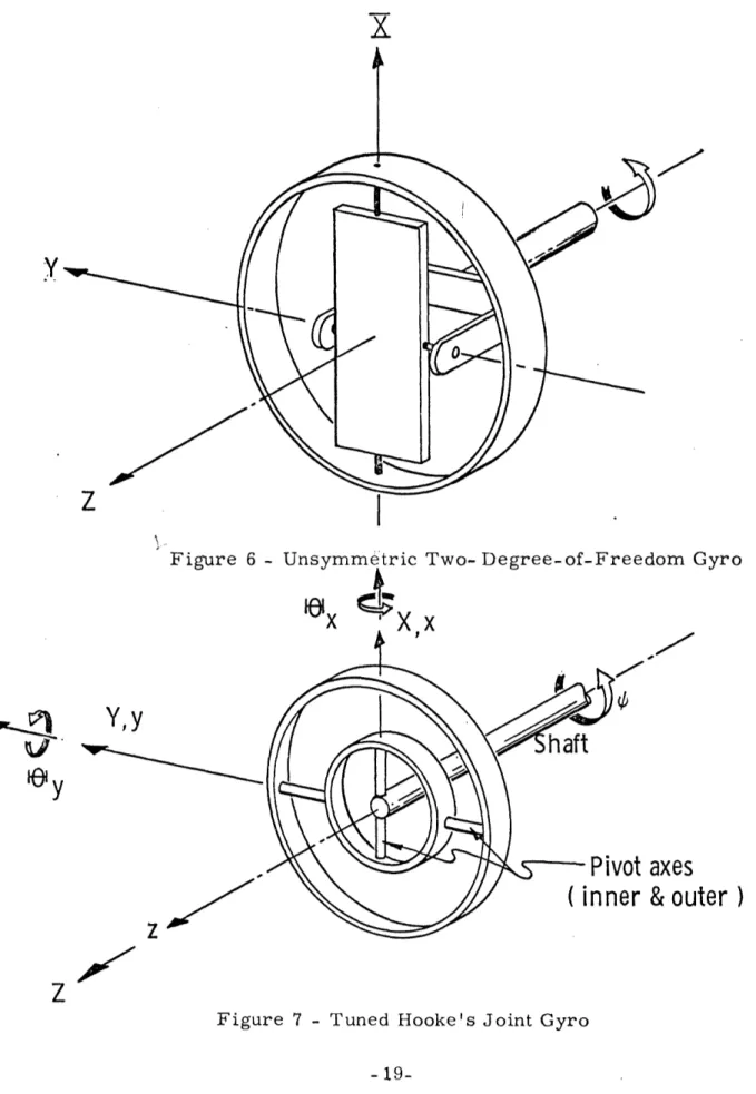
degrees of freedom plus increasing the gyro's angular momentum by adding an extra ring outside the oscillobar as shown in Figure (6). This arrangement can be simplified to the symmetric representation in Figure (7).
For this instrument, the ideal mode of operation is to have the rotor spin axis remain fixed in inertial space when the shaft is rotated through some small angle about an axis perpendicular to the shaft. This small rotation of the shaft with respect to the
inertially fixed rotor, is then a direct measure of the case's motion with respect to inertial space. This ideal mode of operation is achieved by correct "tuning" of the positive spring restraints of the torsion members to the negative spring restraints caused by the
rotor dynamics.
4. 2 Equations of Motion
For ideal gyro performance the torques that will be transferred to the rotor when the case is rotated through small angles A
or 19y with respect to the rotor must equal zero. As a
simple model of this system, assume the torsion elements are replaced by perfect frictionless pivot bearings.
Consider a system of Cartesian axes fixed relative to the gyro case such that the Z axis coincides with the driving shaft and the XY
-18-X
z
Figure 6 - dom Gyro
¢ h aft Y axes & outer )
zJ
ZFigure 7 - Tuned Hooke's Joint Gyro
19-V Y,Y Y, vf , /
plane includes the gimbal pivot intersection point. For a 2
simple analysis (a more complete analysis is given in Section 5 for the non-symmetric gyro with "n" gimbals), consider the
rotor deflections from the case fixed axes X and Y to be x and
By respectively (Figure 7).,
If G,e and 0C,, represent small deflections of the gimbal about the pivot axes, then
xit =
ICosw
+(\Y, S(inner pivot axis)
(4.1)
G@,- 0o (outer pivot axis) where 'x is the shaft rotation angle. yn is zero since the gimbal is only capable of rotating about the inner pivot joint.
Transforming these rotations to case fixed coordinates XYZ, one
obtains the gimbal ring deflections as
W,
-8x,
,\e
= B C-
os
2'+
s
CoS
(4. 2)
yK = eynSth) -
+ys\Wts
Ys;ncos)
The torque about the X and Y axes to accelerate the gimbal
inertias are
7vt - AV\XV
+
CGEp
(4. 3)
YK = Bn
-yn
C54ss
where A and B are moments of inertia of the gimbal about then n torsion element axes, and Cn is the gimbal moment of inertia about the shaft axis. Txn and Tyn are external torques applied to
the gimbal.
Since these torques cannot be transferred from the gimbal to the rotor by way of the outer pivot joint, only the components of the torques in (4. 3) along the inner pivot joint
axis are transmissable. Therefore
-
=-
Tx,
cosT
+T
y$s'\
(Ti along inner torsionelement)
(4.4)
T0
=
O (TO along outer torsionalelement)
Transforming these torques to case fixed coordinates,
-Tr =T.cos =, Tr cos +-Tyn sin- (cosl (4
-Txr Tj o~N5~WV~l(4.5)
which, after substitution of equations (4. 2) and (4. 3), become
T A An N - (A, -C,f
T
-erms in n (4.6)(4.6)T At By _ An
N G3
-(AnC)
t)N
Js
Yr 2 z
where An = Bn and % = N. Note, these equations describe
torques on the rotor in a cased fixed coordinate system as a function of gimbal dynamics for perfect pivot bearings.
In this equation (4. 6) there exists a negative spring
torque on the rotor due to the dynamics of the gimbal. This
-21-tive torque appears in the third term on the right hand side. It is caused by the combined effects of the gimbal swiveling and the torque restraint T = 0 (the gimbal swivels as shown in Figure 8). A spring restraint in any gyro's output axis suspension results in the familiar rate gyro characteristics. Specifically, the float is offset when the gyro is given an input rate. The offset produces a torque (via the spring) that precesses the gyro to follow its input. The net motion of the float is the familiar conical precession of the rotor's spin axis. The above negative spring torque then creates a coning of the rotor's spin axis.
The important feature of this negative spring restraint,
however, is that it can be used to cancel a positive spring restraint. This cancellation is accomplished by replacing the pivot joints with
torsional elements. The positive spring restraints created by the
torsion elements causes the coning of the spin axis to be in a
direction opposite to the coning caused by the negative spring restraint. Since the dynamic (negative) spring restraint is a function of the
rotor spin speed, .spinning the rotor at a specific speed that makes the dynamic restraint equal to the spring restraint will cause the two restraints to cancel one another. If one calculates the coning due to each of the spring restraints, it can be shown that when these two restraints become equal, the period of coning becomes
infinite, or the rotor becomes effectively uncoupled from its sus-pension (Figure 9).
-22-2700 Rotor spin
D
A
C
Figure 8 - Rotating Gimbal Ring Oscillations In Space
o
a. o Cs 2 H K Spin Rate NFigure 9 - Tuning Condition
-
23-1800
00 900
4.3 Tuning Condition
The general open loop equation of motion (5. 10) for a two degree of freedom instrument (derived in Section 5) can be used to describe the equations of motion for this instrument. Assume the gyro is symmetric and has no external torques or case motion inputs. Also, consider the shaft has been rotated through some small angle perpendicular to the shaft. The gyros equation of motion becomes
(AA,,) , - NG (A CB-) (C- Cow t4NZ2,GK x O
Bos
+ N (A --B c + tN4 (c-A E + 94 O (4. 7)where
N - shaft rotation speed
A, B, C - inertias of rotor about principal axes x'y'z'
An, Bn, Cn - inertias of gimbal about principal axes xnYnzn Kx, Ky - spring constant of inner and outer torsional
elements respectively
ax, 6y- rotations of the rotor with respect to the shaft
about rotating shaft coordinates
Remember it is desired to have no torques transferred through the support structure to the rotor for ideal gyro operation. This ideal condition is met when the above equations (4. 7) are satisfied
for a specific rotation speed N and torsional element spring
constants Kx and Ky. At this rotation speed, the gyro is said to be "tuned".
-24-The above equations are second order differential equations having cross coupling terms in y and Ox. In general, solutions
y x
for x and y will contain two sinusoidal terms of differingy
frequencies.
If the gyro is to be a "free rotor" gyro (the rotor being effectively uncoupled from its suspension), then after each cycle of revolution of the gyro spin motor, the rotor should find itself in the same position with respect to inertial space, therefore,
O
and should contain terms in sin Nt and cos Nt.x y
Assuming,
Ox = cos Nt + sin £t
Cos
(t ) sin rtt + Y)then
The equations of motion (4. 7) can be combined to give
A(4A~
s~
+
T(C-*
.-
rt+\
B
4C,-'3n)
~+
5NK
~a
(C-AI)
-a6P+k-Ctx
g''
(4.
8)
Substituting for 6 and from the above
x y
{KXl-(AB-C)- Nt(A,+ -C
S)KP-
N(A+B-Cl -Nb(A+B-Cj lox 0 This equation describes clearly the balance that must existbetween the positive spring torques K xn and K yn and the negative
-spring torques Nz(A4B-C) and NZ(A,c+nC,.
A "tuned" gyro is one that is so designed by varying the inertias, spin speed, and torsional stiffness such that the above
3
equation is satisfied. This requires the values of Kxn and Kyn to satisfy the following equation
V " Y, - tr" (~i~z +njL~`(,~O~ll. ~~ p~4~9 ~O (4. 9) where o( =(A + B- C) and =(A +B - C).
= n n
If, for design simplicity, K = K = K, the above equation xn yn
requires that (assuming o(
»
, )K L ot(A,+B -C'
or
N V C ) (4. 10)
which is the "tuned" speed for this gyro. Note again,, as in the oscillogyro, we have effectively "tuned" one mode of oscillation of the sys tem to the rotation frequency by requiring any wobbling
of the rotor to return to its initial position with respect to inertial
space after one revolution of the shaft. Since, as was mentioned earlier, the general solution is to contain two sinusoidal terms in differing frequencies, there exists a second frequency of oscillation of the system. This second mode of oscillation 3 is found by dividing the combined equations of motion (4. 8) by (s2 + N2) providing the tuning condition is met.
-26-The second frequency becomes
= -A) (4. 11 )
For (A + B + C) >> (An + B - C), which is a good approximation for this gyro, and Kn, Ky on the order of N2(An + B - Cn)
B
This second frequency is always less than N and only approaches N as C approaches 2A (i. e. the rotor approaches disk shape). As
an inertial observer, the gyro's spin axis would appear to be per-forming a complex nutation motion about its spin axis. If the gyro were not tuned, an inertial observer would see the above mentioned nutation modes superimposed on a steady precessional motion of the spin axis.
-27-Two-Degree-of-Freedom Tuned Gyro with "n" Gimbals
5. 1 Ideal Operating Condition
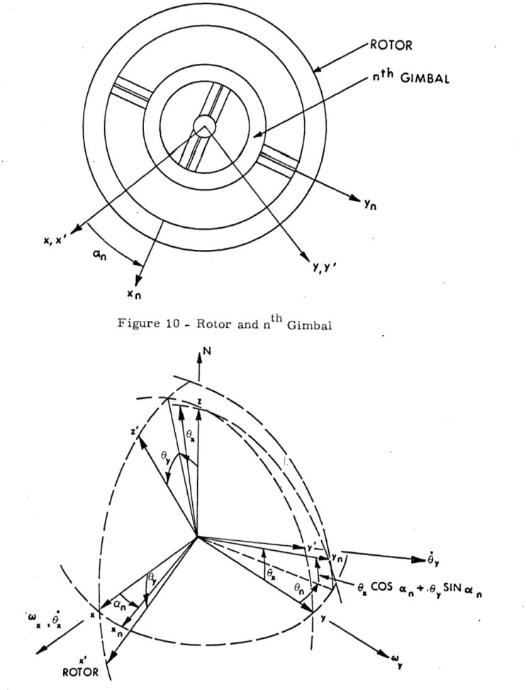
For a more general case of Hooke's Joint Gyro presented in section 4, consider a gyro with n gimbals supporting the rotor (Figure 10). The additional gimbals increase the gyros angular momentum by increasing the mass of the rotating structure. It will be seen in Section 6 that the increased angular momentum is desireable to reduce mass unbalance errors. Also, the extra
gimbals reduce errors due to twice spin frequency angular oscilla-tions of the gyro case about an axis perpendicular to the shaft.
The ideal operating condition for a gyro with n gimbals is to have the rotor remain fixed in inertial space for any type of case motion input. This is the same condition required in the Hooke's Tuned-Joint Gyro.
5. 2 Equations of Motion
The general open loop equation of motion derived below will account for nonsymmetries, damping forces, and torsion element stiffness differences in an n gimbal gyro.
The following four orthogonal reference frames to be defined have origins coincident with the center of torsion established by the rotor to shaft torsion elements (Figure 11).
XYZ - fixed in gyro case
xyz - fixed in the shaft which rotates with respect to the case fixed set with angular velocity N about
the Z axis
28-ROTOR
nth GIMBAL
X, '
Figure 10 - Rotor and nt h Gimbal
N / / / I /'
N
\
.By SIN a n C .w X ROTC .-- Iv
yFigure 11 - Shaft, Rotor and Gimbal Coordinate Sets
29-Xn z - fixed in nth gimbal with xn axis along the
inner torsion element and rotated from the x'y'z' set by On( (1 = 0°) about the z axis
when the rotor is perpendicular to the shaft x'y'z' - fixed in the rotor with the y' axis along the
outer torsion element axes
The equations of motion for the rotor have been derived using Euler's equations of motion for a rigid body.5 A summary of this derivation is given below.
Angular Velocities: Shaft
The angular velocity of the shaft with respect to
inertial space in shaft coordinates is
w = C cos Nt -Y 5(.n Nt
w, = - 5WN + )y COS Nt (5. 1)
Case rotation speeds with respect to inertial space have been assumed negligible compared to the shaft spin speed N. Rotor
The angular velocity of the rotor with respect to
inertial space in rotor coordinates is
w, - 0x + Ox- bNor
An L W A 4 6 4-C Noe (5.2)
WL,= N
-30-where and 8 are angular rotations of the rotor about
x y
the shaft fixed coordinate set. Small angle approximations have been made, i. e. sin = and cos = 1; for most gyros 0 and 0 rarely exceed 0. 5° . The angular velocity terms
x y
along the z component, yWx OxWy, have been neglected since they are small compared to the spin speed N. Gimbal
The angular velocity of the gimbal with respect to inertial space in gimbal coordinates is
TWn
(
cityC
tes
+NS
()of
Wrn -- Wx54si1n + U Cos$ , + N (, GOS°(n 8@.Sn C
The angular velocity terms, Wx sLnO41 ) r<e So50, along the zn axis have been neglected since they are small compared to the spin speed N.
Moments: Gimbal
Applying Euler's equations of motion for a rigid body to the gimbal
-T_.-T. = A._ G. +(.C_ -B_' u).._ u
5. 3)
-Av5 n- - I - 7 n -X' -. vV
(5.
i-n
-Tit -
L Bn - (Cnt - XJ UAIWEwhere Tn and T xn yn are the moments applied to the gimbal by the rotor along the gimbal xn and n axes respectively.
Txs and Tys, the shaft reaction moments exerted on the gimbal
-31-4)
along the same axes, are given by
Tg=X K (sOc 5cX ±G+e c(,) 4- £xnv( C 4.OSc(,i SG.Sw )
(5. 5)
Substituting (5. 5) into (5. 4) yields
Txog = xv< ( 4x cosc -+- G D°x (Coo(,,+-(bD L4| Sit racn,)
AJX 4- (Cn-e$ ) W U vU
(5. 6)
+ 6 COS 0.)
n 9r \ (Cv, uJn )tv v
Rotor:
Applying Euler's equations of motion for a rigid body to the rotor, where TD is a rotor to case rotational damping torque whose vector lies along ',
MX x(Tx Coscq -T,, 5vi cK,) -D,0 =
Ai 4-(-&)Uj uie
Y
-
it
.( ,+T,
5 9
St +
-8 jJ' - Cc-A) x 1 't' Z -A-To = (5. 7)0
where Mxx , Myy are externally applied moments
resolved along the rotor fixed coordinate set.
-32- !
Tr ="~
(-
G, S -
4osc~'5
+
Dyn (- 5 - +B 9 sq 11)-T. = - ~n .5q i +el Co X - D b, - ivt q
M
The case fixed moments applied to the rotor are
M(
-
(M-DR,G')cos
Nt (M-
tQeG)sl
Nt
(5. 8)
-
(MX D-3) S;n
Nt + (My - DR O) cos NtSubstituting equations (5. 1), (5. 2), (5. 3), (5. 4) and (5. 5)
into equation (5.7 ) one obtains
Gx
LA
-
A,%osu
'
+6 Lc
+ Ox [N (C-B) AG-e~l~~N~LV + EN·Z·· ,~~~~~~~~ ~~~~n,~~~ + N,Z
(Cn -)
CO( °f + i,<xn
COS °(, + Z I I Y% I~~~~~~~~~~r s n Z(c, + @, (C-A- B) andG
A.
I
AK 5 Y1 4-G1 jVI · D\ +Ge(c-A)Nt+
- * Z(c'- (C1 - ')5n S ~ +,- (C-A- B) N >Kx <nSin + K < Csto(n7 (5. 10)+
GjlN~
('-
7)S
;
SVI I VI zO (-T j1
= G t) -33-K5%io4.7j~ (5. 9) K <nSl'o n zCr 4T+ (Cr'-IB~,
5' h Z (n + A G X ). I , V\ 2 qIwhere
- G () - A + AcosZ c
+[-N
X(C"-B3+A)
51i X0cONt N +tySiv sn t + y CosN
tKqz (CN -Bu +A,)Co5sq- Nt Sn 1 X CoS N
cos Nt - (M - D Iesi,~ Nt
and
- GyGlt) A, sn ,2 -x > s Co Nt ±+iz C2NA (Cc,-Bw+t P,)is Sn Nt
+ 2, ZA s in 2t p GoS N + ( 51s n lt
-34-Nt
(5. 11) CoS NtA (5. 12) ,x n -.. 4-K4- i AnS
i h+ C-BA)R +F
.N -+ , -+(M -
G" Iit (my
D,-,,e
S~
I~~~XC05N
t +
.
5i
VIt
In these equations, Dn = D
xn
yn
= D, and the x is displaced from the rotor reference x' axisa 1' 2' ct 3 '... an (Figure 12).
Multiplying equation(5. 10)by j =
IA
(5.9) noting the definitionsaxis of each gimbal by angles
and adding to equation
ex
=
ex
-e,
The basic equation of motion for the rotor in rotating shaft
coordinates becomes
I
ex
-+k
n ) +
-
j3
+
CC+155AG,
- j (C-A-B)N~,y
&
nX
+AK+N
tLAI,
(5.1.3)+ Ip xq + 3 p x - GH Ct)
Since case fixed pickoffs and torquers are generally used in these instruments, one needs to determine the motion of the
rotor with respect to case fixed coordinates. Transforming then
the above equation into case fixed coordinates 5 gives
-35-\ e y (
-
ky(S)
(S),
t(S-Zj
N
-
PN
QS-Zj,
S(_{I
-
4.
(s-2zjN)iF, (5, (S-Zj3N) -, S -Zj N) T?( +X js y (S) (S -Z jN) - y (5 - 3N) z (s)where
r\(si
=
Tsli4DtD R cj(AiB-C-2Tl ti ~-nD i ATz =S
(t +j§)s l- as
++
Dj
(T ;
I5)S
K
k
-J
-
NtC
L(5-Ijt
1
5n
+
5n -
Nt
j
+-Cs2LK
N L-j
_jn k-N Z (A+ CB- 4-3
T;
(-.Z)
- (a1- jI)53 - 2j N (LI - j+N-
- jbl cNthS
L
M
-36-(5.14)
II (S) "r, s --2 N) -, T Z Cs - Z N)
+
~(31,
- ,) - (-3 -BTI N
-z-
s
jN(C4
I, - 3i)s
+ 2N(CIT, -T')(-2N'jN)
=
(T
+
jl s -(I+
I
1
R)
-
j
(A1s
+
A)N s
T~lrZ
2AV
L\A-A=
2,-
t.
L..
B + A, cos l l(Kn+ <n
V (<Y ) CSZK
VIA-
+i
TI s= Z(C,-
Be) cos 2Z0( +,(C,'- , I, T, -~~A, -5' z , v R ZI = I (Car By) SVloec2\
-37-, (s-Zsj N)
N
2
iLi
Sn
s20(,
I
- ' : X . ,(Ay,+
B
CZThis equation of motion of the rotor is completely general and describes the performance of an asymmetric gyro in response to any form of angular or torque input. Note that F2(s) and T2(s)
result from nonsymmetries and torsion element stiffness differences
in the gyro.
An operational instrument is constructed as symmetric
as possible and operated at its tuned speed. For a symmetric and tuned gyro, the general open loop equation above reduces to
God (so = ( (s) tYy
+
F~y (s(5.i
15) Neglecting damping effects and operating the instrument at tunedspeed, this equation reduces to
38-As\jsZ +(NC)
(5. 16)
S
(55
Q
(
r)Ms
+
5 My
¢~)
These are the classical equations of motion for a two axis,
symmetrical, free rotor gyro.
Note that for no externally applied moments on the
rotor, the case motion inputs
cdA
and W¥ are equal and oppo-site to the rotor motion with respect to case fixed coordinates.This is the desired relationship for an ideal free gyro.
5. 3 Tuning Condition
The tuning condition necessary for this gyro to operate as an ideal gyro is found using the general open loop equation of motion. For a step angular input to the case, a constant rotor to case angle
is desired for ideal operation considering all other disturbances are
zero. From the general open loop equation this requires that be a constant, or, from equation (5.10)
Patss n,$)L(s-Zj)-rJ 0 (5. 17)
(The second term in the numerator of equation (5. 14) has been neglected in the above expression since it equals zero in the
39-limit as s-0O). The functions F (s) and F2(s-2jN) both have roots equal to zero, therefore, for ~y to be constant in the limit, the denominator must have one root equal to zero or the
characteristic equation must equal zero, that is
LK i ) 3 ( , ,Nu)) - 4(2A+-~C+-1) (5. 18)
- LK-lOd - j
+tautN
c NZJ
+
j S
The value of N that satisfies this equation (neglecting damping) is then the gyro "tuned" speed. It can be shown5 that the value of N which satisfies this equation is
N-
j
1 4(M+ C) (K + ) -1A (5. 19)For a practical design
thus,
the (Angular velocity of spin ncessary for unrestrained
thus, the angular velocity of spin necessary for unrestrained
operation is I/. (5. 20) N = WJ
j
-40-The tuned condition has balanced the negative and positive spring restraints such that the gyro operates as free rotor gyro. This is the same tuning condition derived for the one gimbal Hooke 's Tuned-Joint Gyro.
41-Errors for Multigimbal Elastically Supported Tuned Gyros
Errors for the elastically supported tuned instruments
usually occur from the following sources: (1) mistuning
(2) windage friction forces (3) mass and quadrature unbalance (4) twice spin frequency angular oscillations (5) anisoelasticity (6) and rotor angular offset. The errors produced by these sources
differ for each type of instrument, therefore, one particular instrument
(a Two-Degree-of-Freedom Tuned Gyro with three gimbals),5 will be analyzed to illustrate how the above error terms can be derived. The instrument can be modeled by the general open loop equation (5. 14) for the case of n=3 gimbals.
6. 1 Mistuning
For the Tuned Hooke's Joint Gyro, it is shown (Section 4) that the rotor is unrestrained in space if the positive spring restraint
from the torsion elements cancel the negative spring restraint from
the rotor dynamics. Since the negative spring restraint is a function of the rotor's spin speed, it can balance the positive spring restraint when the rotor is rotated at a specific speed, i. e. the tuned speed.
If the rotor is not rotating at its tuned speed, the torsional and dynamic spring restraints will not cancel, resulting in a net
gyro spring restraint. This restraint will result in a conical
precession of the rotor's spin axis about an inertial space fixed axis.
-42-In the three gimbal, two-degree-of-freedom gyro, a similar balance between torsional and dynamic restraint must exist as in the single
gimbal Hooke's Tuned-Joint Gyro. This unwanted conical precession
resulting from incorrectly setting the rotor speed, i. e. mistuning
the gyro., is called drift.
The precessional period of this drift is somewhat analogous
4
to a conventional two-degree-of-freedom gyro. The precessional
period is
T _z-u-
where the denominator is the gyro net spring restraint and H is the rotor angular momentum.
The inverse of the gyro precessional period times 27r is then the drift rate (D in radians/second) due to the uncancelled spring restraint given by
)= K, - C,N
where
KLI 4 K51)
For H = AN (assuming gimbal inertias are much smaller than
rotor inertias),
-43-AN
1_ __ CN (6.1)
AN A
At the tuned speed, NO, the drift equals zero, thus
K , = Cam
A NO A
or, (6. 2)
Substituting equation (6. 2) into equation (6. 1), the gyro drift is given by
or, normalizing the drift,
D
_C, ore NSN N0
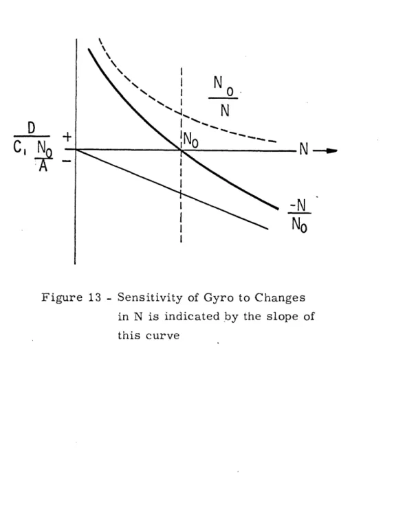
This drift is plotted as a function of spin rate in Figure 13. For
spin rates below NO, the inherent suspension spring rate creates
a positive direction gyro drift (i. e. in a direction expected for a gyro with positive spring restraint). For spin speeds above N0, the anti-spring nature of the dynamic coupling force controls, resulting in a negative gyro drift. At No the two drifts cancel one
another.
-44-D C, I No N I 1%.. ----N N !o
Figure 13 - Sensitivity of Gyro to Changes in N is indicated by the slope of this curve
-45-I
The change in the gyro drift near its tuned condition with spin speed change is the slope of the curve at NO. As C1/A is
decreased, the slope of the curve at NObecomes smaller and thereby the sensitivity of the gyro to changes in its spin speed is reduced. 6. 2 Mass and Quadrature Unbalance Errors
Refer to the coordinate frames defined for the Two-Degree-of-Freedom Gyro with "n" gimbals (Section 5. 2). The coordinates of the center of mass of the nth gimbal are Xgn, Ygn' Zgn' The coordinates of the center of mass of the rotor are xr, Yr' Zr
Assume that the center of rotation of the torsional elements can not be perfectly aligned with gimbal and rotor coordinate frames.
Since mass unbalances in the radial direction (along any direction perpendicular to the shaft) create a zero net torque on the rotor for one rotor revolution, only mass unbalances along the spin axis need to be considered. The torsion element axes are displaced from the rotor and gimbal reference frames only in the z direction by Zxr and zyr (Figure 14).
Mass unbalance torques from shifts of the gimbal and rotor
centers of mass are now derived accounting for misalignments in
the torsion element axes from the reference coordinate sets.
Moments acting on the rotor along the rotor fixed coordinate 5
set due to rotor mass and quadrature unbalance are
TX,= (,-x,,r)- -
M(a
+
%,
T
-(i,-zr')
, + MXr.
+
i.
%
(6.3)
(6.3)
-46-Center of Mass of
Rotor--Center f Mass of the Nth Rotor to Shaft Twist Axis Rotor to Shaft Twist Axis Nth Gimbal to Shaft Twist
Origin of XYZ, xyz
XnYnzn frames of reference
Position of Torsion Twist Axes Figure 14
The source of quadrature unbalance torque is related
to the characteristics of torsion bars when subjected to axial stress from an acceleration field. 6 The quadrature torque is in
the same direction as the acceleration field.
The nth gimbal will cause a torque on the rotor. This torque resolved along the gimbal fixed set is
Tx, = (si I) Xn - M- Yv cae (6.4) The gimbal is restrained from moving about the n axis, therefore no torques can be transmitted to the rotor about this axis, i.e. T = O.
yn
Resolving gimbal accelerations into rotor accelerations
one obtains
0yn
=
-
xs;n
n-
aCos (
,The total moment applied to the rotor will be equal to the sum of rotor mass unbalance torque and gimbal mass unbalance torque,
or
Tx - Txr T A- oscar
(6. 5)
-48-Substituting and combining terms from equations (6.3.) and (6.4) yields Tl
C-
AVx , + p4
7-
-whereajx I
a'=
:z +
a
%
P~~~~~~~P=
M(
-Zxr) ,
;
C"
PF = M (Zgr)- ( tM
VI -
z x,)sin
°(nCOS
'(n
VI (t V xn) Isi n n CoS (ax
rn) 5 C( n xn) 5 i o(v2J
n, n CoS o(Rearranging- the terms in (6.),
Rearranging the terms in equation (6.6),
T= (%+ax,
4
(p+ aL,
FI4.
NTL = Q01L )%+ (F-Ap) "
-i-
-49-(6.6)
(6.7)
where p. PIZ 2 a Ls= QI eQL 2 p U
Combining the torques in equation (6.7 ) and transforming the
torques into case fixed coordinates, equation (6.7 ) becomes
)
where
(pj p N where A = T os Nt -TCsic VNt Ty T sin t + C Nt+ Transformations from rotating frame to case fixed frame(1
~ ~
xr
"·r = axu jyEquation (6.8) represents the torque acting on the rotor due
to mass unbalance in case fixed coordinates. Note, linear accelera-tions at spin frequency, twice spin frequency, and constant mag-nitude cause time invariant torques on the rotor. These unwanted
-
50-(6.8)
torques cause the instrument to drift. For '(y = constant
TXy-= ( S-j LP)a
0
Cx
+ ?
+ jpay -
J
jApFcx
-v Y :-- 0, Y - tpCu i_ ab~_ 7- X-i-Ty
l
-
(tr
-
x+_
)
+
+N(I-VI
+
Z
Note that for no torsion element axis displacement
z 2
(6. 9)
-
- M a
x
+ A
n
,
+
CX
z Cyas one would expect.
How these unwanted torques affect the drift of the instru-ment can be seen by substituting into the classical equations of motion, equation (5. 16), for a two axis, symmetric free rotor gyro.
-51-Tx + 3 Ty
TM te2- ~ )
if tsz 2 A (9C)1 (. l
(6. 10)
For constant values of torque Tx and Ty
(6. 11)
N C
To decrease these drift rates the Z axis inertia and
spin speed must be increased as one would expect. Note here the two-degree-of-freedom instrument could be considered as two uncoupled single-degree-of-freedom instruments.
For ay = twice spin frequency
Errors produced by twice spin frequency accelerations along an axis perpendicular to the spin axis are found by substituting
ag
a
Si (YNt;,Y)
52-into the general torque equation (6.8). invariant torque becomes
or substituting for Aq and P
-Tx:.I1A
(war -,r) ((x - SI) 4which reduces to
(6. 13)
~-·, ed4
for no torsion element axes displacement or quadrature unbalance.
Note only gimbal pendulosities contribute to the torque. Separating equation (6.13) W, tZV CoS zc<,) 4 K~~~ + (a t4 9 5tv 2" r) t yo 4 ( nn (6. 14)
-( "' 13y,
Z~
ty
TY
Y~~
=(a
L/VL <4 En Sun inr
)iW
,
-53-(6. 12)
The constant time
+ M,(: n O'xTo
(-I,
It is seen that the torques on the rotor are coupled for acceleration inputs at twice spin frequency.
For a:v = spin frequency
Errors produced by vibrations at spin frequency along the
shaft axis are found by substituting
a1
-- a,1 Str (N% + )into the general torque equation (6.8)
substituting for p
and
pb-
_X
_
[
rtao
4 n e (6. 15) Again, as in the twice spin frequency acceleration input, thetorques are coupled.
6. 3 Twice Spin Frequency Angular Oscillations of the Case A. steady state drift of the rotor with respect to the case can exist when the case is oscillated at twice spin frequency about an axis perpendicular to the shaft.
5
To derive an expression for this drift rate, consider case
motion inputs of the following
py (c)' - 4 bin t + AS )A eI
54-where
P
and X are arbitrary phase angles in space and time domain respectively.Multiplying the Y-input by j- I , combining the inputs, and substituting into the gyro's general open loop equation of motion (5.14), the gyro's drift becomes
-6y~s B =-&0>y ) SI,(s) _ (6. 16)
ncs) taLs) where A(= F;(s)Y, (s- N) -)s- Fz 2N) s) AoSa +A s-t+ ' + A _t,s + A
s)
=
z (,s)F
-
, ((
N2j-(s)z
(s2
CS)
-A + A .S. +c s CApplying the final value theorem to this expression, the steady
state drift becomes
s -LIM , '$(5) o A s) s+o 1 y
Y
Z3 st3C sZ> 5)) A2js) (6. 17)6The first term of this expression vanishes as S -_ O
The second term expanded becomes
-55-*
0
{ D=-L~ So e W cos Y +(s zj s Ps5-90
(5
_tj
-j (S
-2j
N + IJw)
x
_b_+_b___ _ B_ s + Bb (6.18) wherec [ SK-
%+
(D
n
~j
&J))
15 i (TD+nN
) -+(2A+B-2C
+J
If the instrument is operated at tuned speed the Ac term will vanish provided damping is neglected (i. e. TD + nND = 0)
and K = N2J.
When the gyro is oscillated about an axis perpendicular
to the shaft at twice spin frequency (i. e. w = 2N ), equation (6. 18) reduces to
Uk
¢~ (6. 19) Assuming that, JA+B+ A+~+e.-56-then
(6. 20)
N =-
Ne
0;K-Ke K
(Ay+ B,- C
) e
m
t~
.
L(K.W-Kv%
(A,,B
,
C,)
Notice that angularly spacing three gimbals equally (i. e. n=l at 00°, n=2 at 120°, n=3 at 2400) about the spin axis, reduces the term inbrackets to zero and therefore reduces the drift to zero. A. three
gimballed gyro has its three gimbals angularly displaced in this manner. The error sensitivity to twice spin frequency angular
inputs can be reduced by making the ratio Fm/NO as large as possible.
This error term would be difficult to test for since table
oscillations would have to be around 200 cps. This alone might
justify not considering this error term in more detail for this thesis.
6. 4 Damping forces due to windage
When the rotor is rotating in a fixed plane and the driving shaft is misaligned by some small angle o( , the gimbals will
oscillate about its torsion bar hinges + o( in one revolution relative
to the rotating shaft (Figure ). This motion introduces a damping torque from the windage forces which precesses the gyro about the axis of misalignment in a direction to reduce the
misalign-ment to zero.
-57-Consider a gyro where rotor inertias are much larger than gimbal inertias (which is a good approximation for this
instrument) and differences in inertias of the rotor about x' and y'
axes and differences in torsion bar stiffnesses are negligible. The
characteristic equation for the gyro becomes5
r,
s) (-2N ) (6. 21)where
IVs-, -.I + '- -
j(z-
+-j
DR D( N D o
D)- E L
T
Lo)&
)
Notice from the gyros characteristic equation that the gyros time constant is reduced by adding the damping term DR/I. For the gyro to operate ideally, the closed loop response time must be faster than the gyro's response to the damping force. The damping forces are then undesireable. If the closed loop null torquing response is much faster than the rot or response to
58-the damping force, 58-the windage forces can be completely neglected.
For a three gimballed instrument this will be true.
6. 5 Rotor Offset Angle
Drift rates can occur when the rotor spin axis is offset from the shaft Z axis. This offset angle is produced by a pick-off null shift, when operating the gyro in a torque to balance mode, or an angular tilt of the gyro case with respect to the rotor, if the gyro is operated in an open loop mode.
The errors that are produced by the rotor offset angle can be derived from the gyro's general open loop equation (5.14).
Assuming gimbal inertias are much smaller than rotor
inertias, the general equation of motion reduces to
Ixy (5) -_ () (S) (6. 22)
Substituting for T'Is() FC(s), and assuming a step input in y (m = y ( ) the solution in the time domain is5
-_x ~ V, (6. 23)
59-where
_ uD
z (a"+
Ln
For the input
+
-4Q(O)
rotor deflections with respect to case fixed coordinates become
IG (i) --
-
tr
cos i tcC)e
'S
i% trFn, F
(6. 24)
By
()
- (oYC
) e/
F -C
F,,
Expressions for the error rates due to rotor angular offsets are obtained by evaluation of the differentials of the above equations.
-
' y ) SN eF (6. 25)-
c () SN OFM - 60-the _C (O)7
P.,These drift rates can be reduced by minimizing the rotor offsets (o) and y Co) ) damping, and operating the gyro
at a spin speed corresponding to its tuned speed. 6. 6 Anisoelasticity
In this family of instruments, the anisoelastic effect is a function of mismatch between translational stiffness of the rotor to shaft suspension along the spin axis and along an axis perpendicular to the spin axis.
For a non symmetric rotor to shaft suspension, the aniso-elastic coefficient is given by5 (assuming rotor mass >> gimbal mass)
h~z ( % if) 4 V
2
2J (6. 26)(moment per unit acceleration 2) where
M = z
For the radially symmetric gyro, equation (6.26) reduces to
mQt pr
uni_)
(6.
27)
(moment per unit acceleration )
-61-Error Model for a Two-Degree-of-Freedom Tuned Gyro One philosophy of inertial gyro testing is that the test program should provide accurate measurement of the coefficients
of a modeling equation which mathematically defines the gyro per-formance in any environment.
This model should contain the errors which have been
measured over a wide range of environments for a given gyro family. Requirements for a particular application are then included in the
test and evaluation program to extend the model to more accurately
describe its performance for that particular application. A. "complete"
model of the gyro is finally obtained which describes the gyro's performance in a given environment without having to test in that particular environment ("complete" is enclosed in quotation marks
since an adequate model for today's applications will not necessarily be adequate for future applications).
To derive an error model for the family of two-degree-of-freedom elastically supported tuned gyros consider the type of
previously derived error terms in Section 6. The error terms can
be divided into terms independent of an acceleration field (mistuning, windage friction forces, rotor offset angle), proportional to an
acceleration field (mass and quadrature unbalance), and proportional to an acceleration field squared (anisoelasticity).
The general torque equation about the Y axis is divided into these three torque categories as follows
62-MY = Y M 8\o y May (7. 1)
where
MIy = acceleration insensitive torques about the Y axis May = acceleration sensitive torque about the Y axis
Ma2Y = acceleration squared sensitive torques about the Y axis In spite of the differences in this gyro from the
single-degree-of-freedom gyro,. the gyro is found to be susceptible to the same type
of errors when subject to translational accelerations.
The acceleration sensitive torques can be represented from
equation (6.8 ) as
Day 'C q$y VpyraX K (7.2)
where
- er a r) + xn
The acceleration squared sensitive torques occur from
compliance effects. The compliance coefficients are defined as follows:
IR t= displacement along spin axis due to a unit force along Z
K(y = displacement along spin axis due to a unit
force along Y -
63-The displacement of the rotor center of mass due to the com-pliance of the support structure along the Z axis is then
d
=
Kii ~(5)2 + gay m(S&)y + RX <(S)X
(7' 3)(7.3)where
= effective displaced mass [Sf)x (s)y (s$) = specific force with respect to
inertial space along X, Y, Z axes
respectively
The displacement of the center of mass along the x axis will not contribute to a steady state torque about Y for a constant aZ input since the whole support structure is rotating about the Z axis (i. e., in one revolution of the rotor, the resultant torque on the rotor due to aZ would equal zero. )
This displaced mass creates a torque on the rotor in an acceleration field aX of
May = (S,''m
(s
m(S)y 4ix m
(sx
or
e¥
__ l
a
&
la,
+ KyacOy
Ck + KxZ
(7.4)
64-where
t
=,
etc.
K,, - - kx
(Sf)¥ = -o.¥
The total torque about the Y axis is the sum of the
acceleration insensitive torque M YJ the mass unbalance torque May, and the compliance torques Ma2y. therefore,
yM i o-Y + Kpy 0-T a: +iam a,, + Kjy Axay +K (7.5) Equation (7. ) characterizes the error torques about the
gyro's Y axis on the basis of linear theory.
With a similar analysis to the above, the X axis torque equation becomes
Mi
h
+
Ka + x
ay -.
Kay-yo
-
(7.6)
where
qz, = accelerv--iom insensit+ve orque along X asis
z
KVI frY. VI
-65-These error models take into account only errors terms that have been analyzed thus far in this thesis. It is likely that more error sources will become evident as the gyro is tested. In
2
particular, error terms proportional to aZ, aZ , ayaZ (for the
Y torque equation), and aaZ (for the X torque equation) might become apparent.
66-Test Procedure for a Two-Degree-lof-Freedom Tuned Gyro
A. general format for gyro testing should include the
following: 13
(1) 'Verification of assembly procedures (commonly called acceptance tests)
(2) Verification of design parameters (commonly called
qualification or engineering evaluation tests)
(3) Development of the gyro error model equation (4) Development of advanced test techniques
(5) Indication of the need for development of advanced
test equipment
(6) Determination of the reasons for failure to perform
as expected (commonly called diagnostic tests)
It was noted in Section 6 that for constant g inputs the two-degree-of-freedom instrument could be considered as two uncoupled
single-degree-of-freedom gyros (for oscillatory linear and angular
inputs, the instrument cannot be considered as two uncoupled single-degree-of-freedom gyros). The two-single-degree-of-freedom gyro can therefore be subject to all the tests for a single-degree-of-freedom gyro in the one g environment. By amplifying the output axis of the X axis pickoff, the instrument is reducd to a
single-degree-of-freedom gyro, having the X axis as electrical input axis while the Y axis serves as pickoff output axis and mechanical input axis. The
-