Publisher’s version / Version de l'éditeur:
International Journal of Adhesion and Adhesives, 2018-03-20
READ THESE TERMS AND CONDITIONS CAREFULLY BEFORE USING THIS WEBSITE.
https://nrc-publications.canada.ca/eng/copyright
Vous avez des questions? Nous pouvons vous aider. Pour communiquer directement avec un auteur, consultez la
première page de la revue dans laquelle son article a été publié afin de trouver ses coordonnées. Si vous n’arrivez pas à les repérer, communiquez avec nous à PublicationsArchive-ArchivesPublications@nrc-cnrc.gc.ca.
Questions? Contact the NRC Publications Archive team at
PublicationsArchive-ArchivesPublications@nrc-cnrc.gc.ca. If you wish to email the authors directly, please see the first page of the publication for their contact information.
NRC Publications Archive
Archives des publications du CNRC
This publication could be one of several versions: author’s original, accepted manuscript or the publisher’s version. / La version de cette publication peut être l’une des suivantes : la version prépublication de l’auteur, la version acceptée du manuscrit ou la version de l’éditeur.
For the publisher’s version, please access the DOI link below./ Pour consulter la version de l’éditeur, utilisez le lien DOI ci-dessous.
https://doi.org/10.1016/j.ijadhadh.2018.03.008
Access and use of this website and the material on it are subject to the Terms and Conditions set forth at
Nanoreinforced epoxy and adhesive joints incorporating boron nitride nanotubes
Jakubinek, Michael B.; Ashrafi, Behnam; Martinez-Rubi, Yadienka; Rahmat, Meysam; Yourdkhani, Mostafa; Kim, Keun Su; Laqua, Kurtis; Yousefpour, Ali; Simard, Benoit
https://publications-cnrc.canada.ca/fra/droits
L’accès à ce site Web et l’utilisation de son contenu sont assujettis aux conditions présentées dans le site LISEZ CES CONDITIONS ATTENTIVEMENT AVANT D’UTILISER CE SITE WEB.
NRC Publications Record / Notice d'Archives des publications de CNRC:
https://nrc-publications.canada.ca/eng/view/object/?id=69205358-f52c-4012-97c3-6d0630a8bc60 https://publications-cnrc.canada.ca/fra/voir/objet/?id=69205358-f52c-4012-97c3-6d0630a8bc60
Author’s Accepted Manuscript
Nanoreinforced
epoxy
and
adhesive
joints
incorporating boron nitride nanotubes
Michael B. Jakubinek, Behnam Ashrafi, Yadienka
Martinez-Rubi,
Meysam
Rahmat,
Mostafa
Yourdkhani, Keun Su Kim, Kurtis Laqua, Ali
Yousefpour, Benoit Simard
PII:
S0143-7496(18)30086-1
DOI:
https://doi.org/10.1016/j.ijadhadh.2018.03.008
Reference:
JAAD2170
To appear in:
International Journal of Adhesion and Adhesives
Accepted date: 2 March 2018
Cite this article as: Michael B. Jakubinek, Behnam Ashrafi, Yadienka
Martinez-Rubi, Meysam Rahmat, Mostafa Yourdkhani, Keun Su Kim, Kurtis Laqua, Ali
Yousefpour and Benoit Simard, Nanoreinforced epoxy and adhesive joints
incorporating boron nitride nanotubes,
International Journal of Adhesion and
Adhesives,
https://doi.org/10.1016/j.ijadhadh.2018.03.008
This is a PDF file of an unedited manuscript that has been accepted for
publication. As a service to our customers we are providing this early version of
the manuscript. The manuscript will undergo copyediting, typesetting, and
review of the resulting galley proof before it is published in its final citable form.
Please note that during the production process errors may be discovered which
could affect the content, and all legal disclaimers that apply to the journal pertain.
Nanoreinforced epoxy and adhesive joints incorporating
boron nitride nanotubes
Michael B. Jakubineka*, Behnam Ashrafib, Yadienka Martinez-Rubia, Meysam Rahmatc, Mostafa Yourdkhanid†, Keun Su Kima, Kurtis Laquab, Ali Yousefpourb, and Benoit Simarda*
a
Division of Emerging Technologies, National Research Council Canada, 100 Sussex Drive, Ottawa, ON K1A 0R6, Canada
b
Aerospace, National Research Council Canada, 5145 Decelles Ave., Montreal, QC H3T 2B2, Canada
c
Aerospace, National Research Council Canada, 1200 Montreal Road, Ottawa, ON K1A 0R6, Canada
d
Department of Mechanical Engineering, McGill University, 817 rue Sherbrooke Ouest, Montreal, QC H3A 0C3, Canada
Abstract
Boron nitride nanotubes (BNNTs) offer complimentary properties to carbon nanotubes (CNTs) and interact more favorably with epoxies than do CNTs. This could make BNNTs the preferred nanotube for reinforcing epoxy when electrical conductivity is not required, and particularly where features such as transparency/color, neutron absorption or electrical insulation are advantageous. Here we report epoxy nanocomposites containing 1 to 7 wt% raw BNNTs. The elastic modulus and fracture toughness increased progressively with loading up to 5 wt% BNNTs. Adhesive joints (ASTM D1002) indicated average improvements of ~10% in joint strength at 2 wt% raw BNNTs, but substantially reduced strength for a 5 wt% BNNT adhesive joint. Observation of the failure surfaces suggests that BNNTs impede crack propagation leading to increased joint performance despite a mixed-mode failure with a substantial contribution from adhesive failure. BNNTs purified by removing the elemental boron impurity were more effective, yielding 15% joint strength improvements at 1 wt% loading. This nanocomposite is also semi-transparent, showing the potential for reinforced, electrically insulating, transparent adhesives based on BNNTs.
* Corresponding Authors. Email: Michael.Jakubinek@nrc-cnrc.gc.ca, Address: 100 Sussex Drive, Ottawa, ON K1A 0R6, Canada; Tel.: +1 6139904250 (M.B. Jakubinek); Email: Benoit.Simard@nrc-cnrc.gc.ca, Tel.: +1 6139900977 (B. Simard)
Urbana-Keywords: Nanocomposites, Mechanical properties, Adhesion, joints/joining
1. Introduction
The ability of carbon nanotubes (CNTs) to reinforce mechanical properties of polymers is well-established. In many cases the tensile properties are incrementally but significantly improved relative to the polymer matrix by the addition of < 1 wt% to a few wt% CNTs. However, while there is much study of CNTs in adhesive-relevant polymers, the properties of the composites do not directly predict the bond strength of an adhesive joint and there is a much smaller body of literature in this area. More recently, nanomodified adhesives were reviewed by Shadlou et al. [1], who summarized literature results for a variety of nanofillers (CNTs and other carbon nanoparticles, metal nanoparticles, nanoclays and nanosilica) on stiffness, fracture toughness, peel strength and shear strength of adhesives and identified the primary mechanism in improved adhesive strength is increased fracture toughness associated with deviating a crack or by crack bridging. Improvements in joint strength of 10-50% have been reported for CNT-filled adhesives, mostly in lap shear tests [2-12]. Addition of CNTs also imparts functional properties, in particular electrical conductivity, and the composites can be used as conductive adhesives [2,8] and for heating [13] or structural health monitoring of adhesive joints [5]. However, in some cases the electrical or optical properties obtained following CNT integration can be undesirable, such as where electrical isolation is required or where it is desirable to have a transparent or colorable adhesive or coating.
In this work we evaluate the use of boron nitride nanotubes (BNNTs), a mechanically and geometrically similar reinforcing material to CNTs that offers differing functional properties [14]. As a result of contrasting electronic structure to CNTs, BNNTs are all wide-band-gap insulators and absorb in the UV but not in the visible spectrum. These features differ in comparison to CNTs and will enable optically transparent, nanoreinforced adhesives with maintained (or increased) the
electrical resistivity and breakdown strength. However, as reviewed by Kim et al. [15], BNNT synthesis only recently advanced to the point where sufficient quantities of material are available to produce bulk composites and composite structures. BNNT-polymer composites have been studied for neutron shielding [16], UV absorption [17] and, in recent report from Takizawa et al. [18], for thermal conductivity enhancement in a glass-fiber laminate structure.
As a reinforcement for polymers, BNNTs offer similar mechanical reinforcement potential to CNTs and have been reported to increase strength and stiffness of polymers [14]. Using as-synthesized BNNTs, increased Young’s modulus is the most common report (e.g., +5-15% at 1 wt% BNNTs in PS [19], PVA [20] and PC [21]). Larger improvements in modulus (e.g., 20-50% for 1-3 wt% BNNTs) are reported with functionalized BNNTs and such cases more commonly show improved tensile strength as well [14,20,21]. Theoretical studies by Nasrabadi et al. [22] suggest that BNNTs will have greater affinity for polymers, and Chen et al. [23] have measured both higher interfacial strength and higher interfacial energy for BNNT-epoxy and BNNT-PMMA interfaces than for similar CNT cases. This indicates higher resistance to nanotube pull-out, and hence suggests that BNNTs may be more favorable than CNTs in terms of enhancing the fracture toughness and bond strength of epoxy adhesives. In addition, Nigues et al. [24] determined that inter-wall friction in BNNTs is much higher than for CNTs, which could make multi-walled BNNTs a more efficient filler than multi-walled CNTs. Based on this strong potential, we have investigated BNNT-enhanced adhesives complimentary to those reported with CNTs. Here we report the integration of 1 to 7 wt% BNNTs into and epoxy adhesive (Epon 828/Epikure 3223) by a simple, solvent-free planetary mixing process. The effect of BNNTs on the viscosity, transparency, tensile properties and fracture toughness of the epoxy resin is presented, along with the first report on the joint strength, using a single lap shear test, for a BNNT-modified epoxy adhesive.
2. Materials and methods 2.1. Materials
Epon 828 and Epikure 3223 were obtained from Miller-Stephenson Chemical Company. The BNNTs were few-walled, small-diameter (~5 nm) BNNTs produced from hexagonal boron nitride (hBN, MK-hBN-N70 from MK Impex Corp) using an RF plasma torch method as previously reported by Kim et al. [25]. The as-synthesized material was homogenized by mechanical grinding and dried at 120 °C prior to mixing into composites. This homogenized, fluff-like form, which is referred to as r-BNNT in this work, is also available commercially as BNNT-R from Tekna Advanced Materials (Sherbrooke, Canada) and through Sigma Aldrich (Aldrich Product No. 802824). The purity of the as-synthesized material is estimated to be over 50% BNNTs, with impurities including elemental boron and hBN derivatives. The boron impurity can be removed by chemical processes and the hBN-like component minimized by washing and filtration steps. No metal catalyst is required in the process and hence metal impurities are avoided. In this work, the BNNTs were also used in a partially purified form (p-BNNTs) where the elemental boron impurity had been removed, as verified by X-ray photoelectron spectroscopy (see Figure S1), but there was no extensive effort to reduce the quantity of hBN-like impurities.
BNNT-epoxy nanocomposites were prepared by solvent-free, planetary mixing (Thinky ARE 310) into the epoxy resin (Epon 828). BNNTs were mixed with three, two-minute intervals of mixing (2000 rpm), allowing the resin to cool between the mixing intervals. The baseline and nanocomposite samples were cured by addition of Epikure 3223 hardener (12 parts per hundred parts epoxy resin). The samples were debulked in vacuum for 10 minutes prior to preparation of films or bulk samples, or fabrication of joint panels. In all cases, the epoxy was cured at room temperature for a minimum of 24 hours, followed by a 2 hour post-cure at 120 °C.
2.3. Nanocomposite Characterization
Viscosity and gel time of the baseline and nanocomposite epoxies were measured using a TA instruments AR2000 Rheometer with an Environmental Test Chamber accessory.
Sample uniformity was assessed by eye and transmission optical microscopy. Optical microscopy samples were prepared by compressing a drop of the composite adhesive between a microscope slide and a glass cover slip. A filter membrane was used as a gasket to ensure samples were of comparable thickness. Fracture surfaces of specimens employed in destructive tests also were imaged by optical microscopy and scanning electron microscopy (SEM; Hitachi S4700).
For tensile properties characterization, 200 μm thick films were prepared by curing the composites between two glass plates treated with a release agent. Metal shims were used to control the film thickness and dog bone shape test coupons made according to ISO 527-2 were punched using a die punch (Type 1BB). These coupons were tested in tension until failure on a micro-tensile test frame (Fullam Substage Test Frame) to determine the elastic modulus, ultimate tensile strength and ultimate tensile strain. At least five coupons of each material were tested using a displacement rate of 0.5 mm/min. Film samples were also assessed by dynamic mechanical analysis (TA Instruments Q800) using a tension fixture in force control mode with a 1 Hz oscillating displacement of magnitude 15 μm. Temperature was swept from room temperature to 300°C at a ramp rate of 2°C/min. Finally, thicker dog-bone samples (per ASTM D 0638 Type IV) were prepared by molding and tested on a servo-hydraulic load frame from MTS Systems Corporation to verify selected results (baseline adhesive and 2 wt% BNNT nanocomposites).
Fracture toughness characterization was performed on single edge notched bending (SENB) specimens according to ASTM D 5045. Specimens with dimensions of 2 mm × 4 mm × 20 mm
were prepared by casting the resin in a custom designed Teflon mold. A notch with a length of 1.9 mm was created in the middle of each specimen using a precision diamond saw, and the tip of the notch was sharpened using a razor blade. The overall notch length was ~ 2 mm. Specimens were tested in a three-point bending test geometry with a span of 16 mm using the micro-tensile test frame. Load was applied at a crosshead speed of 0.05 mm/min until the specimens fractured. At least five specimens were tested for these experiments, and the average value for each formulation is reported.
2.4. Joint Preparation and Testing
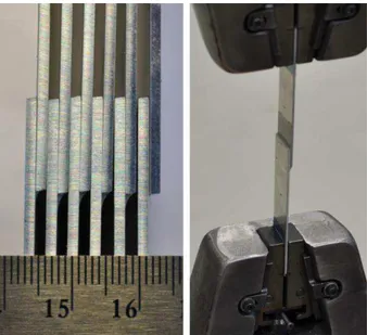
Adhesive joints were prepared using neat and BNNT-reinforced Epon 828 containing 0 to 5 wt% BNNTs (Figure 1). A single lap shear configuration was selected and joint panels were prepared and tested according to ASTM D1002 due to the relatively simple test method and smaller quantity of adhesive required. Briefly, 20.3 cm wide aluminum adherends were prepared by grit blasting and sol-gel treatment. Following addition of the Epikure 3223 hardener to the nanocomposite resin by planetary mixing, the adhesive was degassed and spread across the bondline. Piano wires (250 μm) were employed as spacers and the joint was completed by adding the second adherend and curing under compression at room temperature followed by a post-cure step at 120 °C for 2 hours prior to cutting and testing. All panels were cut into 6 coupons each for testing. Joints with the baseline adhesive (0 wt% BNNTs) were prepared in parallel with the BNNT-modified adhesive as a control sample.
Figure 1: Five ASTM D1002 single lap shear joint coupons cut from a joint panel (left), and lap shear test (right). (Color online)
3. Results and discussion
3.1. Bulk material characterization
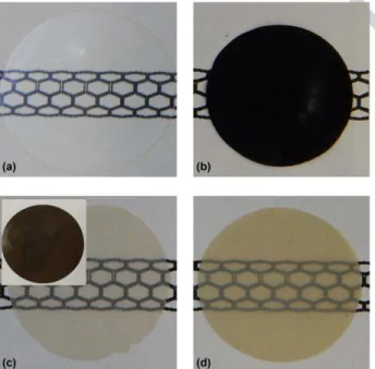
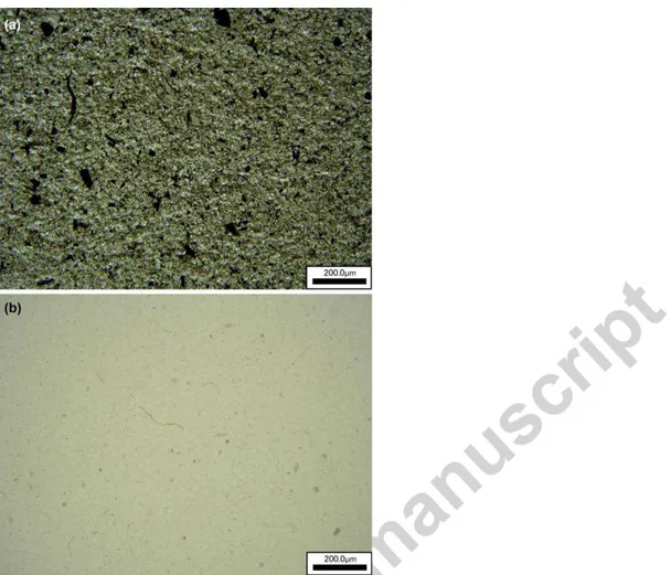
Photographs on neat and nanomodified resin are shown in Figure 2. In contrast to the case for CNTs, an epoxy adhesive containing BNNTs can be semi-transparent. Good transparency is obtained by using p-BNNTs without a significant amorphous boron impurity (Figure 2b and 2c), which leads to a darker brown color and lower transparency for composites produced using r-BNNTs (Figure 2c, inset). Although the integration achieved in this simple method is not sufficient to produce thick transparent composites, the result already illustrates sufficient integration quality to employ BNNTs in transparent adhesive films with a comparable thickness to that of the actual adhesive bondline. Transmission optical images of thin (10-20 μm) films provide an indication of the uniformity of the nanotube dispersion for CNT samples (Figure 3a), where the high absorption of visible light by CNTs is the source of contrast. Corresponding BNNT-epoxy films (Figure 3b) show only minimal contrast, most of which is also observed for neat epoxy indicating it is due to challenges associated with thin film preparation (e.g., cleanliness, microbubbles) rather than due to
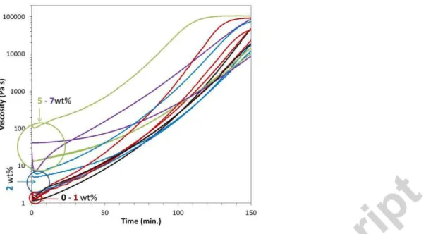
the BNNTs. Nanotubes are clearly observed in SEM micrographs (Figure 4), where fracture surfaces show the presence of many nanotubes with sizes consistent with the diameter of the individual BNNTs (~ 5 nm) or small bundles and are distributed reasonably well rather than appearing to be concentrated into large clumps. Addition of BNNTs increased viscosity of the resin (see Figure 5 and Figure S2); however, repeated measurements at 1 wt% (4 measurements) indicate that at this loading the nanocomposite, at 1.4±0.1 Pa s, remains comparable in viscosity to the neat epoxy (0.6±0.4 Pa s). At 2 wt%, both the viscosity and gel time are still within a practical range for preparing cured composite samples and adhesive joints, although greater variability was observed for repeated measurements. Viscosity increases roughly an additional order of magnitude between 2 wt% and the higher loading samples (5 – 7 wt%) and shows high variability, which may be indicating inhomogeneous mixing when larger quantities of BNNTs are incorporated (i.e., inconsistent BNNT content in the small aliquots removed for rheological characterization).
Figure 2.Photographs of (a) neat and (b-d) nanotube-modified epoxy films placed on top of an illustration of a nanotube structure. 1 wt% p-BNNT-epoxy composite films of (c) 250 μm and (d) 450 μm thickness provide good transparency while a thin (125 μm) CNT-epoxy film, (b), is opaque. The inset to (c) shows an equivalent composite with r-BNNTs where transparency is much lower and the background image is barely noticeable. (Color online)
Figure 3. Transmission optical microscopy images of nanotube-epoxy thin films: (a) CNT-epoxy shows strong light absorption; (b) p-BNNT-epoxy shows minimal contrast.
Figure 5. Evolution of viscosity during gelation at room temperature for Epon 828/Epikure 3223 (black; ──) and related nanocomposites with 1 wt% (red; ──), 2 wt% (blue; ──), 5 wt% (green; ──) and 7 wt% (purple; ──) BNNTs. Repeated measurements are indicated by additional lines of the same color. The G’ and G’’ curves are available as Figure S2. (Color online).
The tensile properties determined from thin film samples show a consistent increase in the elastic modulus with the addition of up to 5 wt% BNNTs (Figure 6 and Figure S3, online supporting information). There was no additional increase at 7 wt% and, at that loading, the tensile strength also dropped relative to the lower BNNT content composites. The trend obtained for elastic modulus and strength from the thin film characterization was verified using baseline and 2 wt% r-BNNT-epoxy samples molded to form larger dog bones (ASTM D 0638 Type IV), which are less susceptible to edge defects. These samples yield slightly higher strength and modulus for both the epoxy (σ = 62 ± 6 MPa, E = 2.29 ± 0.07 GPa) and 2wt% nanocomposite (σ = 64 ± 1, E= 2.66 ± 0.06 GPa), but verify the increased stiffness and maintained strength following the addition of BNNTs. These dogbone specimens showed an average increase of 16% in the elastic modulus with the incorporation of 2wt% BNNTs and minimal increase, within the uncertainty limits, in tensile strength. Failure strain decreased with addition of BNNTs (from ~6% for the neat epoxy to ~4%
failure strain for 1-2 wt% BNNTs) and drops further for the highest BNNT loadings (5-7 wt%: ~2.5% failure strain) (Figure S1).
Figure 6: Elastic modulus and ultimate tensile strength of nanocomposite films of Epon 828/Epikure 3223 containing 0 to 7 wt% r-BNNTs (error bars correspond to one standard deviation). The raw data, expressed as stress-strain curves to account for small differences in cross-sectional area, are available as Figure S3 online.
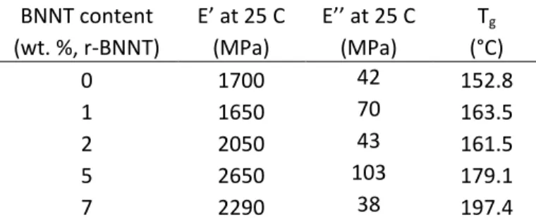
Consistent with the elastic modulus measurements, dynamic mechanical analysis (DMA) showed that the storage modulus also increased with BNNT addition up to 5 wt% (Table 1). There was no consistent trend in the loss modulus data; however, the baseline epoxy and nanocomposites up to at least 2 wt% BNNTs exhibited qualitatively similar behavior for both E’ and E” (see DMA traces: Figure S4, online). The increased glass transition temperature (Tg), which was determined from the peak in tanδ (Figure S4, bottom), is consistent with a strong filler-matrix interaction hindering the mobility of polymer chains, as described by Wang et al. [26] for BN nanosheets in PMMA and by Morales-Cruz et al. [27] for BNNTs with epoxy. The increase here is quite dramatic; however, further study would be required to explain this observation. Notably, a 1 wt% sample using p-BNNTs, which was evaluated in the joint tests described below, had only a slightly
increased Tg (155 °C); therefore, it is not clear if the increased Tg is attributable to the BNNTs or to other factors such as boron nanoparticle impurities in the r-BNNT material.
Table 1. Dynamic mechanical analysis results for storage modulus (E’) and loss modulus (E’’) for BNNT-reinforced Epon 828/Epikure 3223 composites.Tg was estimated from the peak in the tan(δ) signal in dynamic mechanical analysis tests. The corresponding DMA traces are available as Figure S4.
BNNT content E’ at 25 C E’’ at 25 C Tg
(wt. %, r-BNNT) (MPa) (MPa) (°C) 0 1700 42 152.8 1 1650 70 163.5 2 2050 43 161.5 5 2650 103 179.1 7 2290 38 197.4
While ultimate strain in the tensile tests progressively decreased with BNNT addition, as can be seen in the stress-strain data (Figure S3), single-edge notched bending tests show that fracture toughness increased with BNNT addition (Figure 7). As with the elastic and storage moduli, fracture toughness approached a maximum around 5 wt% BNNTs. The fracture surfaces of the nanocomposites (Figure S5) reveal increased roughness, particularly for the largest BNNT contents (5 wt% and 7 wt%), indicating that the BNNTs play a role in inhibiting fracture and increase the energy dissipation as the crack grows.
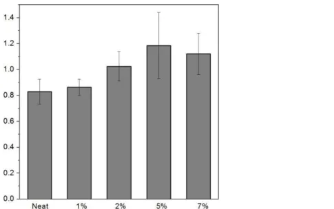
Figure 7. Fracture toughness of Epon 828/Epikure 3223 and related composites with up to 7wt% r-BNNTs (error bars correspond to one standard deviation).
3.2. Adhesive joint characterization
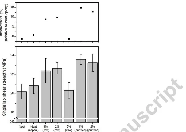
Based on the tensile and fracture toughness test results, loadings of 0, 1, 2 and 5 wt% BNNTs were selected for evaluation as adhesives in single lap shear tests. The macroscopic failure mode for BNNT composite adhesives was mainly adhesive failure at the interface of the epoxy and the adherends, as seen from optical observation of the failure surfaces (Figure 8). This observation demonstrates that the strength of the epoxy is higher than the bond strength between the epoxy and the aluminum adherends. Notwithstanding, the single lap shear strength still increased with BNNT addition up to 2wt% (Figure 9) indicating that the addition of nanotubes improved not just the properties of the epoxy but also the strength of the epoxy-aluminum interface. With a further increase in loading, to 5 wt%, strength dropped and was equivalent to neat Epon 828 adhesive. The lower optimum concentration of BNNTs in comparison to the fracture toughness and modulus may relate to greater difficulty preparing high quality joints with the higher BNNT contents due to higher viscosity. At 5 wt% BNNTs the viscosity is 1 to 2 orders of magnitude higher than the neat epoxy, which affects the mixing and degassing of the composites and also makes it more difficult to spread
the adhesive uniformly during joint preparation. One approach to address this issue is to use purified BNNTs. An initial test of this approach was performed using 1 wt% and 2 wt% p-BNNTs, where on a per-weight basis the amount of nanofiller added contains a larger amount of BNNTs due to removal of the elemental boron impurity in r-BNNTs. In this case, the 1 wt% purified BNNT composite yielded an increase in joint performance of 15% relative to the baseline epoxy but no additional improvement from 1 wt% to 2 wt% p-BNNTs. The single-lap-shear samples produced with these p-BNNT-epoxy composites displayed the best joint performance in the present study (Figure 9), indicating that removal of the boron impurity is useful not just to improve transparency but also to maximize the joint strength.
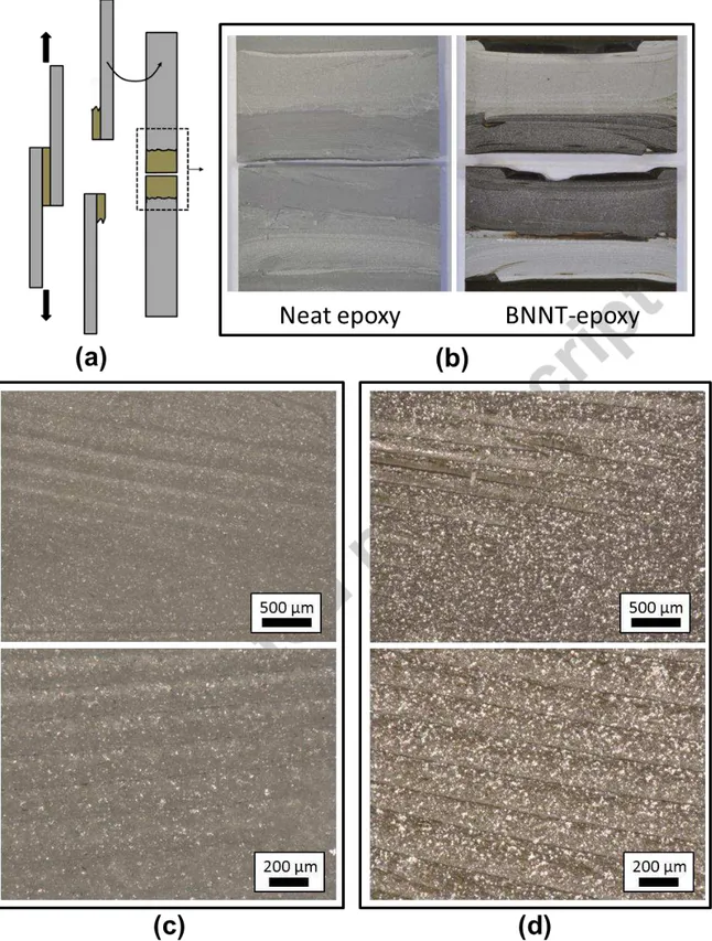
Figure 8. (a) Schematic illustration of the adhesive failure involving both adherends. (b) Photographs and (c,d) optical microscopy images of the failure surfaces (c: neat epoxy, d: 2wt% r-BNNTs). The white specks in the optical micrographs indicate metal from the aluminum adherends as discussed subsequently.
Figure 9. Lap-shear strength of Epon 828/Epikure 3223 and related BNNT composite adhesive joints using raw (r-BNNT) and purified (p-BNNT) BNNTs. Neat (repeat) is a second panel of the baseline adhesive prepared by the same method but on a different date. The error bars correspond to one standard deviation. The raw data, expressed as shear stress vs. displacement to account for small differences in the bonded area, are available as Figure S6 online.
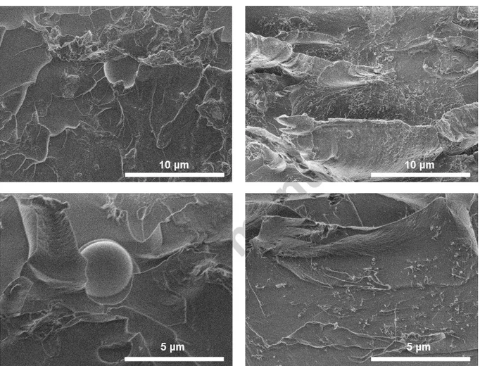
More detailed observation of the failure surfaces provides a possible explanation for the effect of nano-reinforcement. In all cases, the fracture surface followed the adhesive-adherend interfaces (as in an adhesive failure mode) but switched between the two adherend surfaces near the center of the bondline as illustrated in Figure 8(a,b) indicating failure within the adhesive itself (as in a cohesive failure mode). A qualitatively similar failure was described by Sydlik et al. [12] for the case of single-lap-shear joints reinforced with functionalized carbon nanotubes. They attributed the increased failure strength to crack deflection by the nanotubes along the transferred interface where the fracture path travels through the adhesive layer [12].The same type of failure path was observed in the present work. Optical microscopy of the failure surfaces (Figure 8 c,d) for both neat and
BNNT-reinforced joints show similar striations on the surface. In this figure, the white specks, of which there are proportionally more for the BNNT-reinforced adhesive, are thought to be metal from the aluminum adherends. The latter observation indicates that failure of the adherends also contributed to the joint failure in what is actually a mixed-mode failure (interfacial failure, failure within the adhesive, and failure within the adherend). In a single-lap-shear test, which is the most commonly used method in literature reports for nanotube-reinforced adhesives, the adherends must deform/bend as the test proceeds due to the slight tilt of the coupon (away from a perfect vertical plane) that is necessary to mount it for testing. This leads to stress concentrations in the adherends proximal to the edge of the adhesive bond and causes interlaminar failure of composite adherends [28].The failure surfaces observed in the present investigation (including the failure path switching from one adherend to the other) are consistent with this type of stress concentration. SEM images of the SLS failure surfaces (Figure 10) show the presence of many BNNTs distributed reasonably well across the failure surface, indicating that they are pulled out and therefore likely play a role in the failure by resisting crack propagation. As suggested by the work of Sydlik et al. [12], the sample was also tilted in the SEM to obtain a clear view of the crack along which failure switched from one adherend to the other (Figure 11). We observed a high instance of BNNTs protruding from the adhesive and aligned in the failure direction for joints with less BNNTs but, unexpectedly, relatively few for the highest BNNT-content adhesive (5 wt%) where performance was inferior to the baseline epoxy. This may be a key factor in the improved strength in joints with up to 2 wt% BNNTs despite the initial observation of an adhesive failure mode along the interface between the nanoreinforced adhesive and the adherend. Bending of the adherends during single-lap-shear tests also leads to a bending force (peel force) on the adhesive in addition to shear. In our previous work with CNT-enhanced epoxy for bonding composite adherends [2], we observed significant increases in peel
strength but a smaller increase (and with lower maximum nanotube content) for shear strength in a slotted single-lap-shear configuration, which prevents bending. Therefore, improved strength in the single-lap-shear test could also relate to the nanotubes improving the peel strength. Use of a slotted or double-lap configuration in future tests could provide additional insight.
Figure 10. Failure surfaces of neat (left) and BNNT-composite (right) adhesives from single lap shear tests.
4. Conclusions
Motivated by their complimentary properties to CNTs and recent advances in the availability large-scale synthesis, the joint performance of BNNT-epoxy adhesives was assessed. Modest improvements in tensile properties were obtained. In general, the elastic modulus of Epon 828/Epikure 3223 was increased, significantly and progressively with BNNT addition up to 7wt%,
but ultimate strain was reduced in all cases. The fracture toughness also increased, reaching to a plateau around 5 wt% BNNTs, and failure surfaces showed increased roughness indicating a role of BNNTs in inhibiting fracture. Single-lap-shear strength was increased despite the mixed-mode failure with a large adhesive failure contribution. Failure within the adhesive occurred near the center of the bondline and it appears that adherend failure also plays a role. These observations can be understood in relation to stress concentrations resulting from deformation of the adherends and are evidenced by the transferred interface and parts of the metal surface coming off with the adhesive. SEM images suggest that substantial pull out and alignment of BNNTs along the test direction in the region where the failure surface transitioned from one adherend to the other could be a factor in the improved performance despite failure occurring primarily at the adhesive-adherend interface. An optimum nanotube content for improvement of single-lap-shear strength was observed at 1-2 wt% BNNTs. The increased joint strength strength could also relate to the performance of the nanotube modified adhesive under bending/peel stress. BNNTs purified by removing the amorphous boron impurity led to the highest lap shear strength, 23.6 ± 0.5 MPa at 1 wt% (15% improvement relative to the unmodified epoxy), and may be a more effective reinforcement for enhancement of the joint performance. Use of purified BNNTs also reduces color and improves transparency. This work shows the potential of BNNTs to reinforce structural joints, similar to CNTs. Due to superior affinity of BNNTs for epoxy and their complimentary properties versus CNTs, they could become the preferred nanotube for adhesive reinforcement and in particular offer an alternative to CNTs when electrical insulation, optical transparency, or other unique features of BNNTs are desired.
Figure 11. SEM image of tilted (34°) lap-shear failure surfaces along the line where the failure surface transitioned from one adherend to the other. The 2 wt% r-BNNT-epoxy adhesive joint (Top) shows substantially higher alignment of the pulled out BNNTs along the failure direction than for the higher nanotube content joint (5 wt% r-BNNT; Bottom).
Acknowledgements
The authors acknowledge NRC’s Nanotube Manufacturing Facility (K.S. Kim, M. Plunkett, D. Ruth, S. Walker, C.T. Kingston) for the production and purification of BNNTs used in this work, R. Desnoyers and G. Chan for characterization support, and Matthieu Harrison and Roy Campbell for surface preparation and coupon cutting for the adhesive joint specimens. Funding to support the development of BNNT composites was provided by the National Research Council Canada through the Security Materials Technology Program.
References
1
S. Shadlou, B. Ahmadi-Moghadam, F. Taheri, Rev Adhesion Adhesives 2, 371-412, 2014 2
M.B. Jakubinek, B. Ashrafi, Y. Zhang, Y. Martinez-Rubi, C.T. Kingston, A. Johnston, B. Simard. Composites B 69, 87-93 (2015).
3
M.R. Gude, S.G. Prolongo, T. Gomez-del Rio, A. Urena. Int. J. Adhesion Adhesives 31, 695 (2011). 4
M.R. Gude, S.G. Prolongo, A. Urena. Int J Adhesion and Adhesives 62, 139-145, 2015 5
R. Mactabi, I.D. Rosca, S.V. Hoa. Compos Sci Technol 78, 1-9, 2013 6
S.G. Prolongo, M.R. Gude, A. Urena. Int. J. Adhesion Adhesives 24, 1097 (2010). 7
S.A. Meguid, Y. Sun. Mater. Design 25, 289 (2004) 8
J. Li, J.K. Lumpp, R. Andrews, D. Jacques. J. Adhes. Sci. Technol. 22, 1659 (2008). 9
J.M. Wernik, S.A. Meguid. Materials & Design 59, 19-32 (2014) 10
P. Jojibabu, M. Jagannatham, P. Haridoss, G.D.J. Ram, A.P. Deshpande, S.R. Bakshi. Composites A 82,53-64 (2016)
11
V.K. Srivastava. Int. J. Adhesion Adhesives 31, 486 (2011). 12
S.A. Sydlik, J.-H. Lee, J.J. Walish, E.L. Thomas, T.M. Swager. Carbon, 59, 109-120 (2013) 13
B. Mas, J.P. Fernandez-Blazquez, J. Duval, H. Bunyan, J.J. Vilatela. Carbon 63, 523 (2013). 14
W. Meng, Y. Huang, Y. Fu, Z. Wang, C. Zhi. J Mater Chem C 2, 10049 (2014). 15
K.S. Kim, M.J. Kim, C. Park, C.C. Fay, S.-H. Chu, C.T. Kingston, B. Simard. Semiconductor Science and Technology, 32, 013003 (2017)
16
A.L. Tiano, C. Park, J.W. Lee, H.H. Luong, L.J. Gibbons, S.-H. Chu, S.I. Applin, P. Gnoffo, S. Lowther, H.J. Kim, P.M. Danehy, J.A. Inman, S.B. Jones, J.H. Kang, G. Sauti, S.A. Thibeault, V. Yamakov, K.E. Wise, J. Su, C.C. Fay. Proc. SPIE 9060, 906006 (2014)
17
J. Ravichandran, A.G. Manoj, J. Liu, I. Manna, D.L. Carrol. Nanotechol. 19, 085712, 2008. 18
Y. Takizawa, D.D.L. Chung. J. Mater Sci 51, 3463-3480 (2016). 19
C. Zhi, Y. Bando, C. Tang, S. Honda, H. Kuwahara, D. Golberg. J Mater Res 21, 2794 (2006).
20
S.-J. Zhou, C.-Y. Ma, Y.-Y. Meng, H.-F. Su, Z. Zhu, S.-L. Deng, S.-Y. Xie, Nanotechnol 23, 055708 (2012).
21
C. Y. Zhi, Y. Bando, T. Terao, C. C. Tang, H. Kuwahara, D. Golberg, Chem Asian J 4, 1536 (2009).
22
A.T. Nasrabadi, M. Foroutan, M. Journal of Physical Chemistry C 114, 15429-15436 (2010) 23
X. Chen, L. Zhang, C. Park, C.C. Fay, X. Wang, C. Ke. Applied Physics Letters 107, 253105 (2015). 24
A. Nigues, A. Siria, P. Vincent, P. Poncharal, L. Bocquet. Nature Materials 13, 688-693 (2014) 25
Kim, K.S., Kingston, C.T., Hrdina, A., Jakubinek, M.B., Guan, J., Plunkett, M., and Simard, B. ACS Nano 8 (2014): 6211-6220.
26
X. Wang, C. Zhi, Q. Weng, Y. Bando, D. Golberg. J Physics: Conference Series 471, 012003 (2013). 27
A.L. Morales-Cruz, J. Hurst, D. Santiago. Mater Res Soc Symp Proc 1767, 145-151 (2015). 28