COLLECTIVE HYDRODYNAMICS OF SOFT MICROPARTICLES IN QUASI-TWO-DIMENSIONAL CONFINEMENT
by
WILLIAM ERIC USPAL
B.Phil., Engineering Physics, Mathematics, and Philosophy, University of Pittsburgh
(2007)
Submitted to the Department of Physics
in partial fulfillment of the requirements for the degree of
Doctor of Philosophy in Physics
at the
MASSACHUSETTS INSTITUTE OF TECHNOLOGY
February 2014
@
Massachusetts Institute of Technology 2014. All rights reserved.
__Signature redacted
Author__
/Certified by.
Department of Physics
October 7, 2013
Signature redacted
Patrick S. Doyle
Singapore Research Professor of Chemical Engineering
I I , /
Thesis
SupervisorCertified by
Signature redacted
Mehran Kardar
Francis Fr edman rofessor of Physics
Thesis Supervisor
Signature redacted
Krishna Rajagopal
Associate Department Head for Education
Accepted by
MASSACHuSETTS INS1T! E OF TECHNOLOGY
JUL 0
1 2014
Abstract
Collective Hydrodynamics of Soft Microparticles in Quasi-two-dimensional Confinement
by
William Eric Uspal
Submitted to the Department of Physics on October 7, 2013, in partial fulfillment of the
requirements for the degree of Doctor of Philosophy in Physics
Abstract
Flow of microparticles through geometrically confined spaces is a core element of most microflu-idic technologies. Flowing particles are typically ordered and manipulated with external forces or coflowing streams, but these methods can be limited in generality and scalability. New techniques to control particle trajectories would enable new applications in such areas as materials assembly, optofluidics, and miniaturized "on-chip" bioassays and cytometry.
Recently, researchers have sought to understand the conditions under which particles can or-ganize themselves through interactions generic to the flow of suspensions through microchannels. In particular, a particle moving through a viscous fluid will create a disturbance flow, affecting the motion of distant particles. These hydrodynamic interactions (HI) are sensitive to particle shape and the presence of confining boundaries. This sensitivity presents a powerful opportunity: particle trajectories could be "programmed" into particle morphology and channel design. These could chosen so that many-body hydrodynamic interactions drive self-organization of the desired particle motions. Even a single particle could be designed to "self-steer" to a desired position in the channel cross-section through its hydrodynamic self-interaction.
In this thesis, we present a series of studies exploring new possibilities for achieving self-organization, self-steering, and other flow-driven collective phenomena via design of particle shape and channel geometry. We focus on a particular setting: quasi-two-dimensional (q2D) confinement, in which particles are tightly "sandwiched" between parallel plates, free to move in only two dimen-sions. In this confinement regime, hydrodynamic interactions take a unique dipolar form. This form had been shown to sustain novel collective phenomena with much greater spatiotemporal coherence than can be achieved in unconfined or weakly confined suspensions. However, self-organization of
q2D suspensions had not been demonstrated prior to our studies.
Starting from a two-body problem, we progressively consider larger numbers of particles and more complex particle shapes. In our first study, we develop model equations for the coupled motion of two discs in a quasi-two-dimensional channel. Numerically, we find that a pair can form a hydrodynamic bound state with complex oscillatory motion. We demonstrate that this "quasiparticle" can be manipulated via patterning of confining boundaries. In the following study, we consider larger clusters of discs. We provide symmetry principles for the a priori construction of "flowing crystals": configurations of particles that maintain their relative positions as they are carried by the flow. The crystalline states generalize the two-body bound state to more complex configurations and collective modes. We also consider the wider dynamical landscape, finding
Abstract
metastable states with new, exquisitely coordinated particle motions. However, neither flowing crystals nor metastable states spontaneously form from a disordered configuration of discs.
In pursuit of self-steering and self-organization, we turn to particle shape, and study the dy-namics of a single "dumbbell" comprising two connected discs. We find that a fore-aft asymmetric dumbbell will reliably align with the flow and focus to the channel centerline. In contrast, a symmetric particle will oscillate between the channel side walls indefinitely. Through theoretical arguments, we isolate three viscous hydrodynamic mechanisms that together produce self-steering, and which generically occur for asymmetric particles in q2D. We carry out experiments with Con-tinuous Flow Lithography (CFL), finding qualitative and semi-quantitative agreement with our theoretical predictions. Obtaining statistics from hundreds of particle trajectories, we provide a convincing experimental demonstration of self-steering for device applications. To our knowledge, this study provides the first demonstration that rigid particles can focus to the centerline in a channel flow.
This progression culminates in our final study. Inspired by the mobility formalism of polymer dynamics, we develop a theoretical and numerical framework that can recover the collective dynam-ics of many particles with complex shape. We find that small clusters of dumbbells can self-organize from disorder into one-dimensional flowing crystals. However, dumbbells can also pair as undesir-able "defects." This two-body effect frustrates self-organization in large suspensions of dumbbells, driving formation of particle aggregates. To tame this aggregation, we rationally redesign particle shape, tailoring hydrodynamic interactions to promote chaining of particles in the flow direction. The redesigned "trumbbell" particles self-organize into large, two-dimensional flowing crystals. We reveal how crystal self-organization occurs through a multistage process. One, two, several, and finally many-body interactions become implicated in successive stages. This study is the first to demonstrate that flowing lattices can be stabilized purely by viscous hydrodynamic interactions. Thesis Supervisor: Patrick S. Doyle
Title: Singapore Research Professor of Chemical Engineering Thesis Supervisor: Mehran Kardar
Title: Francis Friedman Professor of Physics 4
Acknowledgments
Earning a Ph.D. has been the toughest and most rewarding experience of my life. Like so many other graduate students, I struggled initially. Callow dreams of Nature papers and scaling the dizzying heights of theory were frustrated by my own callow approach to research. Then, at some point - or perhaps it came as a slowly dawning realization - I decided I really wanted a Ph.D. I wanted a Ph.D. not in some idle sense (like I want, as I write this, to learn Boeotian Greek), but in the sense that I perceived just what it would take and I accepted the full measure of work it would require. I embraced my project as more than just a means of support, or just one dilletantish interest among many. I took it as a rare opportunity to do work of some enduring significance and to put my own stamp on it.
Many people have supported me during this process. Among them, my advisor, Pat Doyle, deserves the greatest thanks. Pat instilled in me a desire to obtain the most universal and far-reaching results - to sift the essence of a problem from the mere details, and to approach it from physical fundamentals. He could always point me in the right direction when I was lost, while giving me the autonomy to explore and learn on my own. Pat knew when to push me to achieve more and when to hold back - especially during the trying early years of my Ph.D. I would recommend him as a graduate advisor with the highest enthusiasm.
H. Burak Eral has been a patient, kind, and talented experimental collaborator. The full impact of this work really owes to his tireless efforts in the laboratory. The summer we spent working to achieve the results of Chapter 5 was intense and exhilarating - it was truly the high point of my
graduate career. I have benefited from many stimulating research conversations with him. More generally, I have learned from his healthy and balanced approach to life in research.
My interest in soft matter was first stirred by my undergraduate thesis research advisor, Anna C.
Balazs. My aspiration of achieving complex and adaptive materials behavior via creative application of physical law is shamelessly cribbed from her. This aspiration will drive my research so long as
I work in academia - possibly for life. In her group, I had the pleasure of closely working with Dr. Kurt Smith and Dr. Alexander Alexeev. I look forward to seeing Alik at future research conferences, and avidly follow the work of his own recently formed group at Georgia Tech. I am also grateful to my other undergraduate research sponsors - Riidiger Dieckmann, Seong H. Kim, and especially Wolfgang J. Choyke - for their mentorship and the opportunity to work in their laboratories.
I am privileged to have a tight-knit group of friends at the Institute: Jeremy Green, Christopher Leon, Matthew Schram, Alexander Soane, and Arturs and Nora Vrublevskis. My spirits were kept high by the daily patter of email (Gmail lists 4,500 threaded conversations), visits to the gym, and many nights of interesting (and sometimes "interesting") discussion over beer and pizza.
The Doyle group has been a fun and supportive environment throughout the years. I specifically would like to thank the graduate students and postdocs who most overlapped with me: Harry An (bearer of many nicknames), Rathi Srinivas (who answered Bill's panicked midnight calls, assuring him he hadn't destroyed the SFL setup), Ben Renner (for many wide-ranging discussions), Ki Wan Bong (kind neighbor), Daniel Trahan (the undisputed U.S. Senate trivia champion), Charles Mitchell, Matt Helgeson, and Jeremy Jones.
Finally, I would like to thank my family for their love and support. I note that, like Dr. Neil Uspal and Dr. Julie Uspal Zarnoch, I've done my part, and when Jennifer Uspal finishes med school, we'll at last be able to call David Uspal, M.S. the Howard Wolowitz of the family. (Additionally,
I'd like to thank David Uspal for being a good sport.)
My first year at the Institute was generously supported by a Whiteman Fellowship administered by the Department of Physics. The work in this thesis was supported by a grant from the Institute
for Collaborative Biotechnologies through contract no. W911NF-09-D-0001 from the U.S. Army Research Office. The content of the information does not necessarily reflect the position or the policy of the Government, and no official endorsement should be inferred.
Table of Contents
Abstract Chapter 1 Introduction 1.1 M otivation . . . . 1.1.1 Microfluidic technologies . . . . 1.1.2 Fundamental microhydrodynamics. . . . .1.1.3 Non-equilibrium self-organization and self-steering . . . . 1.2 Objectives and overview of studies . . . .
Chapter 2 Background
2.1 Particle-laden flows: General considerations . . . .
2.2 The Stokes equation . . . . 2.2.1 Linearity . . . . 2.2.2 Instantaneity . . . .
2.2.3 Reversibility . . . .
2.2.4 Additional properties of the Stokes equation . . . .
2.3 Flow singularities and hydrodynamic interactions . . . .
2.3.1 The Stokeslet . . . .
2.3.2 Other fundamental flow singularities . . . .
3 25 25 25 26 27 28 31 32 34 35 35 36 36 37 37 39
2.3.3 Geometric confinement and the method of images . . . . 2.4 Sedimentation . . . . 2.4.1 Two coupled Stokeslets . . . . 2.4.2 Many-body sedimentation . . . .
2.5 Particle motion in microchannels . . . .
2.5.1 Self-steering and self-organizing particles . . . .
2.5.2 Quasi-two-dimensional confinement . . . .
Chapter 3 Two discs flowing in a quasi-two-dimensional 3.1 3.2 3.3 3.4 3.5 3.6 3.7 3.8 3.9 Overview . . . . Introduction.. ... . .... ... .. .. .
Equations of motion and numerical method . . . .
Unbounded q2D . . . .
Confining side walls . . . .
Behaviors and phase map . . . . Characterization of nonlinear oscillations . . . . Bound state manipulation through patterned side walls Conclusions . . . .
Chapter 4 Collective dynamics of multiple discs
4.1 Overview . . . . 4.2 Introduction . . . . 4.3 Theoretical model . . . . 4.4 Lattice Boltzmann Method . . . .
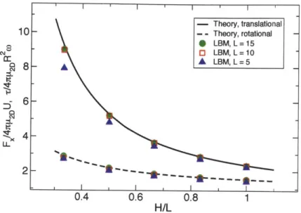
4.4.1 Validation: Torque and drag on a single disc . . . . 4.5 R esults . . . .
4.5.1 Two discs, revisited . . . . 4.5.2 Fixed points and oscillatory modes . . . . 4.5.3 Metastable states and stochastic dispersion . . . . . 4.5.4 Cyclical dynamical motifs . . . . 4.6 Conclusions . . . .
Chapter 5 Engineering the trajectory of a single particle 5.1 Overview . . . .
5.2 Introduction . . . .
5.3 Model equations and numerical method . . . .
5.3.1 Force-free equation for a single disc . . . .
5.3.2 Additional equations and numerical method . . 5.4 Experimental method . . . .
5.5 Self-alignment of asymmetric particles under flow . . . . .
5.5.1 Experimental observation of self-alignment . . . . .
5.5.2 Derivation of equation for self-alignment . . . .
,hannel 47 . . . . 48 .. . . .. .... ... .. 48 . . . . 49 . . . . 50 . . . . 53 . . . . 56 . . . . 58 . . . . 59 . . . . 61 63 . . . . 64 . . . . 64 . . . . 66 . . . *. 67 . . . . 69 . . . . 69 . . . . 70 . . . . 72 . . . . 76 . . . . 78 . . . . 79 via particle shape
5.6 Dynamics of dumbbells in a microchannel: The complete picture . . . . 5.6.1 Derivation of numerical and theoretical phase boundaries . . . . 5.6.2 Experimental observation of focusing . . . .
83 84 84 85 87 88 89 90 91 92 94 96 100 40 40 41 43 43 44 45
5.7 Additional results . . . .
5.7.1 Focusing is rapid near the critical boundary
5.7.2 Reversibility of focusing dynamics . . . . .
5.7.3 Conditions for global assembly . . . .
5.8 Conclusions . . . . Chapter 6 Self-organization of flowing crystals
6.1 Overview . . . .
6.2 Introduction . . . .
6.3 Theory and numerical method . . . . 6.3.1 Motion of a single disc . . . .
6.3.2 Systems of multiple discs . . . .
6.3.3 Mobility tensor . . . . 6.3.4 Particle architecture and conservative forces . . . .
6.3.5 Numerical integration scheme . . . . 6.4 R esults . . . .
6.4.1 Small cluster of dumbbells . . . . 6.4.2 Dumbbell suspension . . . . 6.4.3 Engineering hydrodynamic interactions via particle shape . 6.4.4 Trumbbell suspensions . . . . 6.5 Conclusions . . . . 109 . . .. ... 110 ... 110 . ... .... 113 . ... 113 . . . 115 . ... 115 . ... 116 . ... 117 . ... 117 . . . 118 . . . 118 . ... 121 . . . 125 . . .. ... 134 Chapter 7 Summary and Outlook
Appendix A Single disc flow field
Appendix B Hydrodynamic interaction tensor Appendix C Effect of disc rotations
137
141 143 145 149 Appendix D Order parameters
103 103 103 105 107
List of Figures
2.1 A point force (green vector) applied to a suspended sphere creates a disturbance flow
in the surrounding fluid. We show the leading order, far-field contribution to this
flow, known as the "Stokeslet." . . . 37
2.2 The Green's function for a point force is changed by geometric confinement: the flow must satisfy the no-slip and no-penetration conditions on each solid boundary. For a plane wall, both the Stokes equation in the fluid domain and the boundary conditions on the wall can be satisfied with a system of images. A point force (green vector) at height y = h above the wall creates at y = -h an oppositely directed image force, a force dipole, and a mass dipole. The blue vector represents all three im age singularities. . . . 41
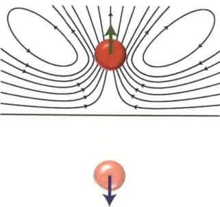
2.3 Reversibility implies that a sphere sedimenting near a wall experiences no lift force. In (a), we assume the sphere has a non-zero velocity component in the wall normal direction. In (b), we reverse the driving force. Reversibility requires that the sphere velocity also be reversed. In (c), we rotate the coordinate system of the sphere/wall system, obtaining the same physical situation as in (a). However, the normal com-ponent of sphere velocity is negated relative to (a). Therefore, the assumption of a non-zero normal component is contradictory. . . . 42
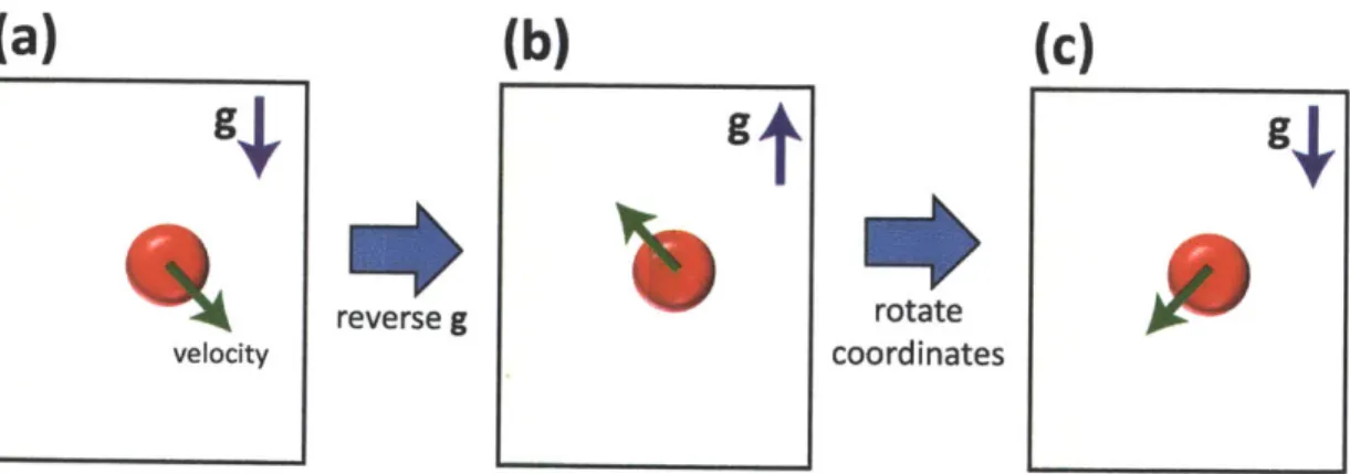
2.4 A polymer can be represented as a "dumbbell": two beads connected by a spring.
In a shear flow, the spring is stretched, introducing point forces that disturb the background flow. We show the disturbance field created by the force on the left bead. This disturbance drives the right bead away from the wall. Likewise, the right bead drives the left bead away from the wall by the flow disturbance it creates. . . 44
2.5 Illustration of quasi-2D hydrodynamics. A disc is tightly confined between parallel plates and subject to an external flow (black vectors). The particle is advected downstream (blue vector) by the flow. However, due to strong friction from the confining plates, the particle lags the external flow, and moves upstream relative to it (green vector). The particle therefore creates a characteristic dipolar flow disturbance field; fluid mass is pushed away from its upstream edge and drawn into its downstream edge. . . . . 45
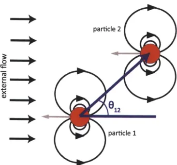
3.1 Two hydrodynamically coupled discs in an unbounded quasi-two-dimensional ge-ometry are driven by a uniform external flow. The discs interact via dipolar flow disturbance fields. For 012
$
0' and 012$
900, the discs can have a non-zero veloc-ity component perpendicular to the external flow field. However, they cannot move relatively for any configuration. . . . . 52 3.2 The lateral drift velocity of two flow-driven hydrodynamically coupled discs inun-bounded q2D as a function of pair angle. The red curve is given by the theoretical expression in Eq. 3.17. The black data points were obtained numerically. We vary
angle for fixed disc separation r = 5R, B = 2.12, and
a
= 0.796. . . . . 543.3 System of real and image discs used to obtain the "dressed" or effective hydrodynamic
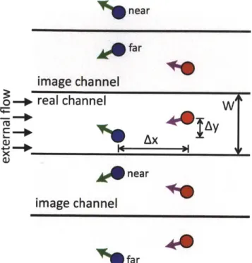
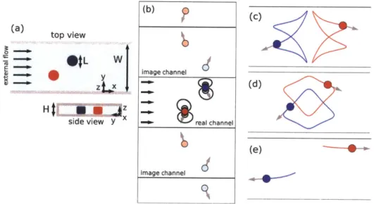
interaction tensor in a quasi-two-dimensional channel. A discs' images split into sets designated "near" and "far," generated as periodic copies of the two closest images with periodicity 2W . . . 55 3.4 (a) Particles of length L are confined to two dimensional motion in a channel of
width W and height H, where H < L < W, and subject to an external flow. (b) Top down view of the system of images used to impose the no-mass flux condition at the channel side walls. The real particles (dark red and dark blue) are dressed
by an infinite set of images (light colors). The particles lag the external flow and
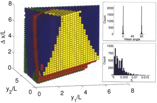
are therefore coupled by dipolar flow disturbance fields. Gray vectors are particle velocities in a frame moving with the x component of the particles' center of mass, Xcen. (c) Particle trajectories in the xen frame for oscillation around a 00 fixed point, as described in the text. (d) Particle trajectories around a 90' fixed point. (e) A scattering event. . . . . 56 3.5 Phase map indicating behavior for the initial condition (yi, y2, Ax). Yellow (light)
squares indicate oscillation around a 00 fixed point; green (light) triangles, a 90' fixed point; blue (dark) squares, scattering; and red (medium) circles, particle-particle or particle-wall overlap. For the oscillatory trajectories, the inset figures show the distributions of mean angle and frequency, where fL is found by taking the spatial Fourier transform as described in the text. . . . . 57
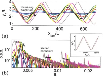
3.6 (a) Position of a particle in y with xe, for initial separation Ay = 3L and Ax = 0
and various initial displacements of ye, from the centerline, where the fixed point has yi/L = 2.5. (b) Matched by color, the power spectra of the trajectories in
(a), where
f
has units of inverse length. fo is predicted by linear theory. Arrows indicate the shift of peaks with increasing amplitude. The appearance of second harmonics is linked to the breaking of the half-wave symmetry yi(xem+A/2) -2.5L =-(yi (xm) -2.5L), where A is the signal wavelength. The inset shows both the largest
amplitude trajectory from (a) and the result of performing the symmetry operation on it; the curves do not coincide. . . . 58
3.7 Effective potentials in Ax (a) and y, (c) for the trajectories in Fig. 3.6, matched
by color. The potentials are shifted and rescaled for characterization in the
Cheby-shev basis. (b) For motion in Ax, a negative coefficient of T4 for large amplitude oscillations indicates a softening nonlinearity. (d) For motion in yi, large ampli-tude oscillations have skewed potentials, consistent with the half-wave symmetry breaking. Arrows indicate the effect of increasing amplitude. . . . 59
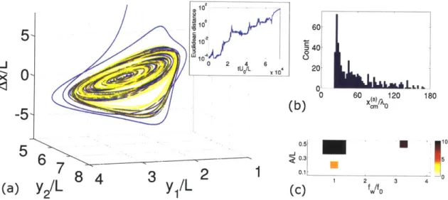
3.8 (a) Phase portrait of two trajectories with A/L = 0.2 and f"/fo = 1 initially sep-arated by a noise vector in phase space with magnitude
E
= 10-4. The trajectories diverge exponentially (inset). (b) Distribution of scattering length x( , for A/L = 0.2 and f,/fo = 1. (c) Number of scattering and overlap trajectories for variousam-plitudes and spatial frequencies of a sinusoidal pattern. The results for irrational frequency ratios are similar. . . . . 60
4.1 (a) In this chapter, a cluster of N particles (here N = 3) is tightly confined in a
gap of height H between plates normal to the z direction. They are free to move in x and y between side walls, where W is the width of the channel. The position of particle i is labeled by xi and yi in a frame fixed to the channel walls. The particles are driven by an external flow. (b) System of real and virtual particles used to derive the thin channel hydrodynamic interaction tensor. The real particles (dark colors) are subject to an external flow (black vectors) and are dressed by an infinite set of images (light colors) that are constructed iteratively, via mirror reflections across the real and virtual channel boundaries. Due to friction from the confining plates, each particle lags its own local flow field; gray vectors show the velocities of the real particles in frames moving with local flow. This relative motion gives rise to hydrodynamic disturbance fields (black streamlines) that couple the particles, and is dominated by motion in the direction opposed to that of external flow. We also show particle velocity in a frame moving with the particle cluster's center of mass for two of the virtual particles (green vectors). . . . . 65
4.2 Dimensionless drag forces and torques vs. dimensionless channel height H/L for a disc translating or rotating in a quiescent fluid for various disc sizes L, where L characterizes the level of spatial coarse-graining. For L = 10, the disc size used in
4.3 (left) Oscillation of a particle pair with initial Ay = 3L, initial Ax = 0 and initial
center of mass position y,, = W/2 + L. The positions of the two particles in
y are shown as a function of center of mass position x,,. The solid black curve shows LBM simulation results at Re = 0.2, and the dashed red curve shows the
result of numerically integrating the theoretical model. These curves closely agree, though very slight attenuation in amplitude can be seen in the LBM results. (right) Simulation results for the particle pair, shown after advection by xe,,/L = 859
particle lengths. The red and blue curves show particle positions at prior times, and crosses indicate initial particle positions. Colors indicate the magnitude of the fluid velocity field. . . . 71 4.4 Oscillation of a particle pair with initial separation Ay = 2L, Ax = 0 and initial
center of mass position yc.. = W/2 + L for various values of Re. Particle positions in
y are shown as a function of center of mass position x,, in the flow direction. As Re
decreases, there is less decay of amplitude per wavelength. For clarity, we omitted the theoretical curve for one of the particles . . . 72 4.5 The two particle configuration of Figure 4.4 has an characteristic wavelength A/L
with which yi and Y2 oscillate as xcer increases. This wavelength A/L scales with the hydrodynamic interaction parameter 3 with a fitted exponent of -0.963, close to the predicted value of -1. . . . 73
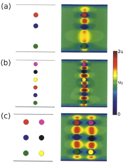
4.6 Fixed points obtained a priori via symmetry considerations, depicted in top down view. The first column shows particles in a frame moving in the center of mass when the theoretical model is integrated. In this frame, particles remain in fixed positions. Side walls are indicated by black lines. The second column shows particles in the center of mass frame for the corresponding Lattice Boltzmann simulations. Colors indicate the magnitude of the fluid velocity field. In the simulations, particles move slightly, but remain within one radius of their initial positions. Due to this motion, the fluid velocity field can be slightly asymmetric. (a) A "dimer column" for channel width W/L = 9. The LBM simulation is shown after the particles were advected
downstream by xe,,/L = 241 particle lengths at Re = 0.2, where xc,, is the position of the center of mass in the flow direction. (b) A "column" fixed point and LBM simulation after advection by x,,/L = 833 particle lengths at Re = 0.2. (c) A "double column" fixed point and LBM simulation after advection by xe,,/L = 524 particle lengths at Re = 0.2. . . . 74
4.7 Geometric construction of the "dimer column" fixed point. In (a), three real particles are accompanied by an infinite set of virtual particles, the closest of which are at
y = -a/2, y = W + b/2, and y = W + b/2 + a. These quantities are related
by 3(a + b) = 2W. Each of the real and virtual particles is identical, resembling the particle shown in (b), moving in -x with respect to the local flow field and contributing components of velocity in positive x to the local flow fields of the other particles. The gray vector shows the velocity of a particle with respect to the local
flow, while the black streamlines illustrate the dipolar disturbance field thus created.
Because this configuration is one dimensional, the angular dependence of the dipolar form is not relevant here. . . . . 75
4.8 Oscillatory modes of a three particle column fixed point with W/L = 8 and lattice
length a/L = 8/3. The top row shows trajectories found via numerical integration
of the theoretical model, starting from an initial condition in which the particles are displaced from the fixed point along an eigenvector. In the bottom row we show the corresponding LBM simulations. Particles are shown in their final positions, while the crosses indicate initial positions. The red, blue, and green curves are the "tracks" showing particle positions over time. Arrows indicate the direction of particle motion. In the simulations, the oscillations in (a) slowly grow with time, while those in (b) slowly decay. As discussed in the text, this effect diminishes as Re is decreased. (a) Theory and simulation results after x,/L = 482 advected particle lengths. For the simulations, Re = 0.2. The particles were initially displaced from the fixed point
by Ay1 = -0.34L, where particle 1 is the green (bottom) particle; Ay2 = -0.68L,
for the blue (middle) particle; and Ay3 = -0.34L for the red (top) particle. (b)
Results after x,,/L = 205 advected particle lengths. For the simulations, Re = 0.05.
The initial displacements from the fixed point are Ax1 = -0.22L, Ax2 = -0.43L,
and Ax3 = -0.22L. In contrast with (a), here Re and x,,/L are too small for a
discernible phase difference between theory and simulations. . . . . 77
4.9 Snapshots of simulation results for a metastable steady "triangle" configuration with Re = 0.2 and W/L = 8 at four values of the cluster center of mass x,. Particle
motion, initially limited to small excursions from the initial positions, grows in mag-nitude until the magenta and green particles pair. Ultimately, the red and green particles escape together. Colors indicate the magnitude of the fluid velocity. . . . . 78 4.10 Dispersion c.2/L 2 with dimensionless time Uot/L for four trajectories of the metastable
"triangle" configuration of Figure 4.9, simulated with the Lattice Boltzmann method. For each trajectory, the initial particle positions are spatially perturbed by a displace-ment vector with magnitude 0.025L and random angle. The four trajectories break up at different times. . . . 79 4.11 (a) Particle motion in the center of mass frame for two realizations of a metastable
three particle configuration with W/L = 8, as determined by integration of the
the-oretical model. The two realizations differ by slight noise in the initial particle posi-tions. A random perturbation uniformly distributed over the interval [-0.0125L, 0.0125L] is applied to the x and y positions of each particle. The green (middle) particle pairs and escapes with either the red (left) particle, as shown in the first panel, or the blue (right) particle, as shown in the second panel. (b) Distribution of escape pathways for the three particle configuration. Bins are labeled by which two particles pair. For each trajectory, the initial particle positions are given a random perturbation, as in (a). The escape outcome is sensitive to this perturbation. (c) Euclidean distance
A2(t) = EZ[(Xi,A(t) - xiB(t))2 + (yi,A(t) - Yi,B(t))2] between the two realizations
(trajectories in phase space) in (a) as a function of dimensionless time, where i in-dexes the three particles, and A and B label the two trajectories. For some initial transient period, both trajectories are bound as three particle configurations and diverge exponentially in phase space, A ~ eAUot/L, with a Lyapunov exponent of
4.12 Cyclical motifs for N = 3 particles discovered via a "brute force" search with the
theoretical model and confirmed with LBM simulations. In a search, we sweep over initial spatial configurations of N particles, integrating the model forward in time for a specified time span and identifying candidate cycles as those with small Euclidean distance between the initial and final spatial configurations. The Euclidean distance
d is defined as d2 = Ei[(Xi(tfinai) - X,(0))2 + (y,(tfnal) -
yi(0))
2].
The simplicity of the model makes this approach computationally tractable. Colors indicate the magnitude of the fluid velocity field. (a) In the "juggling" motif, the three particles move clockwise, as indicated by the black arrow, cyclically exchanging positions. Particles pause in the bottom position, recalling how a juggler will momentarily have a ball in hand. Each exchange of particle positions occurs after about 115 advected particle lengths, so that the entire cycle takes about xm/L = 345 lengths.(b) The "bowtie" motif. At first glance, it might appear that this motif is associated
with a fixed point in which particles are positioned on the centerline, aligned with the flow. However, such a configuration would quickly disperse. Particles return roughly to their initial positions after approximately xc/L = 960 particle lengths. 82 5.1 Schematic diagram of the model system. A particle comprising two rigidly connected
discs is confined in a thin microchannel of height H and width W and driven by an external flow. The flow is approximately uniform in the channel midplane, and has depth averaged velocity U0. The disc radii are R1 and R2, with R1 > R2, and the disc centers are separated by distance s. Two thin lubricating fluid layers of height h separate the discs from the confining plates (i.e. the channel "ceiling" and "floor.") The instantaneous particle configuration is specified by two coordinates: the location in y of the midpoint between disc centers, yc = (Y1 + y2)/ 2, and the angle 0 between the external flow and the particle axis. . . . 86 5.2 A symmetric particle oscillates between side walls. When the symmetry is slightly
broken, this oscillation is damped, and the particle aligns with the flow as it focuses to the centerline. A very asymmetric particle is "overdamped," and rapidly aligns before slowly focusing. The trajectories were obtained numerically for the parameters given in the caption of Fig. 5.12b. The x axes are scaled by a factor of 1/40 to show the full range of particle behaviors. . . . 87 5.3 Comparison of models for flow of a disc. We show
a
as a function of h for fourvalues of H as determined by our simplified model and the more detailed analysis of Halpern and Secomb. Our simplified model shows good quantitative agreement for small H and captures the trends in h and H. . . . 89
5.4 This photograph of the experimental setup shows the microfluidic channel, the mov-ing microscope stage and continuous flow lithography setup, and the camera. The inset shows a zoomed in view of the PDMS channel with ruler markings. The scale bar is 100 um . . . . 90 5.5 Hydrodynamic self-interaction drives alignment of an asymmetric particle. (a)
Il-lustration of the self-interaction of a symmetric particle. A disc's vector shows the component of the flow disturbance from the other disc in 0, the direction of increas-ing 0. The vectors are identical: there is no rotation of the particle. (b) When the two discs have different radii, the particle aligns with the flow. . . . 91
5.6 Experimental angle vs. time for various R with 9 = 3.3, h = 0.06, and H = 1.6. We scale the data for each f by a fitted
i,
collapsing all data onto a universal curve predicted by theory. (inset) The dependence of the experimental timescales r on R, along with a theoretical curve for the same parameters (solid) and a theoretical curve with h adjusted for best fit (dashed). . . . . 92 5.7 Experimental images of particle self-alignment. (a) Snapshots of a symmetric particleat various times, matched to the times in Fig. 5.6. The scale bar is 100 pm. (b) Snapshots for R = 2 at the same times as in (a). . . . 93
5.8 A symmetric particle oscillates via the combined effects of hydrodynamic interaction
with itself and with its own images. Self-interaction leads to cross-streamline migra-tion ("lateral drift") when the particle angle 9
$
0' and0
51 900. The images rotate the particle. . . . 955.9 Portraits showing particle trajectories in the phase space (y,, 9). Portraits were
obtained numerically for W = 21, § = 3.5, H = 1.6, and h = 0.08. Arrows give
direction of motion in phase space. Dots identify the trajectories shown in Fig. 5.2.. 96 5.10 Linearized model of an asymmetric particle. Rotation by the images is opposed by
self-alignment. The particle drifts in the y direction when
0
is displaced from theequilibrium value 0 = 00. The lateral displacement A is defined as A =- y, - W/2. . 97
5.11 Theoretical and numerical critical boundaries. For various sets of parameters H, §, R, and h, we numerically obtain points on the critical boundary separating the
underdamped and overdamped oscillatory regimes via the method described in the section "Numerical Phase Boundary." These points are shown as symbols in the figure. For each parameter set, we also obtain theoretical curves via Eqs. 5.18 and
5.19, shown as solid lines and matched to the symbols by color. Each curve fits its
corresponding numerical data with the same fitted dimensionless prefactor of 1/3. Moreover, as shown in Fig. 5.12, all curves and data can be collapsed onto a single
boundary via an empirically fitted rescaling of §-1/5 1/6 V. For clarity, not all of
the parameter sets in the collapsed Fig. 5.12 are shown. . . . . 98 5.12 Phase diagram showing the critical boundary that separates the underdamped and
overdamped regimes. The symbols are points on the boundary obtained numerically for various parameters. The solid lines, matched by color to the symbols, are theo-retical curves for the same parameters. The numerical data and theotheo-retical curves collapse onto one universal boundary . . . 99
5.13 Individual particle trajectories. All scale bars are 100 Am. (a) Experimental montage
showing reflection of a symmetric particle. The corresponding theoretical trajectory is shown in the inset. (b) A strongly asymmetric particle with
0
= -10* focuses tothe centerline. (c) A strongly asymmetric particle with a large initial angle aligns and then focuses to the centerline. (d) Position data for the trajectory in (a). The theoretical trajectory for R = 1 was scaled in x by a factor of 0.475. A theoretical
curve with R = 1.01, for which the rescaling is 0.4, better captures the curvature of
the data. (e) For the particle in (b), the rescaling is 0.15. (f) For the two timescale process of (c), different rescalings of 3 and 0.1 are required to capture the initial and steady dynamics. For all trajectories, § = 3.3, h = 0.3, and H = 1.6. . . . 101
5.14 Statistics of particles in a flow-through device. (a) Fluorescence microscopy image of symmetric and asymmetric particles flowing in a channel. The asymmetric particles focus to the centerline (red). The white lines indicate the channel side walls. The scale bar is 100 pm. (b) Distributions of transverse positions for symmetric particles (R = 1) measured near the inlet (blue, left hatching) and outlet (red, right hatching).
Both distributions are nearly uniform across the channel width. (c). Distributions of transverse positions for the asymmetric particles (R = 1.3). The particles begin
nearly uniformly distributed at the inlet. Most focus to the centerline near the outlet. Statistics are gathered from over 300 symmetric and 300 asymmetric particle trajectories. . . . 102
5.15 Position of a particle in a channel for various asymmetries f, initial condition
(yc,O) = (W/4,1600) at xc = 0, and parameters h = 0.08, H = 1.6, W = 21, and 9 = 3.5. The most rapid convergence to y, = W/2 with xc occurs for R at the
critical value of Rcrit = 1.10. . . . 103 5.16 Demonstration of the reversibility of the dynamics of an asymmetric particle via
numerical integration of the governing equations. A particle initially with y, = W/4
and 9 = 450, as indicated, is advected by the flow Uo = Uoi until time t = T, where T 300. At this time, the particle is nearly aligned and focused. The flow is
reversed, and the particle retraces its trajectory and recovers its initial configuration after an additional time T. Thereafter, it rotates into a configuration with 9 = 900.
The entire trajectory is mirror symmetric across this configuration. Ultimately, the particle aligns with the reversed flow -Uo0 and focuses to the centerline. To show
the full range of particle motion, the x axis has been compressed by a factor of 10. 104
5.17 (a) For a weakly asymmetric particle at its 9 = 900 fixed point, the large disc is close
to the nearest images, interacting more strongly with them than the small disc does. The tendency of the particle to self-align is exactly balanced by the stronger flow
field experienced by the large disc. Here, R = 1.05, h = 0.08, H = 1.6, . = 3.5, and
W = 21, and the fixed point occurs at yc/W = 0.192. (b) These fixed points are
marginally stable. For a small initial displacement from the fixed point, the particle appears to "bounce" along the wall as it is advected down the channel. The x axis is compressed by a factor of 20 in this image. . . . 106
6.1 (a) A single aligned and focus particle is part of an infinite lattice of real and image particles. When one or more image particles are exchanged for real particles, the re-sulting configuration should also steadily translate along the channel with no relative particle motion. Each of the real and image particles is separated by W/N, where
N is the number of real particles. (b) An infinite two-dimensional lattice should
likewise steadily translate. The lattice length a is determined by particle density. . 111
6.2 Particle architectures considered in this work. A dumbbell comprises hydrodynam-ically interacting discs, with f = R1
/R
2 = 1.5. The disc centers are connected by a stiff Hookean spring with equilibrium length § = s/R 2 = 3.5. A trumbbell has two "tails" separated by angle4=
50'. The two tail discs are connected by a thirdstiff spring (not shown) so that this angle remains fixed. Through hydrodynamic self-interaction, both the dumbbell and trumbbell align under flow so that the head disc is upstream . . . 112
6.3 (a) Trajectories of an isolated pair of dumbbells from one hundred random initial conditions. Blue and green curves are obtained from each run as the y positions of the two head discs plotted against the pair center of mass x. A majority of
dumbbells focus to the centerline; these trajectories have a characteristic exponential envelope. A substantial number focus to the doublet crystal positions y/W = 1/4 and y/W = 3/4. Other pairs form stable defects that are attracted to positions near the side walls, or unstable but long-lived oscillatory defects that eventually break up to form doublet crystals. The channel width is W = 30. (b) Histogram of the
final head disc positions of the trajectories in (a). Approximately 20% of dumbbell pairs form doublet crystals. (c) Pair behaviors obtained in the simulations of (a). The unstable defects translate back and forth across a section of the channel width before breaking up. Singlets weakly repel each other in the flow direction; there is no steady separation in x. . . . 119
6.4 Frames from a representative simulation of a dumbbell suspension. The channel width is W = 20 and the simulation contains N = 20 dumbbells. There are periodic boundary conditions in the flow direction, and the simulation box has length
l2/W
= 7.5. Particles are labeled by number. (a) The randomly seeded initial condition. (b) A large number of particles have aggregated. The configuration of neighboringparticles in the aggregate strongly resembles the defect states obtained in Fig. 6.3. For instance, particles 9 and 20 appear to be an unstable defect, and particles 7 and 17 resemble a stable defect. (c) Particles 2, 9, 6, 5 have escaped the central aggregate. Relatively separated from each other and the rest of the suspension, they behave like isolated single particles and migrate towards the channel centerline. Downstream of the central aggregate, emerging spatial order can be discerned in particles 11, 14, 12, 16, 8, 18, and 3. (d) Particles 14, 11, 12, and 16 have formed a doublet crystal, which is moving upstream towards the aggregate. (e) Particles 11 and 16 have left the crystal, and particles 19 and 10 have been recruited to it. The crystal is approaching a stable defect (particles 13 and 1) and an unstable defect (particles 4 and 15). Further downstream, particles 3 and 18 have formed a doublet crystal. (f) One doublet crystal has broken up from encountering defects, while another (particles 3 and 18) approaches an aggregate. . . . 120
6.5 Statistics of thirty-two different runs of a dumbbell suspension with the same pa-rameters as in Fig. 6.4. Simulations are run for time t = 5.0 x 10⁴. (a) The pair correlation function g(Ax, Ay) showing the probability with which two head discs are separated by (Ax, Ay). The function is normalized by the probability function for a suspension with uniform density
#0.
The sterically excluded area is indicated by a dashed line. There is a bright ring around this region, indicating a short-range at-traction responsible for defect formation and aggregation. (b) A correlation function corrected for the variation of particle density across channel width. With thiscor-rection, peaks in pair separation at (Ax = ±W/3, Ay = 0), (Ax = ±W/2, Ay = 0),
and (Ax = t2W/3, Ay = 0), indicated by white arrows, become more clearly
visi-ble. These peaks are due to transient formation of doublet and triplet crystals. (c) The conditional correlation function g(Ax, Y2IY1 = W/6). This function expresses the probability of finding a head disc at position (xi + Ax, y2), given that a second head disc is at y1 = W/6. There are triplet crystal peaks at (AX = 0, Y2 = W/2) and (AX = 0, Y2 = 5W/6), in addition to defects surrounding the excluded volume region. The function is normalized by particle density profile in (d). (d) The varia-tion of particle density across the channel. Particles are depleted from the channel center and enriched along the side walls, as the frames in Fig. 6.4 suggest. . . . 122
6.6 (a) Disturbance flow created by a single isolated "trumbell" in unbounded q2D, cal-culated numerically. Streamlines are shown in black. The total flow disturbance is due to the superposition of dipole singularities: yellow arrows show dipoles from fric-tion on the discs, and white arrows show dipoles from internal spring forces. Notably, the streamlines are fore-aft asymmetric, bent in the downstream direction. The color field indicates the x component of the disturbance velocity. To focus attention on the far-field disturbance, we do not show the area immediately around the particle. (b) The disturbance flow field can be regarded as the sum of multipole components. The lowest order contribution is a point dipole. The quadrupolar correction bends the streamlines downstream. (c) In contrast, the disturbance streamlines for a dumb-bell are bent upstream. Accordingly, its quadrupolar correction has opposite sign as the trumbbell quadrupole. (d) Effective potentials for two dumbbells (dashed red line) and two trumbells (solid black line) aligned in the flow direction in unbounded
q2D. The quadrupolar contribution to the interaction of two dumbbells is
repul-sive. For two trumbbells, the quadrupolar component is attractive. Higher order, shorter range multipole components are repulsive, stabilizing the trumbbells against collision. As a result, two trumbbells have an equilibrium separation Aze, = 7.4. . . 123
6.7 An initially disordered suspension of trumbbells can self-organize into a two-dimensional
crystal. There are N = 20 particles in a simulation box with W = 20 and LX/W = 7.5. (a) Trumbbells are initially placed with random positions and angles. (b) The
particles have aligned with the flow. Groups of particles have locally self-organized, either laterally, as doublets, or in the streamwise direction, as strings held together
by the quadrupolar interaction. (c) The particles have entirely partitioned into two
separate lanes located near the doublet crystal positions y = W/4 and y = 3W/4. In this case, the two lanes have an equal number of particles. However, not every particle has found a partner. For some particles the partner position is vacant (e.g. particle 9.) For others, the partner is shared (e.g. particles 4, 10, 1) in a triangular configuration. (d) The particles have spread more evenly across the channel, but va-cancies and triangle formations remain. (e) The suspension now resembles a strained crystal, and is on the threshold of relaxation to an unstrained lattice. Particle 2 will capture particle 16, allowing 6 and 19 to partner. (f) The particles have settled into an apparently "perfect" crystal, and have approximately the same neighbors as in fram e (c) . . . 126
6.8 . (a) Evolution of the order parameters with center of mass position xc for the trajectory shown in Fig. 6.7. Dashed lines indicate the values of x, for the frames shown in that figure. (b) Long time evolution of the particle positions in the stream-wise direction. Aside from a small amplitude, low frequency density wave, particles positions in x are approximately evenly spaced and steady. . . . 127
6.9 Vacancy defects propagate by a simple mechanism. (a) A cluster of three isolated particles. Particles 1 and 2 are initially placed in a doublet crystal configuration, and particle 3 is placed next to particle 2. Due to dipolar HI, a doublet crystal has a greater downstream velocity than an isolated particle, since each particle in the crystal increases the local fluid velocity of its partner ("transverse anti-drag.") The crystal collides with the slower particle 3. Particle 3 slows down particle 2 and speeds up particle 1, forming a triangular configuration. Particle 1 swaps partners, leaving particle 2 upstream. (b) The same mechanism occurs in a two-dimensional crystal. As a result of defect motion, the two rows of the crystal slide past each other: particle 24 has exchanges particle 15 for particle 10, and particle 22 is about to exchange particle 2 for particle 15. . . . 128
6.10 Two vacancy defects in parallel lanes can annihilate each other on close approach.
If an equal number of particles partition to two lanes, defect annihilation precedes relaxation to a defect-free crystal. (a) Particles 27 and 14 are associated with vacan-cies. (b) Particles 27 and 14 form triangular configurations alongside particles 14 and 2. (c) Particle 12 has successfully partnered with 27, pushing particle 2 upstream. Particle 14 has not fully partnered with particle 18. (d) Instead of partnering with particle 18, particle 14 is captured by particle 2. (e) Particle 3, instead of partnering with 25, is likewise attracted to a downstream particle, particle 18. (f) A shear wave propagates down the lattice. (g) The shear wave is dissipated, and the crystal relaxes to equilibrium . . . 129
6.11 Suspensions can crystallize with two types of permanent defect. If an unequal number
of particles is partitioned between the crystal lanes, then vacancies have no means to heal. Secondly, a stray particle on the centerline can propagate freely through a doublet crystal. Frames (a) through (e) show both types of defect. A vacancy switches from particle 4 to particle 9 through the mechanism discussed in Fig. 6.9, moving upstream. Particle 7 strains the lattice as it moves down the centerline. Particles flow around it, returning to their previous y positions upstream of the defect. Due to transverse anti-drag, the inclusion has a higher velocity than doublet pairs. . . . 131
6.12 Self-organization of three lanes in a wide channel. There are N = 45 particles in a simulation box with W = 30 and LX/W = 6. (a) Particles are seeded with a random
initial configuration. (b) Particles have aligned with the flow and organized into strings and, at right, a quadruplet. (c) At left, particles have sorted themselves into three lanes. Strings of particles are joining these lanes. (d) Lanes now extend over most of the simulation box. A long string of particles flows around an "inclusion" that is not in a lane. (e) Particles are now entirely within the three lanes. The lanes contain different numbers of particles, and vary in density in the streamwise direction. These density variations propagate through the lanes. . . . 132
6.13 (a) Head disc pair correlation function g(Ax, Ay) calculated over the entire
trajec-tory of Fig. 6.12 and normalized by the probability function for uniform density
#o.
The dashed white line indicates the sterically excluded area. Particles are de-pleted from close contact not only by steric interactions, but also by hydrodynamic interactions. The five streaks are due to particle laning. (b) The correlation func-tion of (a) corrected for variafunc-tion of particle density across the channel width. Each lane has localized peaks, indicating local crystalline order. In Fig. 6.12(e), parti-cles and their neighbors in other lanes adopt crystalline order where the the local lane densities match. (c) Correlation function normalized by#o
and calculated from the beginning of the simulation through frame (c) of Fig. 6.12. Particles have not yet partitioned into lanes, but particle pairing by quadrupolar HI leads to peaks at (Ax = t6.5, Ay = 0). (d) The correlation function of (c), corrected for variation ofparticle density across the channel width. . . . 133
C.1 Evolution of dumbbell angle with time with and without disc torques. We rescale
time with our theoretically estimated values of the dumbbell rotational drag coeffi-cient. For each R, the curves obtained with and without disc torques collapse, since the self-alignment timescale is proportional to the dumbbell rotational drag coeffi-cient. The ratio of rotational coefficients with and without disc torques is shown in Supplementary Figure C.2 for each value of R. The parameters h = 0.06, H = 1.6,
C.2 Comparison of dumbbell rotational drag coefficients. We show the ratio of
theoreti-cally estimated dumbbell rotational drag coefficients with and without contributions from disc rotations as a function of R. The parameters h = 0.06, H = 1.6, and
s
= 3.3 are the same as in Fig. 5.6. In Fig. C.1, these theoretically estimatedco-efficients were shown to collapse data from numerical simulations. Torque from the discs does not wholly account for the quantitative discrepancy between theoretical and experimental self-alignment timescales in Fig. 5.6. . . . 148
CHAPTER 1
Introduction
This thesis represents an effort to harness novel fundamental microhydrodynamic phenomena for microfluidic device applications. This chapter will introduce the main themes of this research: The need for new techniques to control the motion of individual flowing microparticles; the dependence of fluid-mediated particle interactions on geometric confinement and particle morphology; and the enticing possibility that these hydrodynamic interactions can be engineered to drive suspension self-organization, "programming" particle motion via design of particle shape and channel geometry.
1.1 Motivation
1.1.1 Microfluidic technologies
One measure of technological progress is our ability to step into worlds remote from our everyday experience in order to manipulate, measure, and change matter [1]. Can we stretch individual
DNA molecules, like a rubber band? Can we a weigh an individual cell? Can we count exactly
how many molecules of a certain protein are expressed in that cell? These are all possibilities (see [2], [3], and [4]) enabled by microfluidics: the science and engineering of fluid flow in microscopic geometries. Cells and polymers are submicron and micron-sized objects that naturally occur in aqueous environments. Such objects, when confined to fluid-filled microchannels, can be manipu-lated with controlled external flow or by forces created by electrodes or transducers integrated into the device. Microchannels are typically fabricated from PDMS, an optically transparent material.
1.1. Motivation
This transparency allows the suspended objects to be addressed by laser and imaged with optical microscopy. Over the past two decades, the possibilities of a platform that integrates manipulation and measurement of individual microscale objects have driven the phenomenal growth of research into "lab-on-a-chip" technologies [5]. These technologies represent a fundamental shift from older bulk measurement and processing techniques that inherently average over many microscopic com-ponents of a sample.
A second measure of progress is the integration of new techniques into everyday life: translation
from the research laboratory to the factory floor, home, or hospital, for instance. For a new technique to displace an old one, it must be competitive on cost and performance. To some degree, these considerations have slowed wider diffusion of lab-on-a-chip technologies [6]. For instance, PDMS channels are generally cheaply and easily fabricated, but the use of complicated device features or external supporting apparatus can undermine this cost advantage. As another example, devices need to operate with high throughput to meet the demands of industrial applications. In principle, continuous flow devices can achieve high throughput through continuous operation. However, a key challenge is to reconcile continuous flow with the performance of operations on individual flowing objects. For instance, if the objects flow as a disordered suspension, it is difficult to individually distinguish and scan them. Microfluidics would greatly benefit from new techniques for controlling the motion of flowing particles in simple channel geometries and with minimal external apparatus.
1.1.2 Pundamental microhydrodynamics
Any effort to control microparticle trajectories must contend with the peculiar physics of fluids at the microscale, where viscous effects overwhelmingly dominate inertia, and fluid behavior is strikingly different from our everyday experience of it. This "creeping flow" limit has important consequences that both constrain the possible motions of suspended particles and facilitate their mathematical description.
When a particle moves through fluid, it creates a disturbance flow that affects the motion of distant particles. Moreover, a disturbance flow can be reflected from a confining boundary, coupling back to the moving particle. These "hydrodynamic interactions" (HI) play an essential role in determining the behavior of a flowing suspension. Fortunately, the properties of viscous flow vastly simplify the description of HI. As we will discuss in the next chapter, HI can be modeled with fundamental flow singularities reminiscent of the singularities of electrostatics. A particle of arbitrary shape can be modeled with an appropriate spatial distribution of flow singularities. Moreover, confining boundaries can be modeled with image singularities. The presence of these images can dramatically change the decay law and tensorial form of the "dressed" or effective hydrodynamic interaction between two confined particles.
The dependence of hydrodynamic interactions on particle shape and confinement raises the possibility that HI can be harnessed to control particle motion via theoretically informed particle and channel design. In particular, this thesis will consider particles of various shape in quasi-two-dimensional (q2D) confinement, in which particles are "sandwiched" between parallel plates and free to move in only two directions. As will be shown, the leading order flow singularity in q2D has a unique dipolar form. This form has been shown to sustain novel collective phenomena with much greater spatiotemporal coherence than can be achieved in unconfined or weakly confined suspensions.