READ THESE TERMS AND CONDITIONS CAREFULLY BEFORE USING THIS WEBSITE. https://nrc-publications.canada.ca/eng/copyright
Vous avez des questions? Nous pouvons vous aider. Pour communiquer directement avec un auteur, consultez la
première page de la revue dans laquelle son article a été publié afin de trouver ses coordonnées. Si vous n’arrivez pas à les repérer, communiquez avec nous à [email protected].
Questions? Contact the NRC Publications Archive team at
[email protected]. If you wish to email the authors directly, please see the first page of the publication for their contact information.
NRC Publications Archive
Archives des publications du CNRC
This publication could be one of several versions: author’s original, accepted manuscript or the publisher’s version. / La version de cette publication peut être l’une des suivantes : la version prépublication de l’auteur, la version acceptée du manuscrit ou la version de l’éditeur.
Access and use of this website and the material on it are subject to the Terms and Conditions set forth at
Air infiltration and internal pressures in tall buildings
Dalgliesh, W. A.
https://publications-cnrc.canada.ca/fra/droits
L’accès à ce site Web et l’utilisation de son contenu sont assujettis aux conditions présentées dans le site LISEZ CES CONDITIONS ATTENTIVEMENT AVANT D’UTILISER CE SITE WEB.
NRC Publications Record / Notice d'Archives des publications de CNRC:
https://nrc-publications.canada.ca/eng/view/object/?id=f32bff67-09fb-47e8-9719-af193c4ec113 https://publications-cnrc.canada.ca/fra/voir/objet/?id=f32bff67-09fb-47e8-9719-af193c4ec113
,
S e rTH1
National Research ConseU nationalI N 2 1 d
I
CouncilCanada
densh.rchrCanads 'i
n o
a1 5
8
5
Institute for lnstitut dec , 2 Research in recherche en
B
LD
G Construction constructionAir Infiltration and Internal
Pressures in Tall Buildings
by W.A. Dalgliesh
A N A L Y Z E D Appeared in
"Second Century of the Skyscraper"
Council on Tall Buildings and Urban Habitat, 1988 p. 689-695
(IRC
Paper No. 1585)Reprinted wfth the permission of Van Nosttand Reinhold,
New
YorkNRCC 30235 L- NRC
-
CISTII R C
LIBRARY
JUN
19
r5ts
B I B L I O T H ~ Q U E
I
R C
CNRC-
IClST-
Wind increases the exmnd prtssnre on windward walk, and decreases it on side and leeward walls. The walls have leakage paths rhroogh which air flows elfher in or out.
-
depending on whether the internal pressure is lower or higher than the external pressure.Internal prtssm adjusts to make inflow equal outflow, and depends on the size and locanon of large openings aj well as the "background" leakage and the external pressure
distribution. A program, origindly wrimn to compute au lafiltration, was used to predict the intmal pressure for a 56-story building. Tnc analysis showed that the addirion of a
single opening the s i z e of a typical window may cause as much as a 60 percent increase in
the rime-nvmgod maximum cladding pressure, by transferring load from rhe leeward and
side walls to rhe windward wdl.
Le ve sur le des ir inftri~ itquili l'm@ dts pa a t d u qut It a u v sur Ic m m h l nit diminua fissures ou interne t s r de fqon h nsion et de i tiparfition Itions d'air. yse monm raintr une ?s, excrck :nux cr du
Wind Loading and Wind Effects
Air Infiltration and Internal
Pressures
in Tall Buildings
W. Alan Dalgliesh
Wind forces air through walls via leakage paths and larger openings, and the resulting air movement alters pressures inside buildings. Leakage paths can occur as narrow cracks and other small defects in the seals joining windows and wall panels. Whatever the situation with regard to larger openings, all buildings have some degree of uniformly distributed leakage through which wind can influence internal pressures.
This paper explores how wind loads are affected by air flow through the walls. T h e wind load on a wall is the external pressure minus the internal pressure, and even for uniformly distributed leakage, the internal pressure contribution can be substantial. Moreover, one window-site opening may lead to a transfer of most of the wind load from the windward wall to the leeward and side walls or vice versa, depending on the location of the opening. How much load is transferred depends on the flow resistance of the opening relative to the flow resistance of the distributed leakage; the tighter the building envelope, the greater the wind load transfer for a given opening. The flow resistances of distributed leakage through exterior walls have been measured and related to the pressure differences causing flow in several tall buildings in Canada (Shaw et a]., 1973; Shaw, 1979). With this information, one can deal quantitatively with the effects of large opening on cladding pressures for any given building. Cladding pressures across each wall of a typical tall building were calculated using a computer program originally
690
Wind Loading and Wind Effectsdeveloped to assess air infiltration (Sander, 1974). Results of ten cases are examined, five for each of two wind directions. Two cases are for distributed leakage alone while the other eight include one opening, small or large.
FLOW RESISTANCE OF DISTRIBUTED LEAKAGE
Distributed leakage is evaluated in terms of a flow coefficient C and a flow exponent n. Air flow Qin m3/s for a pressure difference P i n Pa and "tributary" area A in rn2 is
T h e exponent n varies from 0.5 for turbulent flow through a sharp-edged
orifice to 1.0 for laminar flow through very narrow passages, and is found to averge about 0.65 for exterior walls.
Experiments on eight buildings ranging from 9 to 25 floors in height are consistent with the following value of C for average exterior wall construc- tion: 0.9 X m S / ( s * m P - Typical values for "tight" and "loose" construction are one third and double this value, respectively.
COMPUTER INPUT: MODEL OF A S&STORY BUILDING
T h e example building, 30.5 m x 61 m in plan, has a story height of 3.8 m and an overall height of 221 m. For purposes of calculation, it is considered sufficiently accurate to divide the building into compartments of six floors except for the 45th. where an opening was assumed to occur for eight of the ten cases studied. T h e opening is represented by a shaft with an external vent. Floor-to-floor leakage, with flow exponent 0.5, occurs through stairwells and
Rg. 1 Schematic of SSstory building showing the 12 cornpartmanta and the 3 vertical $hattr
Dalgliesh-Air lnfiltrat~on
69
1 service shafts, represented by a second shaft, and through elevator doors. represented by a third shaft (Fig. 1). Distributed leakage for average exterior wall construction is used for all cases. Four cases have an opening oi 1.5 m2 added, and four more have an opening of 3.0 m2. Other details of the computer input are similar to the example given by Sander (1974).COMPUTER OUTPUT: NET PRESSURES ACROSS EXTERlOR WALLS
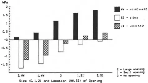
The net pressures across each wall for each of the ten leakage conditions are listed in Table 1, Figures 2 and 3 show that each of the ten cases results in an internal pressure different from the rest. Increasing the internal pressure transfers some of the cladding load from the windward wall to the other three walls. Similarly, decreasing the internal pressure transfers load from the
I three walls (under negative external pressure) to the windward wall. Note
that the differences in net pressures between wind on the long wall (Fig. 2) and wind on the short wall (Fig. 3) tend to disappear for cases with the larger opening.
I
INTERNAL PRESSURE COEFFICIENTSInternal pressure coefficients are derived by dividing the net pressure for any wall (windward, side, or leeward) in Table 1 by the reference wind pressure (1.33 kPa), and subtracting the resulting net pressure coefficient from the external one (windward, 0.78; side, -0.65; leeward, -0.26).
Simple approximations to internal pressure have been proposed. Daven- port and S U ~ N ( 1983) suggest a linear average of external pressure coefficients,
C
,
for all surface areas, weighted by the corresponding "equivalent orifice areas," described below. Newbeny and Eaton ( 1974) used the orifice equation in which flow is proportional to the square root of pressure difference. requiring an iterative solution to balance inflow and outflow.I
table 1 Net pmasums across wells at the 46th floorLong Wall Short \\'all
Wind Normal lo Windward Sides Leeward Windward Sides Leeward
Wall kPa kPa k Pa k Pa kPd kPa
Opening Area (mz) Location 3.0 Windward 0.16 -1.74 -1.22 0.21 -1.68 -1.17 1.5 Windward 0.43 -1.46 -0.95 0.58 -1.32 -0.80 NO opening 1.15 -0.74 -0.23 1.46 -0.44 0.06 1.5 One Side 1.62 -0.28 0.24 1.75 -0.14 0.37 3.0 One Side 1.80 -0.10 0.42 1.84 -0.05 0.46
692
Wind Loading and Wind EffectsT h e equivalent orifice area (A,) for the distributed leakage of a wall is
Air density r = 1.3 kg/m3 and discharge coefficient Cd = 0.60 were used to make the linear and square root approximations for comparison with results from the more detailed computer model (see Table 2). T h e three estimates of
0 5 1
-
S I D E SBLY
-
L E E W A R D2
-
~ p g o opqnlng 1-
Small aponlng2. W I. VY 0 1. SI 2.51 0
-
~a o p ~ n i n gSize (0. 1.2) and Location (WW.SI) 06 D p e n ~ n g
Fig. 2 Effect of an opening on wall praaauros: wind normal to long face of building
2 W Y
-
W I N D W A R D 1.5 0 5 1-
S I D E S IMLY
-
L E E W A R D 0. 5 -0 -0.5 -1 -1.5F 2 I
-
-
~ w g o Small op.ning opening2. w 1. VV 0 1. 51 2. S I 0
-
ua openingSlzo (0. 1.2) and Location (WW. SI) of O p m r n g
Dalgliesh-Air Infiltration
693
internal pressure coefficient. C,. are rensonablv similar for the cases of no opening and Inrge opening. However. both simple approximations overesti- mate the effects ol the small opening, a feature emphasized by the lincchart of
Fig. 4 in which each case is labelled with the internal pressure coeificient or
the computer made1 result. T h e simpler linear approximation is closer to the computer model result in all but one case.
EFFECT OF OPENING AREA
The area of the opening ranged from 1.3% to 5.2% of the area of the 43th floor wall in which it was located. However, the effectiveness of the opening
Table 2 Approximate and Detailad Estimates of C,
- - -- - -
Wind Normal to Long Wall Short Wall
Wall SQ. R o o t Linear Detailed Sq. Root Linear Detailed Opening Area (m2) Location 3.0 Windward 0.78 0.72 0.66 0.77 0.69 0.62 1.5 Windward 0.77 0.66 0.46 0.76 0.62 0.34 No opening -0.13 -0.01 -0.09 -0.47 -0.31 -0.32 1 .5 One Side -0.64 -0.56 -0.44 -0.65 -0.61 -0.54 3.0 One Side -0.65 -0.60 -0.57 -0.65 -0.63 -0.61 Linear Approx. -8-
Sqwro Root Approx.
--*--
-0. a I
-0.5' _0.+ -,,.hb -0.31 A*@ Q . 9 0.e2 0.6
Ootailod Computer Model Rosult
694
Wind Loading and Wind Effectsdepends more directly on its area relative to the equivalent orifice area of the distributed leakage. T h e sum of the A, for all four walls of the 45th floor is only about 0.25 m2.
T h e effect of relative area for wind normal to the long wall can be seen in the third column of Table 2. T h e small opening is six times the total A,. and changed the internal pressure coefficient C,, from -0.09 to -0.44 when the external pressure coefficient C,, outside the opening was -0.65, and to 0.46 when C,. was 0.78. T h e large opening is 12 times the total A, and brought C,,
from -0.09 to -0.57 when C, was -0.65, and to 0.66 when C,. was 0.78. Similar trends can be followed for the five cases of wind normal to the short wall (see last column. Table 2). A surprisingly small opening is sufficient to cause significant shifts of wind load between the windward wall and the other three walls.
CONCLUSION
A single opening the size of a large window may well have the effect of increasing the maximum cladding pressure by 60% over the case in which uniformly distributed leakage is assumed. T h e transfer of cladding load from the windward wall to the other three walls (or vice versa) is mainly the result of the wind itself altering the internal pressure, acting through the overall leakage of the building.
A computer program of the sort used in this study could be used in design to alert both the mechanical and the structural consultants to the conse- quences of deviating from a uniform distribution of leakage. T h e same computer model will predict air infiltration effects under calm or moderate wind conditions and cladding pressures for design wind speeds.
Pooling of information available to mechanical and structural consultants could benefit both contributions to design by making possible a more realis- tic assessment of internal pressure. For example, use could be made of the more detailed patterns of external pressure coefficients available to the structural designer. T h e program would have to be modified to allow com- partments in both the horizontal and the vertical directions because the flowr around a building produces large horizontal gradients in external pressure. The model used in this study gives only mean pressures, and should be extended to deal with fluctuating external pressures.
Davenport. A. G. and Surry. D.. 1983
THE ESTIMATION OF INTERNAL PRESSURES DUE TO WIND WITH APPLICATION TO CLAD. DING PRESSURES AND INFILTRATION Presented at the ASCE Structural Eng~neer~ng Conference. Houston. Texas.
. Dalgliesh-Air Infiltration
Newberry. C. W. and Eaton. K.. 1974
WIND LOADING HANDBOOK. Department of the Env~ronment. Bulld~ng Research Establ~shment. London. H.M S.O.
Sander. D. M.. 1974
FORTRAN IV PROGRAM TO CALCULATE AIR INFILTRATION IN BUILDINGS. Nat~onal Research Counc~l of Canada. D ~ v ~ s ~ o n of Bu~ld~ng Research. Computer Program No. 37. Ottawa. Shaw. C. Y.. Sander. D. M and Tamura. G T.. 1973
AIR LEAKAGE MEASUREMENTS OF THE EXTERlOR WALLS OF TALL BUILDINGS. ASHRAE Transact~ons. Vol. 79. Part 2. pp. 40-48. Also reorlnt of Nat~onal Research Counc~l of Canada. Divcslon of Bu~ld~ng Research. NRCC 1395 1.
Shaw. C. Y.. 1979
A METHOD FOR PREDICTING AIR INFILTRATION RATES FOR A TALL BUILDING SURROUNDED BY LOWER STRUCTURES OF UNIFORM HEIGHT. ASHRAE Transact~ons. Vol. 85. Part 1. PO. 72-84. Also reprlnt of Nat~onal Research Counc~l of Canada. D~vls~on of Build~ng Research. NRCC
This paper is being distributed in reprint form by the Institute for Research in Consuuction. A list of building practice and research publications available from the Institute may be obtained by writing to the Publications Section, Institute for Research in Construction, National Research Council of Canada, Ottawa, Ontario, KIA OR6.
Ce document est disuibud sous forme de tire-8-part par 1'Institut de recherche en construction. On peut obtenir unc liste des publications de 1'Institut portant sur les techniques ou Ies recherches en matiere de biitiment en ecrivmt h la Section des publications, Institut de recherche en construction, Conseil national de recherches du Canada, Ottawa (Ontario), KIA 0R6.