Design of a Passive, Shear-Based Rotary Hydraulic
Damper for Single-Axis Prosthetic Knees
The MIT Faculty has made this article openly available.
Please share
how this access benefits you. Your story matters.
Citation
Arelekatti, V. N. Murthy, Nina T. Petelina, W. Brett Johnson,
Amos G. Winter, and Matthew J. Major. “Design of a Passive,
Shear-Based Rotary Hydraulic Damper for Single-Axis Prosthetic
Knees.” Proceedings of the ASME 2018 International Design
Engineering Technical Conferences and Computers and Information
in Engineering Conference, 26-29 August, 2018, Quebec City,
Quebec, Canada, ASME, 2018. © 2018 by ASME
As Published
http://dx.doi.org/10.1115/DETC2018-85962
Publisher
American Society of Mechanical Engineers
Version
Final published version
Citable link
http://hdl.handle.net/1721.1/120009
Terms of Use
Article is made available in accordance with the publisher's
policy and may be subject to US copyright law. Please refer to the
publisher's site for terms of use.
DESIGN OF A PASSIVE, SHEAR-BASED ROTARY HYDRAULIC DAMPER FOR
SINGLE-AXIS PROSTHETIC KNEES
V. N. Murthy Arelekatti, Nina T. Petelina Global Engineering and Research Laboratory
Department of Mechanical Engineering Massachusetts Institute of Technology
Cambridge, Massachusetts 02139 Email:[email protected], [email protected]
W. Brett Johnson
Global Engineering and Research Laboratory Department of Mechanical Engineering
Massachusetts Institute of Technology Cambridge, Massachusetts 02139
Email: [email protected]
Amos G. Winter, V
Global Engineering and Research Laboratory Department of Mechanical Engineering
Massachusetts Institute of Technology Cambridge, Massachusetts 02139
Email: [email protected]
Matthew J. Major
Department of Physical Medicine and Rehabilitation Northwestern University
Chicago, Illinois 60611
Email: [email protected]
ABSTRACT
With over 30 million people worldwide in need of assistive devices, there is a great need for low-cost, high performance prosthetic technologies in the developing world. A majority of the hydraulic dampers used in prosthetic knee designs are highly specialized, expensive, require regular maintenance, and are incompatible for use with low-cost, single-axis prosthetic knees popular in developing countries. In this study, optimal damping coefficients were computed based on a theoretical analysis of gait, specifically during the transition from the stance to swing phase of human walking when a large damping torque is needed at the knee. A novel rotary hydraulic damper prototype was designed using high-viscosity silicone oil and a concentric meshing of fins for shearing the oil. The prototype was validated experimentally to provide the desired damping torque profile. For preliminary, user-centric validation of the prototype, a gait study on one above-knee amputee in India was conducted with four different damping magnitudes. Feedback from the subject validated the optimal damping torque magnitude predicted for minimizing gait deviations and for enabling able-bodied
knee kinematics. The new rotary hydraulic damper design is novel, passive, and compatible with low-cost, single-axis knee prostheses.
1 INTRODUCTION
This paper presents the analysis, design, and testing of a novel hydraulic damper for a fully passive prosthetic knee mechanism. The primary goal of this study was to create a damper design that can provide accurate control of single axis knees, allow smooth transition between stance and swing phases, and can be integrated in the popular single-axis architecture of prosthetic knees. The overarching theme of the current research is to design all the modules required to assemble an affordable, passive knee prosthesis which can enable able-bodied gait for above-knee amputees in developing countries, based on the prior work done by Narang, Arelekatti and Winter [1–8].
Proceedings of the ASME 2018 International Design Engineering Technical Conferences and Computers and Information in Engineering Conference IDETC/CIE 2018 August 26-29, 2018, Quebec City, Quebec, Canada
1.1 Motivation
There are over 30 million people worldwide in need of prosthetic and orthotic devices, according to a recent estimate by the World Health Organization [9]. Previous studies have estimated that there are over 230,000 above-knee amputees in India alone [8, 10, 11], where this research is focused. A majority of these amputations are the result of diverse factors such as poor health care, unsafe conditions of work, transport, and daily lifestyles [8, 12, 13]. A few prosthetic knee joints have been designed to meet the unique needs of amputees in the developing world. However, many of them are yet to be adopted at scale, due to limitations in the biomechanical performance, design, manufacturing processes, clinical training, and maintenance [12, 13]. Past studies have also reported that amputation results not only in 47% of the amputees having to change or losing their occupations, but also leads to economic deprivation and serious social stigma [14–16], which highlights the urgent need for high-performance, low-cost prostheses that can enable able-bodied gait, increase metabolic efficiency for the users, and mitigate socio-economic discrimination faced by amputees.
1.2 Relevant Terminology
A brief summary of the relevant terms from gait biomechanics used in this paper are laid out briefly for the uninitiated reader (Fig. 1).
1.3 Damping in the Prosthetic Knee Function
Damping in prosthetic knees is primarily required to decelerate the knee flexion during the transition from the stance phase to the swing phase. This duration is the zone between knee angle b and c of the able-bodied gait cycle (Fig. 1C). A smaller amount of damping is also required to control the knee extension in the swing phase between knee angles c and a, before the heel-strike of the next gait cycle. At knee angle b, the knee begins to flex in preparation for the swing phase. This flexion continues all the way up to the peak flexion angle c in the swing phase. In the absence of sufficient damping, the prosthetic knee can overshoot well beyond the peak flexion of the knee required for ground clearance, delaying the gait cycle duration for the amputated leg. Conversely, if the damping torque is greater than the optimal value, the knee doesn’t flex enough, which can force the amputee to employ alternative strategies to achieve ground clearance during the swing phase, such as hip-hiking, vaulting, and circumduction [19]. Such asymmetric gait patterns between the able-bodied leg and the amputated leg are undesirable as they can result in increasing energy demands [19]. Additionally, in the context of developing countries such as India, the focus on achieving able-bodied gait behavior has been shown to be one of the most important design requirements for amputees [8]. Amputees repeatedly report the need for an inconspicuous gait
to mitigate the socio-economic discrimination that they face, demanding prosthetic performance that can enable able-bodied gait kinematics [8, 11].
A wide array of prosthetic knees have been designed to provide damping control. Primarily designed for amputees in mature markets, popular knee prostheses have incorporated fluid-based (pneumatic or hydraulic) systems, which can be controlled passively, or using programmable, microprocessor-controlled actuators [20, 21]. Affordable prosthetic knee joints, designed primarily for the developing world, have incorporated passive friction brakes that provide
Knee
Angle (Flexion)
Gait Cycle (% time)
Stance Phase Swing Phase
0 10 20 30 40 50 60 70 80 90 100 60O 45O 30O 15O 0O Knee Angle (Flexion)
Gait Cycle (% time)
Stance Phase Swing Phase
0 10 20 30 40 50 60 70 80 90 100 60O 45O 30O 15O 0O
Knee angle (flexion)
a
Flexion Extension Knee flexion angleC
A
a b c aB
Trunk Hip joint Knee joint Ankle joint Upper leg Lower leg FootFIGURE 1. A. The knee flexion angle is defined as the relative angle
between the upper leg segment and the lower leg segment. The direction of knee extension is opposite to that of flexion. B. Two-dimensional, four-segment link structure to model the prosthetic leg. C. The human gait cycle of each leg is divided into the stance phase, followed by the swing phase when the foot leaves contact with the ground for clearance. The graph shows the normative knee angle kinematics through the gait cycle (red curve), along with the standard deviation shown in grey band [17, 18]. The illustration below the horizontal axis shows the corresponding leg trajectory through the gait cycle.
fixed resistance during flexion [22]. The implementation of friction brakes has been achieved through the use of bolts with adjustable tension. This technique is simple and cost effective but presents many practical challenges. The friction torque changes with continued usage due to wear and changing environmental conditions, such as humidity or rain [4]. Moreover, friction brakes provide constant resistance, which makes them unresponsive to changes in cadence [23]. Fluid-based dampers offer smooth, cadence-based resistance. However, fluid-based dampers are more expensive, bulky, and require periodic maintenance to prevent oil-leaks and they have not been tested in the harsh outdoor conditions of developing countries such as India [22]. In order to address the limitations of traditional fluid-based dampers, this study presents the computational gait analysis, design and testing of a novel rotary hydraulic damper, which is compatible for use in low-cost, single-axis prosthetic knees. The prosthetic knee used in this study was developed by Arelekatti and Winter [4]. However, the design and implementation of the damper is relevant for all single-axis designs of prosthetic knees.
2 Methodology
2.1 Computational Modeling and Analysis of Damping
As the first step of this study, the target knee torque required to replicate able-bodied leg kinematics in above-knee amputees was identified. The kinematic data required for the analysis was obtained from an experimental study of a below-knee amputee using a fully passive U-spring foot designed by Prost [24]. In that study, the U-spring foot was mechanically characterized, theoretically optimized, and experimentally validated to provide the closest possible replication of able-bodied leg kinematics for a below-knee amputee.
To perform the target knee torque computation, a two-dimensional, four-segment segment model of the prosthetic leg was designed (Fig. 1B) and inverse dynamics performed according to the methods presented by Narang et al. [1]. Experimental kinematic data from a unilateral below-knee amputee walking with a fully characterized U-spring foot was used as an input for inverse dynamics [24]. Since the masses of prosthetic leg segments are typically lower than those of able-bodied segments [25], the knee torque was computed for varying inertial parameters of the upper leg (the segment between the hip and the knee), the lower leg (the segment between the knee and ankle), and the prosthetic foot (Fig. 1B). The masses of the upper-leg, the lower-leg, and the prosthetic foot were varied between 25% and 100% of corresponding able-bodied values.
In the prosthetic leg model, a rotary hydraulic damper was modeled to engage during the transition from the stance phase to swing phase, specifically in the zone between knee angle b and c of the gait cycle (Fig. 1B). The corresponding zone for
0 1 2 3 4
Damping Coefficient (N*m/(rad/s)) 0 0.2 0.4 0.6 0.8 1 R 2
R2 for varying values of lower-leg mass 75% 50% 25% 100%
0 20 40 60 80 100
Gait cycle (% time) -0.4 -0.2 0 0.2 Knee Torque (N*m/kg) 0 20 40 60 80 100
Gait cycle (% time) 0 10 20 30 40 50 60 70
Knee Angle (degrees)
Tdamp
Target Knee Torque
A
B
C
FIGURE 2. A. Knee angle kinematics data for a below-knee amputee
using the passive, U-spring foot [24]. The damping zone of interest is highlighted. B. Target knee torque for replication was computed by inverse dynamics and a best-fit analysis was done to estimate the
optimal damping torque in the damping zone, Tdamp. C. The damping
coefficients were computed for four mass values of the lower-leg, expressed as percentage fraction of the able-bodied mass of the lower leg. The optimal damping coefficient for each mass was chosen based
on the maximum R2value computed over the damping zone.
the kinematic data used for the analysis is highlighted in Fig. 2A (hereby referred to as the “damping zone”). The rotary hydraulic damper was modeled as an ideal, first-order, shear-based viscous damping element, formulated mathematically as follows:
where Tdampis the damping torque, which is the product of
the measured angular velocity of the knee over the damping zone, ˙
θknee, and B, the damping coefficient.
A simple optimization routine was set up to compute the best-fit damping torque profile over the damping zone. In order to estimate the optimal damping coefficient, the damping torque Tdamp profiles were computed for a range of damping coefficients. The damping torque profile with highest coefficient of determination (R2) with reference to the target damping torque was selected and the corresponding damping coefficient identified as the optimal case (Fig. 2B).
This optimization routine was set up for a range of combination of mass properties of the upper leg, lower leg, and foot of the prosthetic leg. For any specific combination of the mass properties of the prosthetic leg, the optimal damping coefficient, Boptimal, could be computed. For instance, for an
amputee with total body weight 75 kg, 100% upper leg mass (of able-bodied value), 50% lower leg mass (of able-bodied value), and 100% mass of the U-spring foot, Boptimal = 1.5 N-m/(rad/s)
(Fig. 2C).
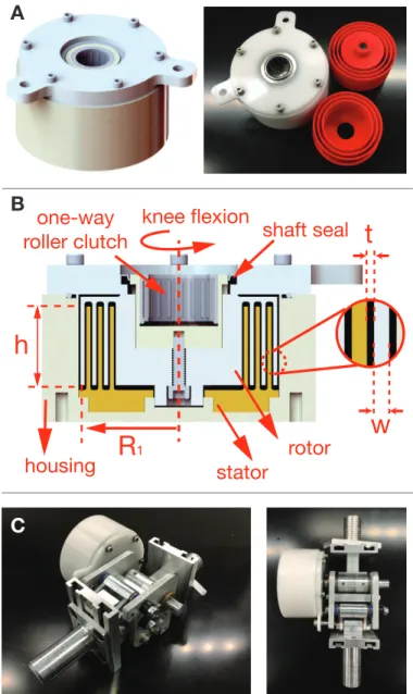
2.2 The Design
The detailed construction of the damper prototype is illustrated in Fig. 3. The damping torque in the assembly is generated by shearing a highly viscous liquid between the stator and the rotor. The rotor is coupled coaxially to the rotating shaft from the prosthetic knee, which provides the rotary motion as the knee flexes. The stator is coupled to the housing, which is static and rigidly coupled to the prosthetic knee assembly. The stator and the rotor have concentric thin-wall fins that mesh into each other coaxially about the knee axis, leaving a small gap with liquid between the neighboring fins of the stator and the rotor (Fig. 3B). The resulting damping torque due to the shearing of viscous liquid between the neighboring stator-rotor fins is quantified by the following relationship, derived by integrating the viscous shear stress caused by couette flow of the liquid along the circumferential area of the fin walls [26]:
Bf in= Tdamp ˙ θknee =2π µh t (R 3 1+ (R1− w)3) (2)
where Bf inis the resultant damping coefficient, Tdampis the viscous damping torque, ˙θkneeis the angular velocity of the knee
joint, µ is the dynamic viscosity of the fluid, h is the height of the fins, t is the thickness of the gap between the stator fin and rotor fin , R1is the radius of the exterior surface of the fin, and w
is the thickness of the fin wall. These variables are annotated in Fig. 3B.
The total damping torque for multiple fins, as illustrated in Fig. 3, is a summation:
w
t
knee flexion
R
1shaft seal
h
one-way
roller clutch
housing
stator
rotor
A
B
C
FIGURE 3. A. Damper Prototype assembly: CAD and photograph of
the final assembly. The stator and rotor fins were 3D printed in red ABS plastic. B. Cross sectional view of the damper prototype, silicone oil is entrapped between the rotor and stator fins. C. The damper was mounted coaxially to the prosthetic knee assembly, as shown. The housing cap was bolted on to the side of the prosthetic knee structure.
Btotal=Tdamp ˙ θknee = n
∑
i=1 2π µh t ((R1−(i−1)D) 3+(R 1−w−(i−1)D)3) (3) D= 2(w + t) (4)where n is the total number of fins on either the stator or the rotor and D is the step distance to the next set of interacting fins, n= 3 in Fig. 3B.
The housing and the housing cap of the damper prototype were machined out of Delrin. The stator and rotor fins were 3D printed using ABS plastic (Fig. 3A). The rotor was coupled to a one-way roller clutch, which in turn was coupled to the rotating knee shaft (Fig. 3B). The one-way roller clutch ensures that damping is enabled only within the damping zone. During knee extension, there was no damping and the knee shaft rotated freely within the roller clutch. The viscous fluid used in the damper consisted of Polydimethylsiloxane, a silicone oil with a very high kinematic viscosity of 100,000 centistokes. The dynamic viscosity of the oil is 100 Pa-s. For comparison, the dynamic viscosity of water is 1 mPa-s. The oil displays a characteristic non-newtonian behavior, with the apparent reduction in viscosity as the shear rate increases (known as shear thinning). To account for this change in viscosity, the damping torque calculation was adjusted based on the shear-thinning data provided by the manufacturer [27] . In order to seal the fluid in the damper, an O-ring as well as a rotary shaft seal were incorporated between the rotating assembly and the stationary housing (Fig. 3B).
DC Motor
Coupler
Damper
Load Cell
FIGURE 4. Experimental setup for mechanical characterization of the
damper prototype. The housing of the damper prototype is connected to a load cell through a lever arm to measure the torque, and the shaft is driven by the velocity-controlled DC motor.
2.3 Mechanical Testing
A test setup was built for experimental characterization of the prototype performance before testing the prosthetic knee assembly on an above-knee amputee (Fig. 4). A velocity-controlled DC motor (VexRobotics) was used to apply a linearly increasing velocity profile to the damper and a magnetic encoder was used to record and control the angular velocity. A load cell (Omega Engineering LC101-250) measured the force experienced by the damper at a fixed lever length. The velocity control and the data collection was controlled on a Visual Basic platform supported by VexRobotics.
In order to measure the torque velocity relationship, the motor applied a linearly increasing velocity profile up to the maximum angular velocity of 6 rad/sec. This limit was chosen based on the largest knee angular velocities measured in the able-bodied human gait [17]. The experimental setup was validated with two commercially available viscous dampers (ACE controls FDT-57 and FDT-63 [28]). The experimentally measured values matched the values provided by the data sheet for both the dampers.
2.4 Preliminary Clinical Study in India
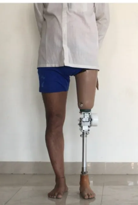
To further validate the results of the design and computational modeling, a preliminary, qualitative study was conducted at the Jaipur-Foot clinic in Jaipur, India with one above-knee amputee [29]. The MIT Committee on the Use of Humans as Experimental Subjects approved the experiment protocol. At the time of testing, the subject had been using a simple, single-axis knee for daily use, which was designed and distributed by the Jaipur-foot organization.
The main goal of this study was to receive qualitative feedback on the different damping conditions and observe whether there are visible differences in the gait for different cases. The subject was tested with four different cases of damping coefficients, with zero, low, optimal, and high magnitudes. The relevant human body parameters of the subject (Table 1) were used for calculating the damper coefficients, as previously discussed in the computational modeling and analysis section. The low, optimal, and high magnitudes of the damping coefficients for the subject were estimated as Blow
Gender Male
Weight (kg) 75
Knee-axis to the ground height (cm) 49 Foot size (cm) 28
TABLE 1. Body parameters of the subject (Fig. 5), which were used
FIGURE 5. Subject wearing the knee prosthesis with the damper
prototype. The knee prosthesis was attached to the socket, which
interfaces with the residual limb and the pylon, which interfaces with the prosthetic foot.
= 0.8 N-m/(rad/s), Boptimal = 1.5 N-m/(rad/s), and Bhigh = 2.2
N-m/(rad/s), respectively. The low and high coefficients were chosen to be 50% lower and higher than the optimal value. Three different damper prototypes were constructed, with a different number of interacting fins, n, as discussed in the previous section (Equation 3). The knee prosthesis used in the study was a single-axis prosthetic knee designed by Arelekatti et al. [4]. A standard single-part prosthetic foot designed by the Jaipur-foot organization was used [29], along with the standard pylon and socket assembly (Fig. 5).
The testing protocol began by a fitment session of the prosthetic knee by a trained prosthetist (Fig. 5). After an acclimatization period, the subject was asked to walk for 10 minutes with each of the four different damping conditions. Starting without a damper, the dampers were tested in the order of increasing damping value (low, optimal, and high). The subject wasn’t told about which damper was being tested in order to evaluate whether it was possible for the subject to detect the difference between the three different dampers. Qualitative feedback from the subject and the prosthetist was collected after each trial. Each trial was video-recorded with an iPhone camera.
3 RESULTS
3.1 Mechanical Testing
The results of mechanical testing of each of the three dampers (low, optimal, and high) are shown in Fig. 6. The
0 1 2 3 4 5 6
Angular Velocity (rad/s)
0 5 10 15
Damping Torque (N*m)
Low damper (computed): 0.8 Nm/(rad/s) Optimal damper (computed): 1.5 Nm/(rad/s) High damper (computed): 2.2 Nm/(rad/s) Low damper (experiment)
Optimal damper (experiment) High damper (experiment)
FIGURE 6. The three dampers were mechanically tested over a
linearly increasing velocity range
theoretically calculated values of damping torque in the design (Equation 3) were found to be larger than the experimental measurements by over 20% at the highest angular velocity (6 rad/s). However, at lower velocities up to 3 rad/s, there was less than 10% difference. One of the possible causes of this behavior was the porous nature of the 3D printed fin structures. The pores could provide an alternative flow path for the Silicone oil due to high shearing forces. In addition, the dampers were filled with silicone oil by hand. In the absence of a concealed vacuum chamber, the silicone oil absorbs ambient air leading to bubble entrapments which can reduce the effective viscosity of the fluid. Additionally, because of the linearly increasing angular velocity profile, the oil may have warmed up, altering it’s viscosity. Despite the error, the theoretical calculation was found to be an extremely useful design tool to size the damper prototype before empirical characterization through mechanical testing.
3.2 Preliminary Clinical Study in India
After an acclimatization period of 10 minutes, the subject was able to walk with the knee prosthesis comfortably (Fig. 7A). The subject was able to identify the three different damping values as low, medium, and high without explicit suggestions or prompts.
There was an observable difference in the peak knee-flexion angle that was observed between the four different test cases (Fig. 7B-E). The high damping case prevented proper toe clearance, as the subject was unable to flex the knee far enough to clear the ground. Moreover, the high damping case was the only case where the subject reported the need to concentrate and exert extra muscular effort to ensure smooth stance to swing transition. The subject also reported negligible change between
No Damper, Peak knee flexion angle = 72°
A
B
C
D
E
Low Damping, 60° Optimal Damping, 44° High Damping, 36°
FIGURE 7. A. The subject walking comfortably after acclimatization, snapshots through a full gait cycle are shown (read left to right). There is no
damping module attached. B-E. The approximate values of peak flexion angle through the swing phase were calculated using the image processing toolbox on MATLAB.
the no-damping case and the low-damping case, as there was little resistance on offer in the damper. The optimal case damper was perceived by the subject as the most comfortable one, offering smooth transition and minimal conscious effort to use it. This confirmed the predicted optimal case damper as the best of the three damping coefficients. However, a full clinical gait analysis with motion capture cameras and ground reaction force plates is yet to be carried out, which will provide more accurate information about the kinematic performance under different damping conditions.
4 DISCUSSION
4.1 Comparison with Traditional Fluid Dampers The most common fluid dampers used in prosthetic knees are linear hydraulic cylinders, which are made of a piston and two chambers [20]. The damping force is the result of pressurized flow of a viscous fluid from one chamber to the
other through a small orifice, usually adjustable in diameter. This necessitates the use of a hydraulic accumulator, which can accommodate the changes in volume to keep the fluid inside completely pressurized. These features have tight tolerances, requiring expensive manufacturing processes. In the absence of high-quality manufacturing, the seal between the two chambers can break down due to repeated sliding, leading to frequent leaks and seal failures. Additionally, the damping force is proportional to the square of the piston velocity, leading to a non-linear dependence which can be uncomfortable for amputees with sudden cadence changes. The linear hydraulic cylinders also require an additional linkage between the rotating elements. The rotary, shear-based architecture of hydraulic dampers overcomes these challenges on most fronts. It is very simple to integrate within the knee system as it can be mounted coaxially. It provides a predictable, linear dependence to gait cadence and consists of only one dynamic seal on a shaft, which is rotating (and not sliding). The seal can be mounted close to the axis
to reduce the friction torque on the seals, mitigating the seal wear. They can also be made very compact by the use of high-viscosity liquids, such as silicone oils, which are very safe to use and are available worldwide at competitive prices due to their widespread use in cosmetics and industry.
4.2 Using Kinematic Data Input from Below-knee Amputees
The behavior of the foot prosthesis should be accounted towards any attempt to replicate able-bodied kinematics for above-knee amputees [1]. Passive prosthetic feet cannot enable the ankle plantar-flexion required during the transition from stance to swing [17], altering the kinematics of below-knee amputees. Therefore, this study used the experimental kinematic data from a study that implemented a fully characterized passive foot to reduce the kinematic error in the lower-leg trajectory of below-knee amputees. We hypothesize that using a fully optimized passive foot in association with an optimized knee module will reduce the overall trajectory error of the lower leg. The hypothesis may be novel, but needs to be supported by further evidence through experimental investigations [24].
4.3 Limitations and Future Work
A complete quantitative, clinical gait-analysis of multiple subjects would be required to quantify the performance of the different damping magnitudes empirically. This would involve collecting marker data using motion capture systems along with ground reaction force data. This experiment is ongoing and the results are expected to be more conclusive than the results of qualitative user-testing presented in this study. The qualitative clinical study was done in conjunction with a passive foot used by Jaipur-foot, which was not characterized in the analysis of this study. In future, a fully optimized leg assembly with an optimized prosthetic knee and an optimized prosthetic foot such as the U-spring foot would be relevant. Furthermore, this study used kinematic data only from one subject and the user-centric study also involved only one subject. Data from a large sample of subjects and testing on an equally large sample of subjects spanning different body parameters would be necessary to conclusively establish insights, which could be used by other prosthesis designers and researchers.
The rotor and stator fins in the prototype were made of 3D printed plastic (ABS), which is porous and has low strength properties. In the future, these parts could be substituted with stronger materials such as molded plastic. The resulting addition in strength could aid in the making the design more compact by the addition of more fins in the same amount of space. Streamlining the liquid filling process in the damper with suction would need to be devised to ensure that there is minimal bubble entrapment. Additionally, a detailed cost and manufacturing analysis would be necessary to clarify the advantage of the
rotary, shear-based hydraulic damping architecture. Local manufacturing in developing countries will also need to be considered for a complete comparison in terms of affordability of damping products in a global market.
ACKNOWLEDGEMENT
We would like to acknowledge Dr. Pooja Mukul and the rest of the staff at Bhagwan Mahaveer Viklang Sahayata Samiti (BMVSS, a.k.a., the Jaipur-Foot Organization, Jaipur, India) for their partnership in our work. Funding for this study was provided by the the Tata Center for Technology and Design at MIT, the National Science Foundation Graduate CAREER Grant (no. 1653758), and the Indo-US NIH collaborative program grant on affordable medical devices (no. 9208498).
REFERENCES
[1] Narang, Y. S., Arelekatti, V. M., and Winter, A. G., 2016. “The effects of prosthesis inertial properties on prosthetic knee moment and hip energetics required to achieve able-bodied kinematics”. IEEE Transactions on Neural Systems and Rehabilitation Engineering, 24(7), pp. 754–763.
[2] Narang, Y. S., Arelekatti, V. M., and Winter, A. G., 2016. “The effects of the inertial properties of above-knee prostheses on optimal stiffness, damping, and engagement parameters of passive prosthetic knees”. Journal of Biomechanical Engineering, 138(12), p. 121002.
[3] Arelekatti, V. N. M., and Winter V, A. G., 2016. “Design of a fully passive prosthetic knee mechanism for transfemoral amputees in india”. Journal of Mechanisms and Robotics. In Press.
[4] Berringer, M. A., Boehmcke, P. J., Fischman, J. Z., Huang, A. Y., Joh, Y., Warner, J. C., Arelekatti, V. N. M., Major, M. J., and Winter, A. G., 2017. “Modular Design of a Passive, Low-Cost Prosthetic Knee Mechanism to Enable Able-Bodied Kinematics for Users With Transfemoral Amputation”. In ASME 2017 International Design Engineering Technical Conferences and Computers and Information in Engineering Conference, American Society of Mechanical Engineers, pp. V05BT08A028—-V05BT08A028.
[5] Arelekatti, V. M., and Winter, A. G., 2015. “Design of mechanism and preliminary field validation of low-cost, passive prosthetic knee for users with transfemoral amputation in india”. In ASME 2015 International Design Engineering Technical Conferences and Computers and Information in Engineering Conference, American Society of Mechanical Engineers, pp. V05AT08A043–V05AT08A043.
of a fully passive prosthetic knee mechanism for transfemoral amputees in india”. In Rehabilitation Robotics (ICORR), 2015 IEEE International Conference on, IEEE, pp. 350–356.
[7] Cavuto, M. L., Chun, M., Kelsall, N., Baranov, K., Durgin, K., Zhou, M., Arelekatti, V. M., and Winter, A. G., 2016. “Design of mechanism and preliminary field validation of low-cost transfemoral rotator for use in the developing world”. In ASME 2016 International Design Engineering Technical Conferences and Computers and Information in Engineering Conference, American Society of Mechanical Engineers, pp. V05AT07A035–V05AT07A035.
[8] Narang, Y. S., 2013. “Identification of Design Requirements for a High-Performance , Low-Cost , Passive Prosthetic Knee Through User Analysis and Dynamic Simulation”. Master’s thesis, Massachusetts Institute of Technology, Cambridge MA.
[9] World Health Organization, 2011. World Report on Disability. Tech. rep., World Health Organization.
[10] Narang, I. C., Mathur, B. P., Singh, P., and Jape, V. S., 1984. “Functional capabilities of lower limb amputees.”. Prosthetics and orthotics international, 8(1), Apr., pp. 43–51.
[11] Hamner, S. R., Narayan, V. G., and Donaldson, K. M., 2013. “Designing for Scale: Development of the ReMotion Knee for Global Emerging Markets”. Annals of Biomedical Engineering, 41(9), Sept., pp. 1851–9.
[12] Cummings, D., 1996. “Prosthetics in the developing world: a review of the literature.”. Prosthetics and orthotics international, 20(1), Apr., pp. 51–60.
[13] Andrysek, J., 2010. “Lower-limb prosthetic technologies in the developing world: a review of literature from 1994-2010”. Prosthetics and Orthotics International, 34(4), pp. 378–398.
[14] Mohan, D., 1967. “A Report on Amputees in India”. Orthotics and Prosthetics, 40(1), pp. 16–32.
[15] Horgan, O., and MacLachlan, M., 2004. “Psychosocial adjustment to lower-limb amputation: a review”. Disability and rehabilitation, 26(14-15), pp. 837–850.
[16] Rybarczyk, B., Nyenhuis, D. L., Nicholas, J. J., Cash, S. M., and Kaiser, J., 1995. “Body image, perceived social stigma, and the prediction of psychosocial adjustment to leg amputation.”. Rehabilitation psychology, 40(2), p. 95. [17] Winter, D. A., 2009. Biomechanics and Motor Control of
Human Movement, 4th ed. John Wiley & Sons, Inc. [18] Baker, R., 2013. Measuring walking: a handbook of
clinical gait analysis. Mac Keith Press.
[19] Smith, D. G., Michael, J. W., Bowker, J. H., of Orthopaedic Surgeons, A. A., et al., 2004. Atlas of amputations and limb deficiencies: surgical, prosthetic, and rehabilitation principles, Vol. 3. American Academy of Orthopaedic Surgeons Rosemont, IL.
[20] Gard, S. A., 2016. The Influence of Prosthetic Knee Joints on Gait. Springer International Publishing, Cham, pp. 1–24.
[21] Wyss, D., 2012. “Evaluation and design of a globally applicable rear-locking prosthetic knee mechanism”. Master’s thesis, University of Toronto.
[22] Furse, A., Cleghorn, W., and Andrysek, J., 2011. “Development of a low-technology prosthetic swing-phase mechanism”. Journal of Medical and Biological Engineering, 31(2), pp. 145–150.
[23] Radcliffe, C. W., 1977. “The knud jansen lecture: above-knee prosthetics”. Prosthetics and Orthotics International, 1(3), pp. 146–160.
[24] Prost, V., 2017. “Experimental Validation of the Lower Leg Trajectory Error, an Optimization Metric for Prosthetic Feet”. Master’s thesis, Massachusetts Institute of Technology.
[25] Czerniecki, J. M., Gitter, A., and Weaver, K., 1994. “Effect of alterations in prosthetic shank mass on the metabolic costs of ambulation in above-knee amputees”. American Journal of Physical Medicine & Rehabilitation, 73, pp. 348–352.
[26] White, F. M., 2016. Fluid mechanics, 8th ed. McGraw-Hill. [27] Silicone oils and lubricants from clearco. http://www.clearcoproducts.com/. (Accessed on 03/12/2018).
[28] Rotary dampers - motion control - products - ace controls inc. http://www.acecontrols.com/. (Accessed on 03/12/2018).
[29] Bhagwan Mahaveer Viklang Sahayata Samiti, 2014. What We Do: Above Knee Prosthesis. http://jaipurfoot.org/ (Accessed 5/19/14).

![FIGURE 2. A. Knee angle kinematics data for a below-knee amputee using the passive, U-spring foot [24]](https://thumb-eu.123doks.com/thumbv2/123doknet/14685106.560053/4.918.527.813.117.690/figure-knee-angle-kinematics-amputee-using-passive-spring.webp)