IAEA HumAN HEAltH SErIES
158
0
0
Texte intégral
(2) IAEA HUMAN HEALTH SERIES PUBLICATIONS The mandate of the IAEA human health programme originates from Article II of its Statute, which states that the “Agency shall seek to accelerate and enlarge the contribution of atomic energy to peace, health and prosperity throughout the world”. The main objective of the human health programme is to enhance the capabilities of IAEA Member States in addressing issues related to the prevention, diagnosis and treatment of health problems through the development and application of nuclear techniques, within a framework of quality assurance. Publications in the IAEA Human Health Series provide information in the areas of: radiation medicine, including diagnostic radiology, diagnostic and therapeutic nuclear medicine, and radiation therapy; dosimetry and medical radiation physics; and stable isotope techniques and other nuclear applications in nutrition. The publications have a broad readership and are aimed at medical practitioners, researchers and other professionals. International experts assist the IAEA Secretariat in drafting and reviewing these publications. Some of the publications in this series may also be endorsed or cosponsored by international organizations and professional societies active in the relevant fields. There are two categories of publications in this series: IAEA HUMAN HEALTH SERIES Publications in this category present analyses or provide information of an advisory nature, for example guidelines, codes and standards of practice, and quality assurance manuals. Monographs and high level educational material, such as graduate texts, are also published in this series. IAEA HUMAN HEALTH REPORTS Human Health Reports complement information published in the IAEA Human Health Series in areas of radiation medicine, dosimetry and medical radiation physics, and nutrition. These publications include reports of technical meetings, the results of IAEA coordinated research projects, interim reports on IAEA projects, and educational material compiled for IAEA training courses dealing with human health related subjects. In some cases, these reports may provide supporting material relating to publications issued in the IAEA Human Health Series. All of these publications can be downloaded cost free from the IAEA web site: http://www.iaea.org/Publications/index.html Further information is available from: Sales and Distribution Unit International Atomic Energy Agency Vienna International Centre PO Box 100 1400 Vienna, Austria Readers are invited to provide their impressions on these publications. Information may be provided via the IAEA web site, by mail at the address given above, or by email to: Official.Mail@iaea.org..
(3) QUALITY ASSURANCE PROGRAMME FOR SCREEN FILM MAMMOGRAPHY.
(4) The following States are Members of the International Atomic Energy Agency: AFGHANISTAN ALBANIA ALGERIA ANGOLA ARGENTINA ARMENIA AUSTRALIA AUSTRIA AZERBAIJAN BAHRAIN BANGLADESH BELARUS BELGIUM BELIZE BENIN BOLIVIA BOSNIA AND HERZEGOVINA BOTSWANA BRAZIL BULGARIA BURKINA FASO BURUNDI CAMEROON CANADA CENTRAL AFRICAN REPUBLIC CHAD CHILE CHINA COLOMBIA CONGO COSTA RICA CÔTE D’IVOIRE CROATIA CUBA CYPRUS CZECH REPUBLIC DEMOCRATIC REPUBLIC OF THE CONGO DENMARK DOMINICAN REPUBLIC ECUADOR EGYPT EL SALVADOR ERITREA ESTONIA ETHIOPIA FINLAND FRANCE GABON GEORGIA GERMANY. GHANA GREECE GUATEMALA HAITI HOLY SEE HONDURAS HUNGARY ICELAND INDIA INDONESIA IRAN, ISLAMIC REPUBLIC OF IRAQ IRELAND ISRAEL ITALY JAMAICA JAPAN JORDAN KAZAKHSTAN KENYA KOREA, REPUBLIC OF KUWAIT KYRGYZSTAN LATVIA LEBANON LESOTHO LIBERIA LIBYAN ARAB JAMAHIRIYA LIECHTENSTEIN LITHUANIA LUXEMBOURG MADAGASCAR MALAWI MALAYSIA MALI MALTA MARSHALL ISLANDS MAURITANIA MAURITIUS MEXICO MONACO MONGOLIA MONTENEGRO MOROCCO MOZAMBIQUE MYANMAR NAMIBIA NEPAL NETHERLANDS NEW ZEALAND NICARAGUA NIGER. NIGERIA NORWAY OMAN PAKISTAN PALAU PANAMA PARAGUAY PERU PHILIPPINES POLAND PORTUGAL QATAR REPUBLIC OF MOLDOVA ROMANIA RUSSIAN FEDERATION SAUDI ARABIA SENEGAL SERBIA SEYCHELLES SIERRA LEONE SINGAPORE SLOVAKIA SLOVENIA SOUTH AFRICA SPAIN SRI LANKA SUDAN SWEDEN SWITZERLAND SYRIAN ARAB REPUBLIC TAJIKISTAN THAILAND THE FORMER YUGOSLAV REPUBLIC OF MACEDONIA TUNISIA TURKEY UGANDA UKRAINE UNITED ARAB EMIRATES UNITED KINGDOM OF GREAT BRITAIN AND NORTHERN IRELAND UNITED REPUBLIC OF TANZANIA UNITED STATES OF AMERICA URUGUAY UZBEKISTAN VENEZUELA VIETNAM YEMEN ZAMBIA ZIMBABWE. The Agency’s Statute was approved on 23 October 1956 by the Conference on the Statute of the IAEA held at United Nations Headquarters, New York; it entered into force on 29 July 1957. The Headquarters of the Agency are situated in Vienna. Its principal objective is “to accelerate and enlarge the contribution of atomic energy to peace, health and prosperity throughout the world’’..
(5) IAEA HUMAN HEALTH SERIES No. 2. QUALITY ASSURANCE PROGRAMME FOR SCREEN FILM MAMMOGRAPHY. INTERNATIONAL ATOMIC ENERGY AGENCY VIENNA, 2009.
(6) COPYRIGHT NOTICE All IAEA scientific and technical publications are protected by the terms of the Universal Copyright Convention as adopted in 1952 (Berne) and as revised in 1972 (Paris). The copyright has since been extended by the World Intellectual Property Organization (Geneva) to include electronic and virtual intellectual property. Permission to use whole or parts of texts contained in IAEA publications in printed or electronic form must be obtained and is usually subject to royalty agreements. Proposals for non-commercial reproductions and translations are welcomed and considered on a case-by-case basis. Enquiries should be addressed to the IAEA Publishing Section at: Sales and Promotion, Publishing Section International Atomic Energy Agency Vienna International Centre PO Box 100 1400 Vienna, Austria fax: +43 1 2600 29302 tel.: +43 1 2600 22417 email: sales.publications@iaea.org http://www.iaea.org/books. © IAEA, 2009 Printed by the IAEA in Austria October 2009 STI/PUB/1381. IAEA Library Cataloguing in Publication Data Quality assurance programme for screen film mammography. — Vienna : International Atomic Energy Agency, 2009. p. ; 29 cm. — (IAEA human health series, ISSN 2075–3772 ; no. 2) STI/PUB/1381 ISBN 978–92–0–101609–6 Includes bibliographical references. 1. Breast — Radiography — Quality control. 2. Breast — Cancer — Diagnosis — Quality control. I. International Atomic Energy Agency. II. Series. IAEAL. 09–00592.
(7) FOREWORD The application of radiation in human health, for both the diagnosis and treatment of disease, is an important component of the work of the IAEA. In the area of diagnostic radiology, this work is focused on quality assurance methods to both the promotion of the effective use of radiation for diagnostic outcome, through achieving and maintaining appropriate image quality, and also on dose determination to allow the monitoring and reduction of dose to the patient. In response to heightened awareness of the importance of patient dose contributed by radiology procedures, the IAEA published Dosimetry in Diagnostic Radiology: An International Code of Practice (Technical Reports Series No. 457) in 2007, to form a basis for patient dose determination for the Member States. Further to this, it is recognized that for complex diagnostic procedures, such as mammography, a detailed guidance document is required to give the professionals in the clinical centre the knowledge necessary to assess the patient dose, as well as to ensure that the procedure gives the maximal patient benefit possible. It is well documented that without the implementation of a quality culture and a systematic quality assurance programme with appropriate education, the detection of breast cancer cannot be made at an early enough stage to allow effective curative treatment to be undertaken. Currently there are a number of established quality assurance protocols in mammography from national and regional institutions, however, many of these protocols are distinctive and so a harmonized approach is required. This will allow the Member States to facilitate quality assurance in mammography in a standardized way which will also facilitate the introduction of national quality assurance programmes that are needed to underpin effective population screening programmes for breast cancer. Development of a quality assurance document for screen film mammography was started in 2005 with the appointment of a drafting committee of international experts. The current publication is endorsed by the European Federation of Organisations for Medical Physics and the Asia-Oceania Federation of Organizations of Medical Physics. The IAEA acknowledges the special contribution of the drafting committee chaired by M. Yaffe (Canada), with M. Chevalier (Spain), J.C. Heggie (Australia), P. Mora (Costa Rica) and K. Young (United Kingdom), and the American College of Radiology (ACR), which gave permission for the use of material from its Quality Assurance Manual. PAHO involvement is also acknowledged. The IAEA officers responsible for this publication were I.D. McLean (Division of Human Health), F. Pernička (Division of Human Health) and P. Ortiz López (Division of Radiation, Transport and Waste Safety)..
(8) EDITORIAL NOTE Although great care has been taken to maintain the accuracy of information contained in this publication, neither the IAEA nor its Member States assume any responsibility for consequences which may arise from its use. The use of particular designations of countries or territories does not imply any judgement by the publisher, the IAEA, as to the legal status of such countries or territories, of their authorities and institutions or of the delimitation of their boundaries. The mention of names of specific companies or products (whether or not indicated as registered) does not imply any intention to infringe proprietary rights, nor should it be construed as an endorsement or recommendation on the part of the IAEA..
(9) CONTENTS 1.. 2.. 3.. 4.. INTRODUCTION . . . . . . . . . . . . . . . . . . . . . . . . . . . . . . . . . . . . . . . . . . . . . . . . . . . . . . . . . . . . . . . . . . . . .. 1. 1.1. Why high quality in mammography is necessary . . . . . . . . . . . . . . . . . . . . . . . . . . . . . . . . . . . . . . . . 1.2. Purpose . . . . . . . . . . . . . . . . . . . . . . . . . . . . . . . . . . . . . . . . . . . . . . . . . . . . . . . . . . . . . . . . . . . . . . . . . . 1.3. Philosophy . . . . . . . . . . . . . . . . . . . . . . . . . . . . . . . . . . . . . . . . . . . . . . . . . . . . . . . . . . . . . . . . . . . . . . .. 1 1 2. ELEMENTS OF HIGH QUALITY MAMMOGRAPHY . . . . . . . . . . . . . . . . . . . . . . . . . . . . . . . . . . .. 3. 2.1. Personnel . . . . . . . . . . . . . . . . . . . . . . . . . . . . . . . . . . . . . . . . . . . . . . . . . . . . . . . . . . . . . . . . . . . . . . . . 2.2. Equipment . . . . . . . . . . . . . . . . . . . . . . . . . . . . . . . . . . . . . . . . . . . . . . . . . . . . . . . . . . . . . . . . . . . . . . . 2.2.1. Mammography unit . . . . . . . . . . . . . . . . . . . . . . . . . . . . . . . . . . . . . . . . . . . . . . . . . . . . . . . . . 2.2.2. Image receptor system . . . . . . . . . . . . . . . . . . . . . . . . . . . . . . . . . . . . . . . . . . . . . . . . . . . . . . . 2.2.3. Processing . . . . . . . . . . . . . . . . . . . . . . . . . . . . . . . . . . . . . . . . . . . . . . . . . . . . . . . . . . . . . . . . . . 2.2.4. Viewing conditions . . . . . . . . . . . . . . . . . . . . . . . . . . . . . . . . . . . . . . . . . . . . . . . . . . . . . . . . . . 2.2.5. Quality assurance . . . . . . . . . . . . . . . . . . . . . . . . . . . . . . . . . . . . . . . . . . . . . . . . . . . . . . . . . . . 2.2.6. Regular maintenance. . . . . . . . . . . . . . . . . . . . . . . . . . . . . . . . . . . . . . . . . . . . . . . . . . . . . . . . .. 3 3 3 3 4 4 4 4. BASIC PRINCIPLES OF QUALITY ASSURANCE IN MAMMOGRAPHY . . . . . . . . . . . . . . . . .. 5. 3.1. Quality assurance activities . . . . . . . . . . . . . . . . . . . . . . . . . . . . . . . . . . . . . . . . . . . . . . . . . . . . . . . . . 3.2. Roles and responsibilities . . . . . . . . . . . . . . . . . . . . . . . . . . . . . . . . . . . . . . . . . . . . . . . . . . . . . . . . . . . 3.2.1. The owner . . . . . . . . . . . . . . . . . . . . . . . . . . . . . . . . . . . . . . . . . . . . . . . . . . . . . . . . . . . . . . . . . 3.2.2. Lead interpreting physician (radiologist) . . . . . . . . . . . . . . . . . . . . . . . . . . . . . . . . . . . . . . . . 3.2.3. Radiographer (technologist) . . . . . . . . . . . . . . . . . . . . . . . . . . . . . . . . . . . . . . . . . . . . . . . . . . 3.2.4. Medical physicist . . . . . . . . . . . . . . . . . . . . . . . . . . . . . . . . . . . . . . . . . . . . . . . . . . . . . . . . . . . .. 5 7 7 7 7 8. CLINICAL IMAGE QUALITY . . . . . . . . . . . . . . . . . . . . . . . . . . . . . . . . . . . . . . . . . . . . . . . . . . . . . . . . .. 9. 4.1. Patient positioning and compression . . . . . . . . . . . . . . . . . . . . . . . . . . . . . . . . . . . . . . . . . . . . . . . . . . 4.1.1. Introduction . . . . . . . . . . . . . . . . . . . . . . . . . . . . . . . . . . . . . . . . . . . . . . . . . . . . . . . . . . . . . . . . 4.1.2. Labelling of mammograms . . . . . . . . . . . . . . . . . . . . . . . . . . . . . . . . . . . . . . . . . . . . . . . . . . . 4.1.3. Breast compression . . . . . . . . . . . . . . . . . . . . . . . . . . . . . . . . . . . . . . . . . . . . . . . . . . . . . . . . . . 4.1.4. Patient positioning . . . . . . . . . . . . . . . . . . . . . . . . . . . . . . . . . . . . . . . . . . . . . . . . . . . . . . . . . . 4.1.5. Additional views . . . . . . . . . . . . . . . . . . . . . . . . . . . . . . . . . . . . . . . . . . . . . . . . . . . . . . . . . . . . 4.1.6. Special circumstances . . . . . . . . . . . . . . . . . . . . . . . . . . . . . . . . . . . . . . . . . . . . . . . . . . . . . . . . 4.1.7. Post-mastectomy imaging . . . . . . . . . . . . . . . . . . . . . . . . . . . . . . . . . . . . . . . . . . . . . . . . . . . . . 4.2. Clinical image evaluation . . . . . . . . . . . . . . . . . . . . . . . . . . . . . . . . . . . . . . . . . . . . . . . . . . . . . . . . . . . 4.2.1. Introduction . . . . . . . . . . . . . . . . . . . . . . . . . . . . . . . . . . . . . . . . . . . . . . . . . . . . . . . . . . . . . . . . 4.2.2. Mediolateral oblique view positioning . . . . . . . . . . . . . . . . . . . . . . . . . . . . . . . . . . . . . . . . . . 4.2.3. Craniocaudal view positioning . . . . . . . . . . . . . . . . . . . . . . . . . . . . . . . . . . . . . . . . . . . . . . . . . 4.2.4. Compression . . . . . . . . . . . . . . . . . . . . . . . . . . . . . . . . . . . . . . . . . . . . . . . . . . . . . . . . . . . . . . . 4.2.5. Exposure . . . . . . . . . . . . . . . . . . . . . . . . . . . . . . . . . . . . . . . . . . . . . . . . . . . . . . . . . . . . . . . . . . 4.2.6. Contrast . . . . . . . . . . . . . . . . . . . . . . . . . . . . . . . . . . . . . . . . . . . . . . . . . . . . . . . . . . . . . . . . . . . 4.2.7. Sharpness . . . . . . . . . . . . . . . . . . . . . . . . . . . . . . . . . . . . . . . . . . . . . . . . . . . . . . . . . . . . . . . . . . 4.2.8. Noise . . . . . . . . . . . . . . . . . . . . . . . . . . . . . . . . . . . . . . . . . . . . . . . . . . . . . . . . . . . . . . . . . . . . . . 4.2.9. Artefacts . . . . . . . . . . . . . . . . . . . . . . . . . . . . . . . . . . . . . . . . . . . . . . . . . . . . . . . . . . . . . . . . . . . 4.2.10. Collimation . . . . . . . . . . . . . . . . . . . . . . . . . . . . . . . . . . . . . . . . . . . . . . . . . . . . . . . . . . . . . . . . 4.2.11. Labelling . . . . . . . . . . . . . . . . . . . . . . . . . . . . . . . . . . . . . . . . . . . . . . . . . . . . . . . . . . . . . . . . . . . 4.2.12. Conclusion . . . . . . . . . . . . . . . . . . . . . . . . . . . . . . . . . . . . . . . . . . . . . . . . . . . . . . . . . . . . . . . . .. 9 9 11 16 18 35 52 59 59 59 60 66 70 72 77 79 81 82 85 85 86. Bibliography to Chapter 4 . . . . . . . . . . . . . . . . . . . . . . . . . . . . . . . . . . . . . . . . . . . . . . . . . . . . . . . . . . . . . . .. 87.
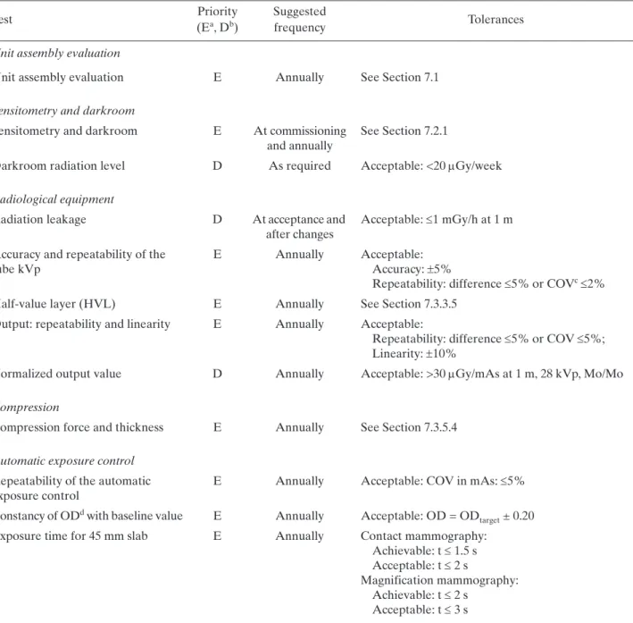
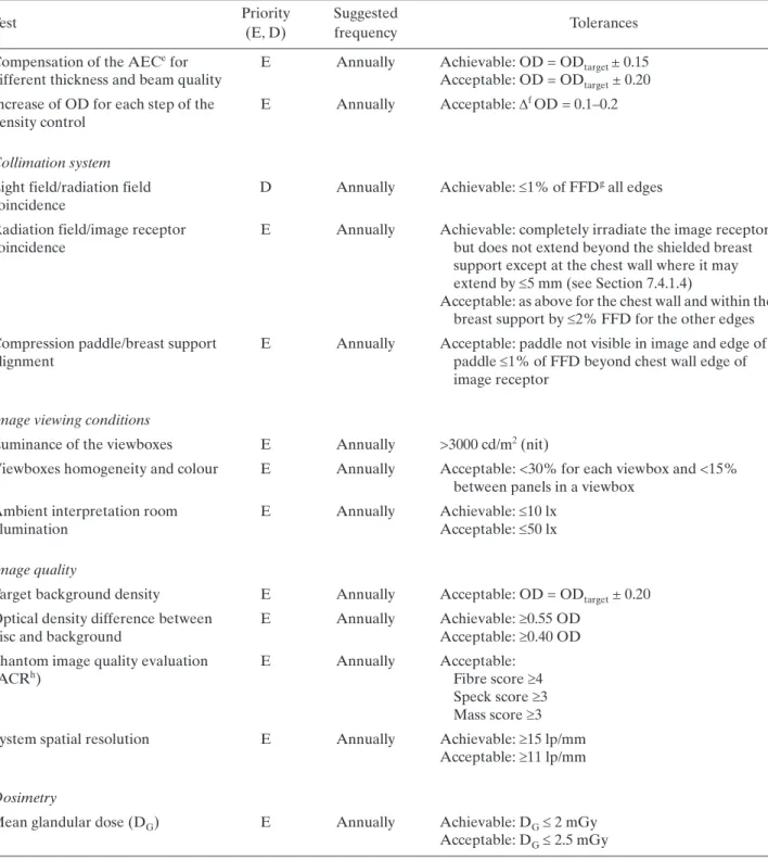
(10) 5.. OUTLINE OF QC TESTS . . . . . . . . . . . . . . . . . . . . . . . . . . . . . . . . . . . . . . . . . . . . . . . . . . . . . . . . . . . . . .. 89. 6.. RADIOGRAPHER’S QUALITY CONTROL TESTS . . . . . . . . . . . . . . . . . . . . . . . . . . . . . . . . . . . . . .. 91. 6.1. Visual inspection . . . . . . . . . . . . . . . . . . . . . . . . . . . . . . . . . . . . . . . . . . . . . . . . . . . . . . . . . . . . . . . . . . 6.1.1. Radiological equipment . . . . . . . . . . . . . . . . . . . . . . . . . . . . . . . . . . . . . . . . . . . . . . . . . . . . . . 6.2. Film storage . . . . . . . . . . . . . . . . . . . . . . . . . . . . . . . . . . . . . . . . . . . . . . . . . . . . . . . . . . . . . . . . . . . . . . 6.2.1. Temperature and humidity . . . . . . . . . . . . . . . . . . . . . . . . . . . . . . . . . . . . . . . . . . . . . . . . . . . . 6.3. Darkroom and film processing . . . . . . . . . . . . . . . . . . . . . . . . . . . . . . . . . . . . . . . . . . . . . . . . . . . . . . . 6.3.1. Darkroom cleanliness . . . . . . . . . . . . . . . . . . . . . . . . . . . . . . . . . . . . . . . . . . . . . . . . . . . . . . . . 6.3.2. Evaluation of temperature, humidity and ventilation conditions . . . . . . . . . . . . . . . . . . . . 6.3.3. White light leakage and safe lights . . . . . . . . . . . . . . . . . . . . . . . . . . . . . . . . . . . . . . . . . . . . . 6.3.4. Automatic processor developer temperature and other parameters . . . . . . . . . . . . . . . . . 6.3.5. Sensitometry . . . . . . . . . . . . . . . . . . . . . . . . . . . . . . . . . . . . . . . . . . . . . . . . . . . . . . . . . . . . . . . 6.3.6. Artefact detection . . . . . . . . . . . . . . . . . . . . . . . . . . . . . . . . . . . . . . . . . . . . . . . . . . . . . . . . . . . 6.3.7. Transition between film emulsion numbers . . . . . . . . . . . . . . . . . . . . . . . . . . . . . . . . . . . . . . 6.4. Imaging system . . . . . . . . . . . . . . . . . . . . . . . . . . . . . . . . . . . . . . . . . . . . . . . . . . . . . . . . . . . . . . . . . . . . 6.4.1. Cleaning of intensifying screens . . . . . . . . . . . . . . . . . . . . . . . . . . . . . . . . . . . . . . . . . . . . . . . 6.4.2. Screen film contact and light tightness of cassettes . . . . . . . . . . . . . . . . . . . . . . . . . . . . . . . 6.4.3. Uniformity of cassette sensitivity, attenuation and artefacts . . . . . . . . . . . . . . . . . . . . . . . . 6.5. Automatic exposure control . . . . . . . . . . . . . . . . . . . . . . . . . . . . . . . . . . . . . . . . . . . . . . . . . . . . . . . . . 6.5.1. Test of system constancy . . . . . . . . . . . . . . . . . . . . . . . . . . . . . . . . . . . . . . . . . . . . . . . . . . . . . . 6.5.2. Test of AEC thickness compensation . . . . . . . . . . . . . . . . . . . . . . . . . . . . . . . . . . . . . . . . . . . 6.6. Image quality . . . . . . . . . . . . . . . . . . . . . . . . . . . . . . . . . . . . . . . . . . . . . . . . . . . . . . . . . . . . . . . . . . . . . 6.6.1. Evaluation of image quality . . . . . . . . . . . . . . . . . . . . . . . . . . . . . . . . . . . . . . . . . . . . . . . . . . . 6.7. Film rejection rate . . . . . . . . . . . . . . . . . . . . . . . . . . . . . . . . . . . . . . . . . . . . . . . . . . . . . . . . . . . . . . . . . 6.7.1. Film rejection rate . . . . . . . . . . . . . . . . . . . . . . . . . . . . . . . . . . . . . . . . . . . . . . . . . . . . . . . . . . .. 93 93 94 94 95 95 96 97 99 100 104 105 106 106 107 109 111 111 114 116 116 118 118. MEDICAL PHYSICIST’S TESTS . . . . . . . . . . . . . . . . . . . . . . . . . . . . . . . . . . . . . . . . . . . . . . . . . . . . . . . .. 119. 7.1. Unit assembly . . . . . . . . . . . . . . . . . . . . . . . . . . . . . . . . . . . . . . . . . . . . . . . . . . . . . . . . . . . . . . . . . . . . . 7.1.1. Unit assembly evaluation . . . . . . . . . . . . . . . . . . . . . . . . . . . . . . . . . . . . . . . . . . . . . . . . . . . . . 7.2. Sensitometry and darkroom . . . . . . . . . . . . . . . . . . . . . . . . . . . . . . . . . . . . . . . . . . . . . . . . . . . . . . . . 7.2.1. Sensitometry and darkroom conditions . . . . . . . . . . . . . . . . . . . . . . . . . . . . . . . . . . . . . . . . . 7.3. Radiological equipment . . . . . . . . . . . . . . . . . . . . . . . . . . . . . . . . . . . . . . . . . . . . . . . . . . . . . . . . . . . . 7.3.1. Radiation leakage . . . . . . . . . . . . . . . . . . . . . . . . . . . . . . . . . . . . . . . . . . . . . . . . . . . . . . . . . . . 7.3.2. Accuracy and repeatability of kVp . . . . . . . . . . . . . . . . . . . . . . . . . . . . . . . . . . . . . . . . . . . . . 7.3.3. Half-value layer (HVL) . . . . . . . . . . . . . . . . . . . . . . . . . . . . . . . . . . . . . . . . . . . . . . . . . . . . . . 7.3.4. Output repeatability and linearity . . . . . . . . . . . . . . . . . . . . . . . . . . . . . . . . . . . . . . . . . . . . . 7.3.5. Compression . . . . . . . . . . . . . . . . . . . . . . . . . . . . . . . . . . . . . . . . . . . . . . . . . . . . . . . . . . . . . . . 7.3.6. Evaluation of the automatic exposure control . . . . . . . . . . . . . . . . . . . . . . . . . . . . . . . . . . . 7.4. Collimation system . . . . . . . . . . . . . . . . . . . . . . . . . . . . . . . . . . . . . . . . . . . . . . . . . . . . . . . . . . . . . . . . 7.4.1. Collimation system . . . . . . . . . . . . . . . . . . . . . . . . . . . . . . . . . . . . . . . . . . . . . . . . . . . . . . . . . . 7.5. Image viewing conditions . . . . . . . . . . . . . . . . . . . . . . . . . . . . . . . . . . . . . . . . . . . . . . . . . . . . . . . . . . . 7.5.1. Luminance and homogeneity of the viewboxes . . . . . . . . . . . . . . . . . . . . . . . . . . . . . . . . . . 7.5.2. Interpretation room ambient illumination . . . . . . . . . . . . . . . . . . . . . . . . . . . . . . . . . . . . . . . 7.6. Image quality . . . . . . . . . . . . . . . . . . . . . . . . . . . . . . . . . . . . . . . . . . . . . . . . . . . . . . . . . . . . . . . . . . . . . 7.6.1. Evaluation of image quality . . . . . . . . . . . . . . . . . . . . . . . . . . . . . . . . . . . . . . . . . . . . . . . . . . . 7.6.2. System spatial resolution . . . . . . . . . . . . . . . . . . . . . . . . . . . . . . . . . . . . . . . . . . . . . . . . . . . . . 7.7. Dosimetry . . . . . . . . . . . . . . . . . . . . . . . . . . . . . . . . . . . . . . . . . . . . . . . . . . . . . . . . . . . . . . . . . . . . . . . . 7.7.1. Incident air kerma at the entrance surface of the phantom . . . . . . . . . . . . . . . . . . . . . . . . . 7.7.2. Determination of the mean glandular dose (DG) . . . . . . . . . . . . . . . . . . . . . . . . . . . . . . . . .. 121 121 122 122 123 123 125 127 129 131 133 136 136 138 138 140 141 141 144 145 145 148. 7..
(11) APPENDIX I:. GUIDELINES FOR THE TRAINING OF A MEDICAL PHYSICIST SPECIALIZING IN MAMMOGRAPHY . . . . . . . . . . . . . . . . . . . . . . . . . . . . . . . . . . . . . APPENDIX II: MAMMOGRAPHY ROOM DESIGN . . . . . . . . . . . . . . . . . . . . . . . . . . . . . . . . . . . . . . . APPENDIX III: DARKROOM DESIGN . . . . . . . . . . . . . . . . . . . . . . . . . . . . . . . . . . . . . . . . . . . . . . . . . . . . APPENDIX IV: TEST EQUIPMENT SPECIFICATIONS . . . . . . . . . . . . . . . . . . . . . . . . . . . . . . . . . . . . . APPENDIX V: AUTOMATIC PROCESSOR DEVELOPER TIME, SPECIFIC GRAVITY, REPLENISHMENT AND pH . . . . . . . . . . . . . . . . . . . . . . . . . . . . . . . . . . . . . . . . . . . . . . . APPENDIX VI: EXAMPLE OF A CALCULATION FOR FILM CROSSOVER PROCEDURE . . . APPENDIX VII: CALCULATION OF AVERAGE FILM GRADIENT . . . . . . . . . . . . . . . . . . . . . . . . . APPENDIX VIII: THE STANDARD BREAST . . . . . . . . . . . . . . . . . . . . . . . . . . . . . . . . . . . . . . . . . . . . . . .. 161 163 164 166. REFERENCES . . . . . . . . . . . . . . . . . . . . . . . . . . . . . . . . . . . . . . . . . . . . . . . . . . . . . . . . . . . . . . . . . . . . . . . . . . . . BIBLIOGRAPHY . . . . . . . . . . . . . . . . . . . . . . . . . . . . . . . . . . . . . . . . . . . . . . . . . . . . . . . . . . . . . . . . . . . . . . . . . .. 167 169. ANNEX I: RADIOGRAPHER’S DATA COLLECTION SHEETS . . . . . . . . . . . . . . . . . . . . . . . . . . . . . . ANNEX II: MEDICAL PHYSICIST’S DATA COLLECTION SHEETS . . . . . . . . . . . . . . . . . . . . . . . . . .. 171 195. GLOSSARY . . . . . . . . . . . . . . . . . . . . . . . . . . . . . . . . . . . . . . . . . . . . . . . . . . . . . . . . . . . . . . . . . . . . . . . . . . . . . . . CONTRIBUTORS TO DRAFTING AND REVIEW . . . . . . . . . . . . . . . . . . . . . . . . . . . . . . . . . . . . . . . . . . .. 217 221. 151 152 155 160.
(12)
(13) 1. INTRODUCTION 1.1. WHY HIGH QUALITY IN MAMMOGRAPHY IS NECESSARY Breast cancer is the most common cancer among women worldwide and is a leading cause of cancer mortality in women. Breast cancer incidence increased 30–40% from the 1970s to the 1990s in most countries, with the most marked increases among women aged 50 years and older, although the incidence for women under 50 years is increasing. Overall, North American and northern European countries have the highest incidence rates of breast cancer; intermediate levels have been reported in western Europe, Oceania, Scandinavia and Israel; the lowest levels are observed in eastern Europe, Central America and South America, and Asia. Breast cancer incidence and mortality rates vary fourfold by geographic location between countries with the highest and lowest rates. Mammography is an X ray examination of the breast. Its principal purpose is to facilitate the detection of breast cancer at a point earlier in its natural history than is possible by clinical examination. It has been demonstrated that routine screening with high quality mammography is effective in reducing mortality from breast cancer in women aged 40–69 years [1, 2]. In countries with such mammography screening programmes, there has been a marked decrease in breast cancer mortality over the past two decades [2]. Mammography is also useful in refining the diagnosis of breast cancer (assessment or workup) after a suspicious area in the breast has been detected and for localizing a lesion for therapy. The radiological signs of breast cancer include mass densities which are typically slightly more attenuating of X rays than the surrounding normal tissue, small microcalcifications, asymmetry between the two breasts and architectural distortion of tissue patterns. In order to detect breast cancer accurately and at the earliest possible stage, the image must have excellent contrast to reveal mass densities and spiculated fibrous structures radiating from them that are characteristic of cancer. In addition, the spatial resolution must be excellent to reveal the calcifications, their number and their shape. The imaging system must have adequate latitude to provide this contrast and resolution over the entire breast effectively. The geometrical characteristics of the X ray unit and the positioning of the breast by the radiographer must be such that as much breast tissue as possible is included in the mammogram. Finally, the noise (signal fluctuation) of the image must be sufficiently low to reveal the subtle structures in a reliable manner and the X ray dose must be as low as reasonably achievable while being compatible with these image quality requirements.. 1.2. PURPOSE It has been well established that to achieve high quality mammography, the following elements are essential: (1) (2) (3) (4) (5). Well trained and experienced personnel (radiologist, radiographer, medical physicist); Modern, well designed equipment; Equipment in good working order; Proper positioning and technical factors for exposure; Appropriate image viewing conditions.. An effective quality assurance (QA) programme is necessary to ensure that all of these elements remain in place over time. The part of this programme that is concerned with the technical aspects is referred to as quality control (QC). This publication is intended to provide a standardized framework for QC for mammography which can be used in Member States. It is intended to provide practical tests to help ensure high quality of screen film mammography. In order to be feasible in areas where resources may be limited, the tests are designed to be carried out with the simplest test equipment possible.. 1.
(14) 1.3. PHILOSOPHY Several well established QC programmes for mammography currently exist in different jurisdictions [3, 4]. These are comprehensive and reflect resources available in those countries. The IAEA recognizes the different resources and needs of Member States and has developed specific programmes for individual areas. An example is a QC programme for mammography developed for the Latin American countries, implemented in the framework of the Regional Cooperative Agreement for the Advancement of Nuclear Science and Technology in Latin America and the Caribbean (known as ARCAL) [5] and associated national protocols [6]. The present report attempts to incorporate the most important components of these programmes in a harmonized manner to be useful to the broad range of Member States. It has been developed with the philosophy that if mammography is to be performed, it must be of high quality in order to allow the earliest detection of cancers. In some areas, both human and technological resources are limited and, therefore, this publication was developed with the concept of practicality in mind. Recent publications indicate that digital mammography can provide equal or superior accuracy to screen film mammography [7]. Digital mammography also has potential for increased efficiency in image archiving and retrieval and the possibility to avoid the costs, complexity and waste disposal problems associated with chemical processing of film. These factors have stimulated interest in the acquisition of digital systems. This presents both opportunities and challenges to those involved in delivering mammography services. Like screen film mammography, it is apparent that the clinical performance of digital mammography depends on the proper design of the equipment and its use in an optimized manner. Therefore, one of the important challenges is to have in place in a timely fashion an appropriate framework of QA for digital mammography systems. The present publication addresses only QA issues relevant to screen film mammography. It is intended that an additional publication will address the specific issues associated with the use of digital mammography.. 2.
(15) 2. ELEMENTS OF HIGH QUALITY MAMMOGRAPHY 2.1. PERSONNEL There are many elements that contribute to the mammography process. The experience of personnel directly and indirectly involved in the mammographic task is crucial to the final outcome. In that respect, it is essential that: — The mammography images be acquired by experienced radiographers trained specifically in mammography (see Section 4.1, for example, on the importance of correct positioning and the use of compression); — The images be interpreted by an appropriately trained and experienced radiologist; — A medical physicist be available as a consultant to the facility. This may be either on a full time or part time basis, according to the needs of the facility in QA and radiation protection. (See Section 3.2.4 and Appendix I for the specific requirements that a medical physicist should meet.) The availability and qualifications of the medical physicist must be in compliance with local regulations.. 2.2. EQUIPMENT 2.2.1.. Mammography unit The X ray unit must be specifically designed for mammography and include the following key features:. — X ray tube with a nominal focal spot of 0.3 mm [8]; — If magnification mammography is performed (this capability should be present on systems that are used for diagnostic mammography and not exclusively for screening), a magnification stand and a second, smaller focal spot of nominal size 0.15 mm; — Molybdenum target. Supplementary targets composed of materials such as tungsten or rhodium may also be available; — Tube current 80 mA for a Mo target for contact mammography and 20 mA for magnification mammography; — Beryllium exit window; — Beam filter of molybdenum. An additional filter composed of rhodium is highly desirable; — Motorized compression device; — Readout of compression thickness and force is highly desirable; — Automatic exposure control (AEC) with a sensor whose position is adjustable; — Fine control of optical density on AEC; — Moving grid designed for mammography; — Focus–film distance 60 cm; — Buckys that can accommodate film of sizes 18 cm × 24 cm and 24 cm × 30 cm are desirable. The room in which the mammography unit is sited should have a stable temperature and humidity for satisfactory operation. This may require appropriate air conditioning. More complete details for siting a mammography unit are provided in Appendix II. 2.2.2.. Image receptor system An acceptable image receptor system is characterized by having:. — Cassettes designed for mammography; — A high resolution single mammography screen in cassette; — Appropriate mammography film matched to be used with the selected screen.. 3.
(16) 2.2.3.. Processing Acceptable film processing requires:. — Automatic processor with digital readout of developer temperature. — Appropriate replenishment system for mammography, matched to the film volume processed at the facility. — Use of processing chemicals matched to the film that is used. — Correct processing time, temperature and replenishment setting. — Proper water quality and temperature control. — If a darkroom is used, it must be free of light leaks and internal light sources that could fog the film. The level of ionizing radiation in the darkroom must also be within acceptable tolerances. — Darkroom, cassettes and screens must be free from dust that could cause artefacts in the mammograms. — Proper ventilation of processing area. — Appropriate storage of films and chemicals. — Management of film and chemical inventory to ensure that fresh materials are used for imaging. See Appendix III for more details on some of the requirements mentioned. 2.2.4.. Viewing conditions Successful viewing conditions require:. — A viewbox designed for mammography with luminance 3000 cd/m2; — Lamps in the viewbox matched for brightness and colour; — The ability to mask edges of mammograms; — Low ambient light in the room. 2.2.5.. Quality assurance. To ensure high quality, all of the above factors are necessary; however, in addition, it is essential that a comprehensive QA programme be in place. It is also imperative that time be allocated to allow the necessary QC tests to be performed regularly, that results be carefully recorded and that corrective action be taken promptly when indicated. The basic elements of a QA programme in mammography are outlined in Section 3. 2.2.6.. Regular maintenance. In addition to regular quality assurance, it is also essential that all mammographic units and associated film processors undergo regular maintenance consistent with best practice or recommendations from the manufacturers.. 4.
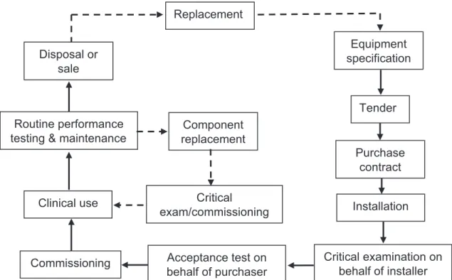
(17) 3. BASIC PRINCIPLES OF QUALITY ASSURANCE IN MAMMOGRAPHY 3.1. QUALITY ASSURANCE ACTIVITIES A QA programme in diagnostic radiology, as defined by WHO [9], is an organized effort by the staff operating a facility to ensure that the diagnostic images produced are of sufficiently high quality so that they consistently provide adequate diagnostic information at the lowest possible cost and with the least possible exposure of the patient to radiation. Registrants and licensees shall establish a comprehensive QA programme for medical diagnosis with the participation of appropriate medical physicists, taking into account the principles established by WHO [9]. QA programmes for medical exposures shall include: (1) (2) (3). (4) (5) (6). Measurements of the physical parameters of the radiation generators and imaging devices at the time of commissioning and periodically thereafter. Verification of the appropriate physical and clinical factors used in patient diagnosis (or treatment). Written records of relevant procedures and results. This includes a manual that defines clear lines of responsibility, outlines the individual QC tests performed, gives the test frequencies, is useful for staff training, facilitates audit of a service and helps to keep information within the service. Verification of the appropriate calibration and conditions of operation of the dosimetry and monitoring equipment. Optimization of clinical protocols and equipment operation to achieve the aims of QA as stated previously. Regular and independent quality audit reviews of the QA programme.. QA programmes are designed to ensure that the radiology equipment and staff procedures yield the desired information. They include: (1). (2). Administrative procedures or management actions designed to verify that: — QC tests are performed properly and according to a planned timetable; — Results of these tests are evaluated promptly and accurately; — The necessary corrective measures are taken in response to these results; — There is an appropriate assignment of responsibility for QA actions; — Standards of quality are established for equipment in the facility; — Adequate training is provided; — Appropriate equipment for each examination is selected, including the writing of adequate equipment specifications. Acceptance testing and commissioning (see Fig. 1): — Acceptance tests are those performed to verify that the purchase specifications have been met by the vendor. These tests are often performed by the company installing the equipment, under the supervision of the medical physicist [10] or, preferably, independently by the medical physicist. — Commissioning tests are those undertaken at the time the equipment is put into service; they are used to establish baseline levels of performance and are performed by the medical physicist. — To a large extent, these tests overlap. This publication primarily describes tests that form a comprehensive, ongoing QC programme for mammography, but it is recognized that it is necessary to ensure that the equipment as delivered conforms to specified standards and that appropriate initial baseline values are established and used to ensure the maintenance for the quality of the equipment throughout its service life. These acceptance and commissioning tests are included in this publication and are indicated as such. During acceptance testing, a qualified person should check the electrical and mechanical safety of any new installation.. 5.
(18) Replacement Equipment specification. Disposal or sale. Tender Routine performance testing & maintenance. Component replacement Purchase contract. Clinical use. Critical exam/commissioning. Installation. Commissioning. Acceptance test on behalf of purchaser. Critical examination on behalf of installer. FIG. 1. Life cycle of a piece of equipment.. (3) (4) (5). (6) (7). (8). 6. QC tests (also classified as either constancy or status tests by the IEC) are used to test the components of the radiological system and verify that the equipment is operating satisfactorily. Verification of QC equipment and material. Follow-up of any corrective actions proposed: — It is important that routine QC testing be properly performed in the mammography facility and that results be documented thoroughly and carefully. It is equally important that problems and potential problems be clearly documented and communicated to the facility in a timely manner and that the medical physicist be assured that the receiving party has received and understood the supplied information. This is especially the case when safety concerns are raised. — The reporting structure in the facility should be understood by the medical physicist, who should ideally report problems to an individual who is empowered to call in service personnel and, if necessary, who can ensure that the equipment is not used until the problems are corrected. The medical physicist may be asked to explain the problems to service personnel and share test results with them. The medical physicist and the representative from the facility should work together to ensure that the problems have been appropriately corrected. Education and training of staff, including the radiologist, radiographer and medical physicist: each must meet a minimum level of qualification. Continuing education: Each team member must undertake sufficient continuing education to ensure that they are up to date on new techniques and that they are refreshed relative to their basic knowledge, for example, of radiation safety. Experience: To ensure proficiency on an annual basis, the radiologist must read a sufficient number of cases; the radiographer must do a minimum number of cases; and the medical physicist must perform a sufficient number of acceptance tests and carry out routine QC testing on a sufficient number of mammography units..
(19) 3.2. ROLES AND RESPONSIBILITIES 3.2.1.. The owner. The owner has specific responsibilities to ensure that all regulatory and/or licensing requirements are met. Further, the owner must ensure that all radiologists, radiographers, medical physicists and other personnel who work at the facility are appropriately qualified and trained, and meet all continuing education and experience requirements. It is the responsibility of the owner to ensure that a QA programme is in place encompassing all aspects of the mammography imaging process. The specific tasks within that programme may be delegated to appropriate staff who may have more expertise to carry out those tasks. Notwithstanding the above delegation, it remains the ultimate responsibility of the owner that the elements of the QA programme are fulfilled. A lead interpreting physician (LIP), usually a mammography radiologist, should be identified by the mammography facility to have the specific responsibility of ensuring that all required QA activities are performed. 3.2.2.. Lead interpreting physician (radiologist). Although it is recognized that the LIP will delegate many of the following tasks, the LIP still has the responsibilities for: (1). Ensuring that the technical personnel and/or radiographers have adequate training and continuous education courses in mammography. (2) Motivating, supervising and managing all the aspects related to the QC programme in the area of mammography. (3) Providing an orientation programme for radiographers based on a carefully established procedures manual. (4) Selecting a single radiographer to be the primary QC radiographer to perform the prescribed QC tests and oversee those that have been delegated to other individuals. (5) Ensuring the availability of the equipment and necessary materials for implementation of the QC tests. (6) Arranging staffing and scheduling so that adequate time is available to carry out the QC tests and to record and interpret the results. (7) Ensuring that a medical physicist is available to oversee the equipment related QC programme and to perform the medical physicist’s tests. (8) Reviewing the radiographer’s test results at least every three months, or more frequently if consistency has not yet been achieved; and reviewing the medical physicist’s test results annually, or more frequently when needed. (9) Overseeing, or designating an individual to oversee, the radiation protection programme for employees, patients and other individuals in the surrounding area. (10) Ensuring that records concerning employee qualifications, mammography technique and procedures, infection control procedures, QC, safety and protection are properly maintained and updated. (11) Providing feedback continually, both positive and negative, to the technical personnel and/or radiographers, on the image quality and the QC procedures. (12) Verifying the percentage of rejected films performed by the radiographers and ensuring that if it exceeds the specified limit, appropriate corrective action is implemented. 3.2.3.. Radiographer (technologist) The responsibilities of the radiographer include:. (1). Ensuring that the QC tests are performed, interpreted and recorded appropriately. This is best achieved when one radiographer assumes overall responsibility for QC matters and is able to train others to assist in QC activities.. 7.
(20) (2) (3) 3.2.4.. Recording imaging problems. Undertaking additional continuous education courses in mammography. Medical physicist. The medical physicist is a person trained in medical physics and certified as a medical physicist according to the applicable programme in the Member State, if such a programme exists. Guidelines for the training of a medical physicist are given in Appendix I. If it is not possible to have a medical physicist carry out the specified medical physicist’s tests in this document, then such tests may be delegated to a trained radiographer or to a service person employed by the vendor of the mammography equipment. The minimum requirements for an individual who is delegated to carry out the annual medical physicist’s QC tests described in this publication are: (1) (2) (3). Training in radiation safety; Training in the physics of mammography; Practical training in the testing of mammography equipment. The responsibilities of the medical physicist include:. (1) (2) (3) (4). 8. Advising the facility on the safe and effective use of X rays for mammography. This includes image quality and radiation protection of the patient and personnel. Advising the facility on equipment for mammography. Conducting tests to ensure the safety and proper performance of equipment used in mammography. These tests include acceptance, commissioning and routine QC tests. Providing oversight and advice to the radiographer who carries out the radiographer’s component of the QC programme..
(21) 4. CLINICAL IMAGE QUALITY 1 For copyright reasons, the AND material in Chapter 4 is available in the hard copy version only of this 4.1. PATIENT POSITIONING COMPRESSION publication.. 4.1.1.. Introduction. Breast positioning is an art that has undergone significant changes recently. Incorrect positioning is the most common problem encountered when evaluating clinical images. When mammography and xeromammography were performed with conventional X ray equipment, positioning was limited to manoeuvres in which the patient was turned while lying on her side or seated directly under the overhead tube. With the evolution of dedicated equipment that allows rotation of the X ray tube, the possibilities for breast positioning became greater. Rather than relying on methods that were based on traditional radiographic projections (lateral and craniocaudal), the art of positioning has been refined by combining a better understanding of the breast’s anatomy and mobility with the greater versatility of modern dedicated equipment. In addition, it is now understood that breast positioning should be tailored to the patient’s specific habitus and breast problem. Today, the resourceful radiologist and radiographer can rely on a great variety of positioning techniques to improve breast cancer detection and facilitate the evaluation of breast abnormalities. This section provides a guide to performing: (1) (2) (3). Standard views for screening; Views used to localize the exact position of an abnormality in the breast; Views used to better define the nature of an abnormality.. Methods for performing mammograms under special circumstances, with challenging patients, for example, are also included. The views are named in accordance with new ACR recommendations for standardized mammographic terminology. Table 1 presents each of the views discussed in this section, along with its new recommended labelling code and its purpose.. 1. The material in this chapter is drawn from the Mammography Quality Control Manual of the American College of Radiology (ACR), and is reprinted with permission of the ACR. No other representation of this material is authorized without expressed, written permission from the ACR. Some of the textual references, for example, are to the Mammography Quality Standards Act (MQSA) requirements in the USA, and do not have mandatory application to Member States. They are included as part of the agreement with the ACR to reproduce their text in full in this technical report.. 9.
(22) 5. OUTLINE OF QC TESTS QC tests are intended to verify the stability in the operation of the equipment or elements used to acquire the mammogram. The tests have been classified into two types: essential and desirable, with respect to their importance in influencing image quality and dose. The performance of the first category of tests is considered indispensable; however, it is recommended that the tests in the second category be carried out if adequate human resources and equipment can be made available. Test Priority Essential refers to tests that must be done in a facility. Desirable describes the test procedures that should be performed if feasible.. Many of the tests need to be performed very frequently (weekly and daily). Therefore, it is recommended that these tests be performed by local personnel who are present daily in the installation (technical personnel, normally radiographers). The lower frequency tests have been assigned in the majority of the cases to medical physicists and radiologists. Tolerance values for the tests are indicated. Again, these are classified into two categories: acceptable and achievable. In some cases, only the acceptable level has been defined.. Performance Standards Acceptable indicates that performance must be within these tolerances and if it is not, the equipment should not be used. Achievable indicates the level of performance that should be attained under favourable circumstances; this is the level at which a facility should work if it is feasible.. A facility should strive to ensure that equipment operates at the achievable level of performance, as this will produce the highest image quality and the most appropriate dose performance. It is recognized, however, that limited resources and other factors may occasionally prevent the achievable levels from being obtained. In no case should the facility continue to perform mammography if the equipment does not meet the acceptable standard of operation, because below this level the value of the procedure and/or its safety is considered unacceptable. Each test in the QC programme has a specified tolerance level for achievable and acceptable results as applicable. Should the results of a test fall outside the specified tolerance, the test should usually be repeated to confirm the result before action is taken. Suitable minimum specifications for test equipment are provided in Appendix IV. Table 2 in Chapter 6 and Table 4 in Chapter 7 list all the tests to be carried out by the radiographer and the medical physicist, respectively. In some cases, either could perform a particular test, so the tests are listed in both tables. In such cases, a decision must be made as to who will actually do the test and that person should consistently do the test thereafter.. 89.
(23) ..
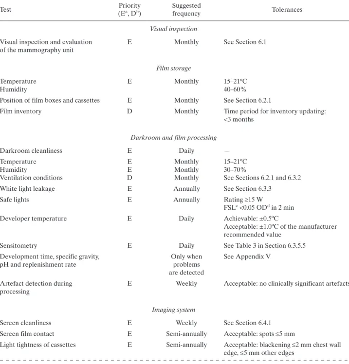
(24) 6. RADIOGRAPHER’S QUALITY CONTROL TESTS A brief description of the methodology to be undertaken when performing the radiographer’s QC tests is provided in this section (Table 2). The order in which tests appear in this publication does not necessarily indicate that in which they should be performed. The preferred order will depend on various factors relating to the mammography facility as well as the evaluator’s preferences, always having in mind that tests exist whose results affect the execution of others. Data collection sheets are found in Annex I and are available in electronic format.. TABLE 2. LIST OF RADIOGRAPHER’S QUALITY CONTROL TESTS Test. Priority (Ea, Db). Suggested frequency. Tolerances. Visual inspection Visual inspection and evaluation of the mammography unit. E. Monthly. See Section 6.1. Film storage Temperature Humidity. E. Monthly. 15–21ºC 40–60%. Position of film boxes and cassettes. E. Monthly. See Section 6.2.1. Film inventory. D. Monthly. Time period for inventory updating: <3 months. Darkroom and film processing Darkroom cleanliness. E. Daily. Temperature Humidity Ventilation conditions. E E D. Monthly Monthly Monthly. — 15–21ºC 30–70% See Sections 6.2.1 and 6.3.2. White light leakage. E. Annually. See Section 6.3.3. Safe lights. E. Annually. Rating 15 W FSLc <0.05 ODd in 2 min. Developer temperature. E. Daily. Achievable: ±0.5ºC Acceptable: ±1.0ºC of the manufacturer recommended value. Sensitometry. E. Daily. See Table 3 in Section 6.3.5.5. Development time, specific gravity, pH and replenishment rate Artefact detection during processing. Only when problems are detected E. Weekly. See Appendix V. Acceptable: no clinically significant artefacts. Imaging system Screen cleanliness. E. Weekly. See Section 6.4.1. Screen film contact. E. Semi-annually. Acceptable: spots 5 mm. Light tightness of cassettes. E. Semi-annually. Acceptable: blackening 2 mm chest wall edge, 5 mm other edges. 91.
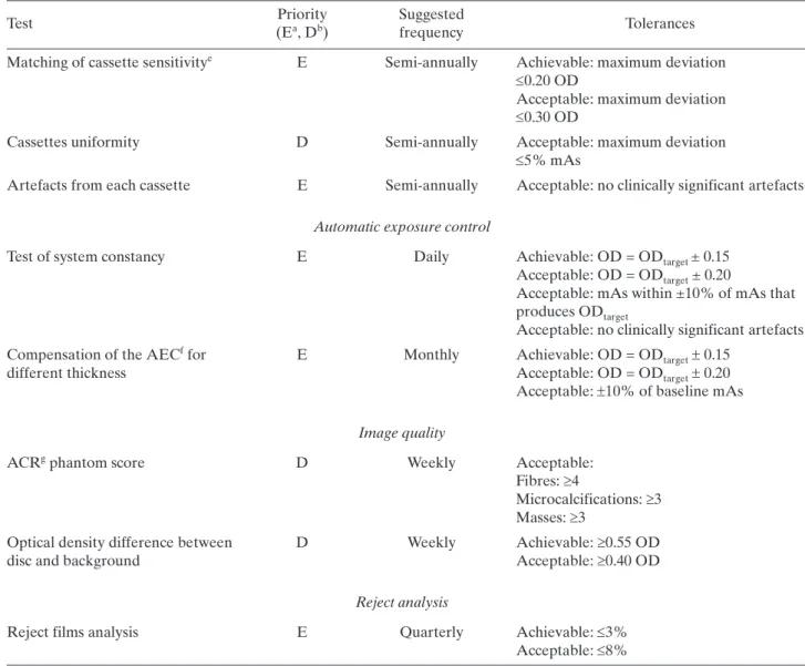
(25) TABLE 2. LIST OF RADIOGRAPHER’S QUALITY CONTROL TESTS (cont.) Priority (Ea, Db). Suggested frequency. Matching of cassette sensitivitye. E. Semi-annually. Achievable: maximum deviation 0.20 OD Acceptable: maximum deviation 0.30 OD. Cassettes uniformity. D. Semi-annually. Acceptable: maximum deviation 5% mAs. Artefacts from each cassette. E. Semi-annually. Acceptable: no clinically significant artefacts. Test. Tolerances. Automatic exposure control Test of system constancy. E. Daily. Compensation of the AECf for different thickness. E. Monthly. Achievable: OD = ODtarget ± 0.15 Acceptable: OD = ODtarget ± 0.20 Acceptable: mAs within ±10% of mAs that produces ODtarget Acceptable: no clinically significant artefacts Achievable: OD = ODtarget 0.15 Acceptable: OD = ODtarget 0.20 Acceptable: 10% of baseline mAs. Image quality ACRg phantom score. D. Weekly. Acceptable: Fibres: 4 Microcalcifications: 3 Masses: 3. Optical density difference between disc and background. D. Weekly. Achievable: 0.55 OD Acceptable: 0.40 OD. Reject analysis Reject films analysis a b c d e f g. E. E: Essential, basic requirement. D: Desirable, recommended. FSL: Fog due to the safety light. OD: Optical density. This includes speed of screens and cassette attenuation. AEC: Automatic exposure control. ACR: American College of Radiology.. 92. Quarterly. Achievable: 3% Acceptable: 8%.
(26) 6.1. VISUAL INSPECTION 6.1.1.. Radiological equipment. 6.1.1.1. Scope — Objective: To verify the mechanical and electrical operation of the mammography unit; — References [3, 11]; — Frequency: Monthly. 6.1.1.2. Instrumentation (1) (2). Spirit level. Tape measure.. 6.1.1.3. Methodology Execute the visual verification of the operation of the X ray machine following the checklist shown on the data collection sheet. 6.1.1.4. Recommendations and corrective actions (1) (2) (3). If some of the movements or control scales are not functioning correctly, the technical service should be called for immediate repair. If the generator or the compression is not functioning, mammography should not be performed until the problem has been corrected and proper performance of the system has been verified. If some of the components related to unit electrical safety show problems of electric discharges or the high voltage electrical wiring is damaged, the technical service should be called for immediate repair.. 93.
(27) 6.2. FILM STORAGE 6.2.1.. Temperature and humidity. 6.2.1.1. Scope — Objectives: To verify temperature and humidity of the storage place for films and chemicals; to check the positioning and organization of film boxes, cassettes and chemicals; to verify proper storage and utilization order of the film and chemicals; — References [3, 5, 11, 12]; — Minimum frequency: Monthly and after changes such as renovation and relocation. 6.2.1.2. Instrumentation (1) (2). Thermometer. Hygrometer.. 6.2.1.3. Methodology (1) (2) (3). Measure the temperature and humidity level at the storage place. Observe the positioning and organization of film boxes. Review the film inventory.. 6.2.1.4. Interpretation of results and conclusions Tolerances:2 (1) (2) (3) (4). (5). Temperature: Manufacturers’ recommendations (15–21ºC). Humidity: 30–70%. Cassettes should be stored vertically. Film boxes should be located in a vertical position (never horizontally in order to avoid films being damaged or suffering artefacts due to the weight of film boxes placed one on top of another) and organized in chronological order in accordance with their expiration date. This placement system facilitates control of the inventory and ensures that the oldest boxes are used first. Time period for inventory updating: <3 months.. 6.2.1.5. Recommendations and corrective actions (1) (2). If positioning and organization of film boxes, cassettes and chemicals is not appropriate, communicate this to the responsible person for the service. If the environmental conditions do not fulfil the specifications of the film and chemical manufacturers, investigate the causes and inform the person responsible for undertaking corrective measures.. 2. 94. For films and chemicals, the storage temperatures should be those recommended by the manufacturers..
(28) 6.3. DARKROOM AND FILM PROCESSING 6.3.1.. Darkroom cleanliness. 6.3.1.1. Scope — Objective: To maintain cleanliness in the darkroom in order to minimize possible artefacts on the X ray films; — References [3, 5, 12]; — Minimum frequency: Every day before beginning the working day. 6.3.1.2. Instrumentation (1) (2). Bucket. Lint-free cloths.. 6.3.1.3. Methodology (1) (2) (3). Once a week, clean or vacuum the grills of the air ventilation channels, safety lights and walls. Clean all the work surfaces with a wet cloth. Clean the tray that receives the film in the processor. Ensure that the darkroom floor is clean.. 6.3.1.4. Interpretation of results and conclusions The dirt present in the darkroom affects the quality of the mammographic images, as it is introduced into the cassettes when they are handled. Such dirt becomes affixed in the form of powder specks on the intensifying screens, producing artefacts (spots of variable size) which can be observed after developing the films. Such spots can interfere with the detail of the mammographic image of diagnostic interest. Accordingly, part of the evaluation of darkroom cleanliness is to observe whether these artefacts exist in the developed films. 6.3.1.5. Recommendations and corrective actions (1) (2) (3) (4) (5) (6) (7). It is advisable for darkroom walls to be covered with a paint that does not produce reflections, preferably a dull oil paint. The ingestion of food and beverages, and smoking must not be allowed in the darkroom. It is necessary to ensure that hands are clean and dry at all times. It is advisable to eliminate any object that contributes to dust accumulations. False ceilings (e.g. suspended soft tiles) should be avoided, as they allow the buildup of dust and dirt which can easily be dislodged and fall into the processor, into open cassettes or onto films. It is recommended that the air supplied to the darkroom be filtered. Any of these actions should be documented in the comments section on the data collection sheet.. 95.
(29) 6.3.2.. Evaluation of temperature, humidity and ventilation conditions. 6.3.2.1. Scope — Objective: To verify temperature, humidity and ventilation conditions in the darkroom; — References [3, 5, 6, 11, 12]; — Minimal frequency: Monthly and after changes. 6.3.2.2. Instrumentation (1) (2). Thermometer. Hygrometer (if available).. 6.3.2.3. Methodology (1) (2) (3). Measure the temperature and the humidity level of the darkroom. Note the values on the data collection sheet. Check whether a strong odour of processing chemicals is present. Confirm the existence and operation of the air circulation system (pay special attention to the air extractor if there is one). Evaluate the exhaust fan operation. ‘Flutter test’ (see also Appendix III.7, item (8) in the list of darkroom ventilation conditions: “…with the processor turned off, a piece of tissue is to be held near the gap in the exhaust duct. The tissue should be seen to be drawn towards the gap. If there is not noticeable movement in the tissue, the flexible duct is to be removed and the negative pressure measured 25 cm into the opening of the duct, using a manometer.”).. 6.3.2.4. Interpretation of results and conclusions Tolerances: (1) (2) (3) (4). Temperature: 15–21ºC. Humidity: 30–70%. There should be no perceived odour of developing chemicals in the darkroom (this is a sign of deficient air circulation). The ‘flutter test’ fails if there is inadequate suction, or if the tissue blows away from the gap.. 6.3.2.5. Recommendations and corrective actions If the environmental and ventilation conditions are outside of the tolerable range, as seen from the ‘flutter test’, the causes should be investigated and the service responsible informed about the actions that should be carried out.. 96.
(30) 6.3.3.. White light leakage and safe lights. 6.3.3.1. Scope — Objective: To confirm that safe lights and possible leakage of white light in the darkroom do not produce fog on the mammographic films; — References [3, 11–13]; — Minimum frequency: Annually unless problems are found. The test should be repeated when the safe light bulbs or filters are changed. 6.3.3.2. Instrumentation (1) (2) (3) (4) (5) (6) (7). Mammographic unit. Phantom (45 mm of PMMA or ACR phantom). Densitometer. Mammographic film. Opaque paper. Cassettes. Stopwatch.. 6.3.3.3. Methodology (1) Ensure that filters, safe light bulb power, and the distance between filter and work surfaces are the recommended ones, and that the lamp is directed to the ceiling. (2) Turn off all the lights in the darkroom and wait for 5 min in order to adapt to the darkness. (3) Observe if there is any white light leaking around the doors, the processor, film exchange boxes, extractors or the ceiling. If there is any white light leakage, correct it before continuing. (4) In complete darkness, load a cassette with a film.3 (5) Place the cassette in the cassette holder of the mammography unit. (6) Place the phantom on the image receptor, aligned with the chest wall side and centred between the two lateral sides. (7) Lower the compression paddle until it is in contact with the phantom. (8) Confirm the position of the automatic exposure control device: it should be placed in the centre of the phantom. (9) Make an exposure with the automatic exposure control or select those factors used to obtain the image of an average breast (of 45 mm of thickness). If a phantom is not available, expose the film in order to obtain an optical density in the range of the target optical density 1.5–1.9 optical density (OD). (10) With the darkroom in complete darkness, take out the film from the cassette and place it on the work surface with the emulsion side upwards. Cover half of the film with the opaque paper, placing it perpendicularly to the corresponding side to the chest wall edge of the film. (11) Turn on the safety lights and wait 2 min. (12) Process the film. (13) Measure the optical density of the image in the side that has been covered with the opaque paper (if using the ACR phantom, avoid measuring the density in the location of the phantom details, such as specks, masses and fibres). (14) Measure the optical density at a point adjacent to the previous one, but in an area that is in the part directly exposed to the safety lights. (15) Take note of both optical densities. This difference is used to evaluate the fog produced by the safe lights (FSL). (16) Record the FSL value on the data collection sheet.. 3. If more than one type of film is used, this test should be repeated for each type of film.. 97.
(31) (17) Document the execution of this test on the data collection sheet. (18) If not previously done, use a permanent marker to write the installation date on the safe light filters. 6.3.3.4. Interpretation of the results and conclusions Tolerances: (1) (2) (3). Bulb power: 15 W; FSL: 0.05 in 2 min at work surface (i.e. where the cassettes are handled); White light leakage should not be observed.. 6.3.3.5. Recommendations and corrective actions If FSL exceeds the tolerance, corrective measures should be implemented immediately. If the problem is not solved, the cassettes should be loaded only in complete darkness. The leading causes of fog are: — Incorrect or expired filters; — Cracks in the filters or in the lamp housings; — Safe lights too near to the work surfaces; — Incorrect bulb power (higher than 15 W); — Indicator lights in the processor, clocks, etc.; — Entry of light around the doors, processor or film exchange boxes; — Light leakage in the ceiling (especially tile ceilings) or through ventilation ducts. See also Appendix III for more complete advice about darkroom design.. 98.
(32) 6.3.4.. Automatic processor developer temperature and other parameters. 6.3.4.1. Scope — Objective: To verify the developer temperature;4 — References [3, 4, 12, 14]; — Minimal frequency: Daily. 6.3.4.2. Instrumentation Digital thermometer: ±0.1ºC (never use mercury). If the processor is equipped with built-in digital temperature readout, this can be used provided that its accuracy has been confirmed in the past year. 6.3.4.3. Methodology (1) (2). After the processor is turned on, wait enough time for the developer temperature to become stabilized. If an external thermometer is used for this test, introduce the thermometer into the developer tank. Record the reading and the time on the data collection sheet.. 6.3.4.4. Interpretation of results and conclusions Tolerances: Achievable: ±0.5ºC; Acceptable: ±1.0ºC or the value indicated by the film manufacturer. Check that the temperature indicator is working appropriately. 6.3.4.5. Recommendations and corrective actions If the temperature is found to be outside of tolerances, contact the service representative.. 4. Note: For other processor related measurement tests, such as development time, specific gravity, replenishment rate and pH, the services of a specialized technician are recommended. If this is not possible, some test procedures are suggested in Appendix III.. 99.
(33) 6.3.5.. Sensitometry. 6.3.5.1. Scope — Objective: To verify that the processor is working in a stable manner; — References [3–5, 11–17]; — Minimal frequency: Daily and after changes. 6.3.5.2. Instrumentation (1) (2) (3). (4) (5). Sensitometer. Mammography film. Densitometer. If a densitometer/computer system capable of automatically determining sensitometry information is available, such as film gradient and speed (S) at a set density, this is highly desirable and should be used. However, the main procedures described here assume that this is not available and use speed and contrast indices to establish processor performance. Viewbox. Thermometer.. 6.3.5.3. Methodology Establishing the initial operating levels It may be useful for the medical physicist to work with the radiographer in establishing initial operating levels at the time the processor is installed. These levels may have to be revised when changes are introduced in: — Film type (see Section 6.3.7); — Chemical products brand; — Developer and fixer temperatures; — Replenishing rate of the developer and fixer; — Development time; — Sensitometer and densitometer; — Significant processor components; — Film box (see Section 6.3.7). Steps: (1) (2). (3) (4). 100. Confirm that the darkroom meets the adequate conditions in accordance with the tolerances defined in Section 6.3.1. Clean as required the processor, mixing and or replenishment tanks and chemistry feed lines. (Be careful not to use cleaning agents that will leave chemical residues which will change the required pH levels.) Mix developer and fixer solutions for the replenishment tanks, ensuring that the specific gravity and pH are as specified by the manufacturer. Chemistry should be added to the processor. Note that starter solution may be required to be added to the replenisher developer to ‘restrain’ the developer. Confirm that the displayed developer temperature is consistent with that recommended by the manufacturer for the films in use. Confirm that the replenishment rate for the chemicals is as specified by the manufacturer..
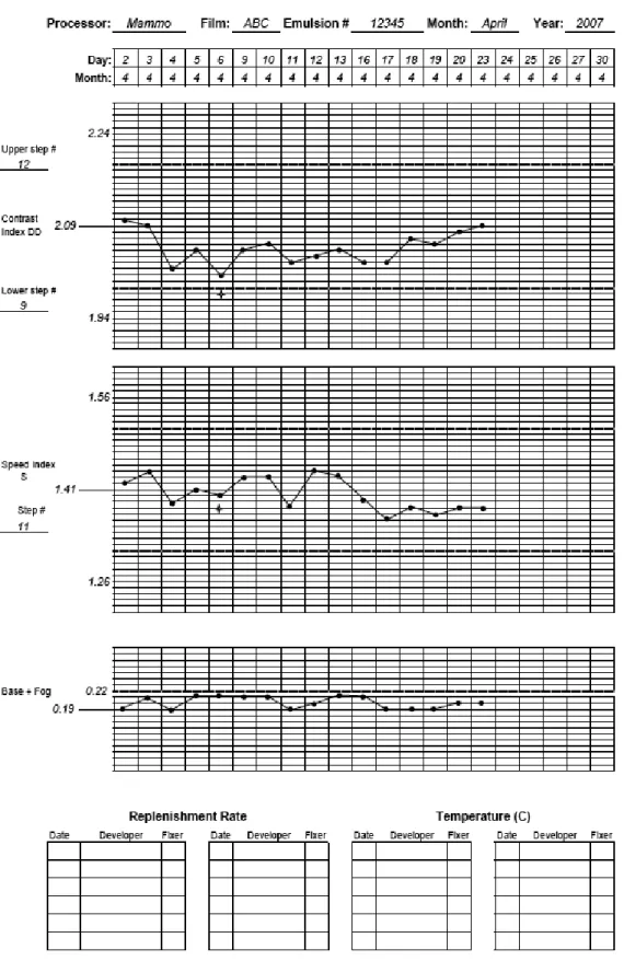
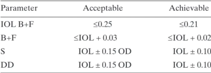
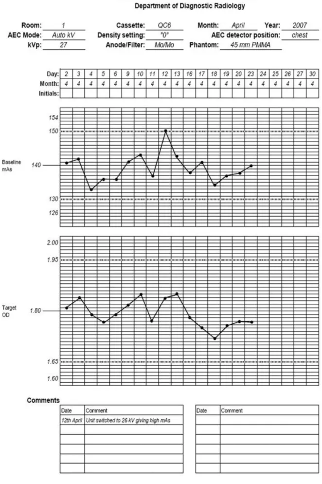
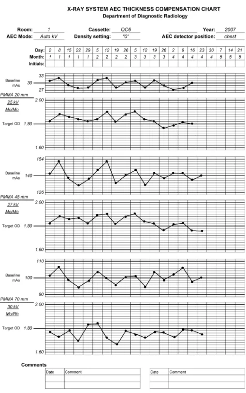
(34) (5) (6) (7). (8) (9) (10). (11). (12). (13) (14) (15). Expose the film on the emulsion side using the sensitometer5 with the control set to green light (for orthochromatic films). Use the densitometer to measure the optical densities of each step on the test film. Make the measurements in the centre of each step. Repeat the previous action for five consecutive days. The sensitometry should be carried out at the same hour of the day and the film should be placed on the input tray of the processor in the same orientation (i.e. short axis of the film parallel to the feed direction and emulsion side uppermost). Measure with the densitometer the densities of each step of the five test films obtained. Carry out the measurement in the centre of each step. Obtain the average values for each step using the reading of the five initial patterns. Determine the step number with average density closest to (but not lower than) 1.20 OD. Identify this step as the speed index step. Note the number of the step and the value of its average density on the data collection sheet. This OD is the initial operating level (IOL) for S. (In daily control tests, this step number will be used to measure the value of S.6) Determine the step number with average density above 2.20 OD but closest to 2.20 OD. Identify it as the step of high density (HD) and note the step number and OD on the data collection sheet. The difference between the average densities of HD and S is called density difference (DD). Record DD on the data collection sheet. This difference is the IOL for DD. (In daily QC tests, these steps and their difference will be used to obtain the value of DD.) If an automatic densitometer is used, it will also provide a graph of the gradient versus OD, step number or log exposure level. Identify as density of base plus fog (B+F) the average density value of the first step of the pattern of densities (or of any unexposed area). Note the value on the data collection sheet. This is the IOL for B+F. (In daily QC tests, this step will be used to obtain the value of B+F.) Write the IOL values obtained in steps (10)–(12) near the central lines of the three corresponding graphs and on the data collection sheet (see example in Fig. 42). Establish in each part of the processor control sheet, the higher and lower tolerances for S, DD and B+F (see section on results interpretation and conclusions). Note that the IOL should not be revised on a daily basis but should be revised only when new conditions in the processor or film emulsion cause the daily DD values to consistently move away from the IOL and approach the control limit (IOL ± 0.15).. 6.3.5.4. Quality control daily tests Sensitometry should be carried out every day at the beginning of the workday, after the processor has reached its proper operating temperature and before processing the first film: (1) (2) (3) (4) (5). Expose the film using the sensitometer and process it7 before processing any daily mammography. Measure the densities in the steps obtained upon establishing the IOLs. Note the values of S, B+F, and DD on the data collection sheet. Plot the values of S, DD and B+F on the processor QC sheet. Determine if any point is outside the tolerance values. If none is, proceed to point (7). If there are points outside the tolerances, repeat the test. If after that they are still outside the tolerances, investigate the possible causes and correct the problem. Repeat the test again in order to verify that the. 5. Verify that the sensitometer emits light from a single side, since they usually emit light from both sides for double emulsion films used for general radiography. Also verify that the sensitometer produces light of the appropriate colour to match the sensitivity of the film. 6 If there are changes on the processor or the films, the S and DD values as well as the step numbers should be determined again. 7 Once the film has been exposed with the sensitometer, it should be processed immediately. The way of feeding the film into the processor can affect the densities of the steps. This means that it should always be introduced in the entrance tray on the same side (right or left), in the same orientation and with the emulsion side consistently either upwards or downwards.. 101.
(35) FIG. 42. Sample film processor QC chart. Note that the measurement on 6 April 2007 was repeated because the initial value off DD was outside the action level.. 102.
(36) (6) (7). problem has been solved and record the values in the tables for processor control on the data collection sheets. Note the cause of the problem and type of corrective action carried out on the data collection sheet. Observe if the graphed values are indicative of any trend (three or more values that move in the same direction). If a trend exists but the points are not outside the control limits, the mammography studies can be carried out. However, it is important to determine the cause of this behaviour and not to wait until the values go outside the permitted limits.. 6.3.5.5. Interpretation of results and conclusions Tolerances: Table 3 outlines tolerances for fundamental film properties.. TABLE 3. TOLERANCES FOR FUNDAMENTAL FILM PROPERTIES Parameter. Acceptable 0.25. IOL B+F B+F. IOL + 0.03. Achievable 0.21 IOL + 0.02. S. IOL ± 0.15 OD. IOL ± 0.10. DD. IOL ± 0.15 OD. IOL ± 0.10. 6.3.5.6. Recommendations and corrective actions (1). (2) (3) (4). If differences for DD and S with respect to the IOLs are found below the tolerance of ±0.15 OD but are higher than ±0.10 OD, the test should be repeated. If the result is the same, clinical films can be processed, but the operation of the processor should be monitored more closely; this means measuring the temperature, pH and processing time. If the cause is not any of these factors, the replenishing rate should be monitored. If the differences are higher than the limit of ±0.15 OD, the source of the problem should be corrected immediately and clinical films should not be processed. If the value of B+F is higher than the IOL by more than 0.03 OD, the problem should be corrected immediately. The causes and corrective actions carried out in each case should be noted on the data collection sheet.. 103.
(37) 6.3.6.. Artefact detection. 6.3.6.1. Scope — Objective: To determine if the processor introduces artefacts; — References [3–6, 12, 14, 18]; — Frequency: Weekly. 6.3.6.2. Instrumentation (1) (2) (3). PMMA phantom of 45 mm thickness, free of any imperfections or artefacts. Mammography cassettes and films. Viewbox.. 6.3.6.3. Methodology (1) (2) (3) (4) (5). Select two cassettes that are in optimal condition and load them with mammography films. Put a lead number on the PMMA phantom in the right upper position of the cassettes. Expose each cassette with the automatic exposure control or choose the exposure factors to produce a phantom image with optical density slightly higher than 1.20 OD. Develop the films under the same conditions used for clinical films. The second film should be introduced into the processor feed tray perpendicularly with respect to the first one. Observe both films in the viewbox and identify the origin of any spots or marks.. 6.3.6.4. Interpretation of results and conclusions Tolerance: No clinically significant artefacts are present, such as grid lines, blotches, streaks, high or low density striations [14, 19]. 6.3.6.5. Recommendations and corrective actions If artefacts are located on the part of the film where the breast image would appear, the processor maintenance person should be contacted.. 104.
Figure
+7
Documents relatifs
It describes the analysis of data used in the papers treating the selection problem of material handling and warehousing equipment.. It also presents the process of obtaining the
After the SIGMOD 2009 program committee had announced the accepted papers, the contact authors of all accepted research papers were personally invited via email to prepare and
The BC Cancer annual report on screening mam- mography describes variation in detection rates among areas, but not how the agency assists radiologists to improve their
¬ The effectiveness of screening mammography programs depends on the breast cancer incidence rate in the target community, the participation rate, the follow up treatment rate
These efforts build on previous IAEA experience in radiation medicine and technology — essential in cancer diagnosis and treatment — to assist developing countries cope with cancer
« Le ………..est l’ensemble, en termes intellectuels, de l’organisation des forces qui permettront à la société africaine d’assimiler les éléments
- Izvršena merenja gustine elektrolita ćelija baterije 110V-, Na osnovu rezultata merenja, priključena je na dopunjavanje preko suvog ispravljača ćelije br.. - Izvršena zamena
Paul Jalics has joined the Pilot group for the summer. Ted Linden is expected next. week and will work on Common Software. There is also an impact on the
