HAL Id: lirmm-01071307
https://hal-lirmm.ccsd.cnrs.fr/lirmm-01071307
Submitted on 3 Oct 2014
HAL is a multi-disciplinary open access
archive for the deposit and dissemination of
sci-entific research documents, whether they are
pub-lished or not. The documents may come from
teaching and research institutions in France or
abroad, or from public or private research centers.
L’archive ouverte pluridisciplinaire HAL, est
destinée au dépôt et à la diffusion de documents
scientifiques de niveau recherche, publiés ou non,
émanant des établissements d’enseignement et de
recherche français ou étrangers, des laboratoires
publics ou privés.
Stable and Reactive Centering in Conduits for Karstic
Exploration
Adrien Lasbouygues, Lionel Lapierre, David Andreu, Josue Lopez Hermoso,
Hervé Jourde, Benoît Ropars
To cite this version:
Adrien Lasbouygues, Lionel Lapierre, David Andreu, Josue Lopez Hermoso, Hervé Jourde, et al..
Sta-ble and Reactive Centering in Conduits for Karstic Exploration. ECC: European Control Conference,
Jun 2014, Strasbourg, France. pp.2986-2991, �10.1109/ECC.2014.6862278�. �lirmm-01071307�
Stable and reactive centering in conduits for karstic exploration
Adrien Lasbouygues,
Lionel Lapierre, David Andreu
and Josue Lopez Hermoso
LIRMM, University Montpellier II Montpellier, France Email: [email protected]
Herve Jourde
HydroSciences Montpellier, University Montpellier II Montpellier, France Email: [email protected]Benoit Ropars
Ciscrea Toulon, France Email: [email protected]Abstract— Karst groundwaters provide fresh water resources to supply cities. In the case of deep groundwater resources around the Mediterranean basin there is a need to explore karst aquifers and gather data about their structure. Robots are well adapted for this task especially when exploring karst conduits at depths greater than 200m. However, as karst aquifers environment is very complex, robots need to exhibit a collection of abilities to ensure a safe exploration. Among them, being able to ”center” safely within the karst conduits and avoid collisions is a key point to ensure the robot safety during its mission. We propose a new reactive way to do so, based on the Deformable Virtual Zone. This allows us to model the interaction of the robot with its environment as a physics inspired equation. We also prove the stability of this controller.
I. INTRODUCTION
Karst aquifers are one of the most important sources of groundwater in the world. Thus they could provide an access to fresh water in regions, such as the karstic Mediter-ranean basin, where water is a scarce resource. However, these groundwaters are currently widely underexploited [1]. Indeed hydrogeologists need to know quite precisely the geomorphology of the karst system in order to optimize water resource management and, for instance, avoid the depletion of a karst spring because of an uncontrolled pumping. However, because of their complex structure, karst aquifers exhibit particular hydrogeological behaviour; more information about this structure can thus help to get a better understanding of groundwater dynamics [2].
We will focus on the issue of mapping main conduits of the drainage network of karst aquifers. It can help to find for instance the best place to drill a borehole in order to pump with the best efficiency the groundwater within the aquifer. Geophysical methods, such as georadar, have a limited range and thus can only provide limited information on the conduit network. Another commonly used mapping method is electromagnetic positioning where a diver puts a solenoid or a magnet in the conduit [2]. But this method is limited due to the restrictions enforced on the use of divers in karst aquifers because of many deadly accidents.
Thus Autonomous Underwater Vehicles (AUVs) become a solution for exploring the phreatic (i.e. filled with water) zones of karst aquifers. However, they shall be equipped
with both sensors and control algorithms affording them the capacity to explore safely the karst conduits. We are here interested in centering the robot in such a karst conduit thus avoiding the robot collision with the walls of the conduit.
In [3] and [4], robots for pipe inspection are presented. They mostly exhibit locomotion systems such as wheels or legs that can be used thanks to the regular shape of the pipes. These systems allow the robots to explore safely the pipes but the complexity and irregularity of karstic conduits make these solutions unpractical. Controls proposed in [5] or [6] for corridor navigation could also be extended to 3D environments. But these solutions are developed for structured environments. Thus they are not adapted to the high complexity of karstic environments.
Solutions proposed for underwater cave exploration, such as the one presented in [7] and [8], are also limited because they generally assume that the robot is not surrounded by close walls. They are based on wall following and thus provide no sufficient guaranty for centering when the robot is closely surrounded by walls.
This paper presents a new control algorithm allowing to reactively reach a secure point in the conduit and based on the Deformable Virtual Zone (DVZ) principle and the representation of the robot-environment interaction by a physics inspired second order mass-spring-damper system. In the sequel this point will be called ”center” of the karst conduit (even if it’s not a real center because the karst environments are rarely cylindrical). In additon to the control algorithm, we present a proof of stability and a reflexion on how to tune the control algorithm parameters.
This paper is organized as follows. In section II, we introduce the problem statement and present the hypotheses made. In section III, the DVZ principle is detailled and a study on its parameters’ value is made. The proposed control approach and its stability are presented in section IV and simulation results in section V. Finally this paper ends with a conclusion and an opening towards future work.
II. PROBLEM STATEMENT AND HYPOTHESES A. The AUV and its sensors
Let us consider the AUV presented in Figure 1 which has to navigate through a karst conduit. It is based on the Jack
Fig. 1. Jack system
system manufactured by the Ciscrea company.
Let {B} := { ~xB, ~yB, ~zB} be its body axis frame and
{U } := { ~xU, ~yU, ~zU} a global coordinate frame.
d = [x, y, z] is the position of {B} with respect to {U }. [u, v, w] defines the linear system velocities in {B}. [p, q, r] denotes the angular velocities around each of the axis of {B}. [φ, θ, ψ] defines the vehicle attitude, respectively, the roll, pitch and yaw angles.
The AUV is equipped with a proximity sensor (here a profiling sonar) of sampling period Tc, with a range
dmaxcapt, a minimal detection distance dmincapt and NR
rays. A measurement, which is the discretization of the current karst section, is given by :
Md= {(di, αi), i = 1, .., NR} (1)
where αi is the angle of the ray i with respect to the ~yBaxis
and the measured distance is such that :
dmincapt ≤ di≤ dmaxcapt (2)
The controller must also be able to know v, w and the value of φ by using the appropriate sensor (Inertial Measurement Unit integration or Doppler Velocity Log). B. From a 3D to a 2D problem
Assumption 1 : u is controlled independently to set the horizontal distance between two sonar measurements, ∆mes,
given by :
∆mes= u ∗ Tc (3)
∆messhould be both compliant to any mission objective and
small enough to ensure the environment will not change too much between two consecutive measurements. Moreover, by using a dedicated sensor, the control of u has to ensure that the robot is stopped if the conduit is either too small for the robot to go through or a dead end.
The control of the two remaining DoF θ and ψ is designed to ensure that the direction of the conduit coincides with ~xB
and that r and q reach 0.
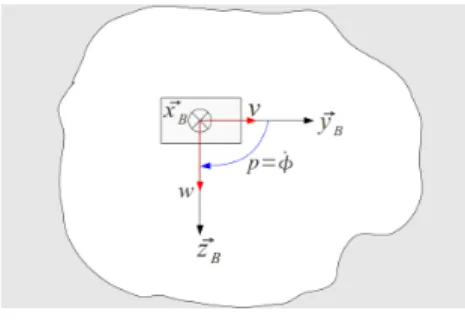
Assumption 2 : Thus we limit our study to the { ~yB, ~zB}
plane bringing the problem back to a 2D problem, as shown in Figure 2, with the karst profile changing through time.
Moreover, as the interaction between the controler pre-sented in Assumption 1 and the DVZ-based centering con-troller is beyond the scope of this paper, we will assume that the other controller has reached its steady state and thus
Fig. 2. The 2D problem statement
r = 0 and q = 0. So we can write the kinematic relation between ˙φ and p as :
˙
φ = p (4)
Assumption 3 : The simplified inverse dynamic model, where the coupling terms are neglected, is :
Fv = mv˙v − dvv (5)
Fw= mww − d˙ ww (6)
Γp= mpp − d˙ pp (7)
where mv, mw and mp are the total masses (dry mass +
added mass or inertia) along each motion axis. dv, dw and
dp are the quadratic damping terms for each motion axis.
We assume that this model is exact (i.e. its parameters are precisely known).
Under these assumptions, the control has two objectives : ensure that the robot reaches the ”center” of the conduit and set its roll, φ, to a desired value φd.
C. Assumptions on the Karst
Finally we have to make a number of assumptions on the karst conduit in order to ensure that the robot can indeed reach the ”center” of the conduit.
Assumption 4: The conduit is filled with water. Thus the AUV can reach the karst ”center”. However, uncertainties related to water currents are neglected in this paper.
Moreover, to be sure that the robot can find this ”center”, it must be able to view the entire conduit outline.
Assumption 5 : The minimal, dminkarst, and maximal,
dmaxkarst, radii of the Karst towards its ”center” should be
such that :
dmincapt < dminkarst< 2 ∗ dmaxkarst < dmaxcapt (8)
Assumption 6 : The robot must always be in the set of points such that the minimal distance of the robot to any walls dminwalls respects the condition :
dmincapt ≤ dminwalls (9)
Assumption 7: Sometimes the karst conduit shape may be very concave (see Figure 3). If there is enough space for the robot to get through a part of the conduit, the sensor will not detect the parts of the conduit that lie beyond the concavity. Thus, from the robot perception, the conduit will be brought back to a shape respecting the previous assumptions.
Thus conduits such as the one presented in Figure 3 will not be considered in simulation and theory.
Fig. 3. A very concave conduit profile
III. THEDVZAND ITS PARAMETERS
A. The DVZ : a representation of the interaction between the robot and its environment
Presented in [9] for obstacle avoidance, the DVZ (De-formable Virtual Zone) is a representation of the interaction between the robot and its environment. The DVZ is a zone, with a chosen geometric shape, surrounding the robot and which moves according to the robot dynamics. The intrusion of an obstacle deforms the DVZ shape. Then the DVZ reacts to this intrusion according to its own virtual dynamics in order to maintain its original shape. The robot control is finally computed to follow the DVZ required movement.
Thus we need to choose the DVZ shape and dynamics. Our DVZ will be a circle of radius RDV Z. The DVZ dynamics is
chosen so that the control along the robot’s motions axes will behave like a mass-spring-damper system. Its well-known equation is :
m¨a = −Ka − c ˙a (10) where a represents the displacement of m along the ~aS axis.
The idea of using a force generated by a spring-like system was also proposed in [10] where impedance control uses a force generated by the robot-obstacle distance to compute the control required to avoid obstacles. However, thanks to the DVZ approach, we can use explicitly the mass-spring-damper equation in the control algorithm. This allows us to study in an easier way our system parameters, since they have a physical related meaning and are not abstract coefficients. The DVZ approach allows us a simpler management of the control when the robot is surrounded by obstacles.
B. Modifications to the DVZ
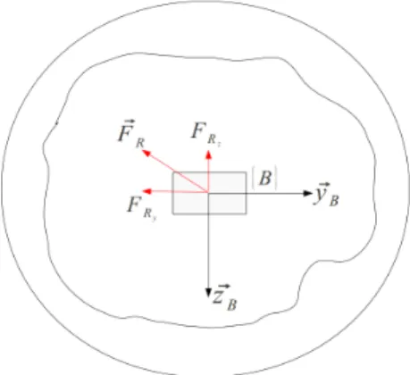
In previous part, we explained that the DVZ reacts to shape deformations by trying to recover its original shape. However, when the DVZ is surrounded by obstacles it cannot recover its shape. This is what happens in the karst. Instead, the DVZ controller will drive the system to reach the point where all the intrusions compensate each other. This point will be such that the force resulting from all the intrusions (see Figure 6), ~FR, is null.
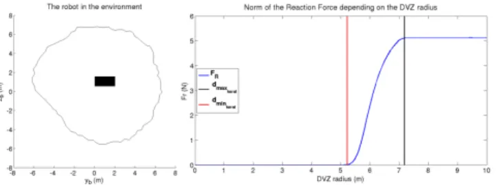
C. Tuning of the DVZ radius
As presented previously, our DVZ behaviour is a circle of radius RDV Z. The intrusion-generated force, shall not
depend on the value of RDV Zbut only on the distance of the
robot to the conduit ”center”. Figure 4 shows the relationship between RDV Z and the intrusion-generated force when the
robot is close to the conduit ”center” as shown in the left
Fig. 4. Relationship between k ~FRk and the DVZ radius
part of the figure. So if the robot is at a distance dmaxkarst
of the center, the force no longer depends of RDV Z when :
RDV Z > 2 ∗ dmaxkarst (11)
Thus due to Assumption 5 we have :
RDV Z= dmaxcapt (12)
IV. CONTROL A. Intrusion and resulting force computation
Fig. 5. Intrusion and force. Let the set of intrusions in the DVZ be :
I = {(~δi, αi) such that k~δik = δi= RDV Z−di, i = 1..NR}
(13) Each intrusion induces a reaction force, ~fi, such that :
~
fi= −KDV Zδ~i (14)
Where KDV Z is a strictly positive spring stiffness which
shall be set up by the designer to get the desired system reponse profile.
The coordinates of this vector in {B} are :
fiy = −KDV Zcos(αi)δi (15)
fiz = −KDV Zsin(αi)δi (16)
The force resulting from all the intrusions is given by : ~ FR= NR X i=1 ~ fi (17)
Its coordinates in {B} are : FRy = −KDV Z NR X i=1 cos(αi)δi (18) FRz = −KDV Z NR X i=1 sin(αi)δi (19)
Fig. 6. Resulting force
B. Control computation
The resulting force ~FR is not null due to the imbalance
between the intrusions. Our aim is to compute the control in order to reach the point where :
~
FR= ~0 (20)
As {B} is an orthonormal frame, this objective becomes :
FRy = 0 (21)
FRz = 0 (22)
Moreover, we want our system to react to those forces like the mass-spring-damper system presented in section III alongside both ~yB and ~zB. We can then write the two first
control equations : ˙vco= FRy mv −cvv mv (23) ˙ wco= FRz mw −cww mw (24) where mvand mware the robot’s total masses (i.e. dry mass
plus added mass) on ~yB and ~zB respectively. cv and cw are
the damping coefficients.
As presented in section II, in addition to reaching the karst ”center”, we want our robot to reach a desired φd. The evolution of the error φd− φ is guided by the first-order differential equation :
( ˙φd− ˙φ) = −K
φ(φd− φ) (25)
where Kφ is a strictly positive parameter which drives the
system response time.
As we set φd as a constant, we obtain from (4) : pd = −Kφ(φ − φd) (26)
Then similarly to (25), we can write : ( ˙pd− ˙p) = −K
p(pd− p) (27)
where Kp is a strictly positive parameter which drives the
system response time.
Thus we obtain the last control equation : ˙
pco= −Kpp − Kr(φ − φd) (28)
with Kr= KpKφ a strictly positive parameter.
Then we feed the desired accelerations ˙vco, ˙wco and ˙pco
in the inverse dynamic model presented in (5), (6) and (7) to compute the forces that should be applied by the robot actuators (with Assumption 3 respected) :
Fvco= mv˙vco− dvv = FRy − (cv+ dv)v (29)
Fwco= mww˙co− dww = FRz− (cw+ dw)w (30)
Γpco= mpp˙co− dpp = −(mpKp+ dp)p − Krmp(φ − φ
d)
(31) C. Damping coefficient setting
We shall now set up our damping coefficients, cv and
cw, to guaranty that our mass-spring-damper will work in a
critical regime in the worst intrusion case. This will guaranty us that no matter how strong the intrusion may be, our system will converge without oscillation or overshooting.
Assuming that NR is even and thanks to the DVZ
sym-metric shape (18) becomes :
FRy = −KDV Z NR 2 X i=1 cos(αi)[δi− δi+NR 2 ] (32) Let us note : ∆ = maxi=1 ..NR 2 [δi− δi+NR 2 ] (33) The worst intrusion case occurs when :
[δi− δi+NR 2
] = ∆ f or all i ∈ [1..NR
2 ] (34) Consequently we can write :
FRy ≤ FRyMax (35) with FRyMax = −KDV Z∆ NR 2 X i=1 cos(αi) (36)
And as cos(αi) ≤ 1 we can write the force in the worst
case of intrusion :
FRyMax < −KDV Z∆
NR
2 (37)
This leads to the computation of cv in order to guarantee
a convergence without oscillation : cv= 2
r
mvKDV Z
NR
2 (38)
Similarly we can write : cw= 2
r
mwKDV Z
NR
2 (39)
Thus our resulting force is assimilated to the force a single spring of stiffness Ke would generate. In the worst
case (Ke = KDV ZN2R), the damping coefficients warrant
convergence in critical regime. And in most cases (Ke <
KDV ZN2R), the generated force will be inferior to the
max-imal force. The system will be over-damped thus preventing any possibility of oscillations or overshooting.
D. Proof of stability
Taking back the notations of [9], we can write the state of our controller as (π, Ξ) with π = (p, v, w, φ) the states related to the robot dynamics and Ξ = (FRy, FRz) the states
related to the interaction of the DVZ with the environment. We shall now prove the stability of our controller, which is an autonomous system. Consider the candidate Lyapunov function, we have to prove that it respects the conditions of Barbalat’s lemma : V = (p − p d)2 2 + 2Kr (φ − φd)2 2 + F2 Ry 2 + Kemv v2 2 +F 2 Rz 2 + Kemw w2 2 > 0 (40) Its derivative is : ˙ V = ( ˙p − ˙pd)(p − pd) + 2K r(φ − φd)( ˙φ − ˙φd) + FRyF˙Ry + Kemv˙vv + FRzF˙Rz+ Kemwww˙ (41) We have : ˙ FRy = −Kev (42) ˙ FRz = −Kew (43) Ke= ηKDV Z such that 0 < η < NR 2 (44) Remembering that ˙φd= 0 and with (27) verified, we can
write from (26), (23), (24) and (4) : ˙
V = −Kpp2− KpKφ2(φ − φd)2− Kecvv2− Kecww2
(45) Thus V˙ < 0. We have proven that V is bounded. Derivating ˙V , we can write :
¨
V = −2Kppp − 2K˙ pKφ2(φ − φ
d)( ˙φ − ˙φd)
− 2Kecvv ˙v − 2Kecww ˙w (46)
From (28), (4), (23) and (24), ¨V becomes : ¨ V = 2Kp2p2+ (φ − φd)p(2KpKr− 2KrKφ) + 2 Kec2v mv v2 − 2Kecv mv vFRy+ 2 Kec2w mw w2− 2Kecw mw wFRz (47)
As V is bounded this means p, (φ − φd), v, w, FRy and
FRz are bounded. Thus ¨V is bounded.
We have proven that V > 0, ˙V < 0 and ¨V is bounded. We can use Barbalat’s lemma [11] and say that our control is Globally Uniformly Assimptotically Stable.
V. SIMULATION RESULTS A. Simulation parameters
We are here listing the value of the differents parameters shared by the two simulations presented below.
The robot moves with u = 0.5 m/s. We are using a profilometry sonar whose parameters are : Tc = 1 s,
dmaxcapt = 15 m, dmincapt = 0.1 m and NR = 100. The
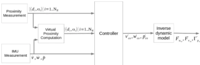
Fig. 7. Controller and sensors synoptic. The computation of v, w, p and φ by integration of the measured accelerations is made in the controller.
robot speeds and angle are computed using an IMU of sampling time TIM U = 0.1 s.
Our control loop has a period of 0.1s. This means that in between two sonar measurements, we must create a virtual measurement from the latest proximity measurement and the current estimated robot position (obtained from integration of the IMU measurements) as shown in Figure 7.
For both simulations, We have set mv = mw = 15 kg,
mp = 1 kg and dv = dw = dp = −1. The three designer
defined parameters, KDV Z, Kr and Kp have the value :
KDV Z = 0.8, Kr= 2 and Kp= 4. Finally, φd= 0.
B. Pipe simulation
Our first simulation example is a regular pipe made of four cylinders as shown in Figure 8. This environment will allow us to demonstrate the convergence properties of our system.
Fig. 8. First Simulation Environment : A pipe made of four cylinders of different radii and center coordinates.
The Figure 9 presents the evolution of the robot pose. In the two upper figures, as expected from the pipe reg-ular shape, the robot converges to the center of the pipe. Moreover, as shown by the lower right figure, FRy and FRz
converges to 0 as expected. Finally the lower left picture illustrates the convergence of φ towards φd= 0.
The Figure 10 presents the forces generated by the control activity. They have values compatible with the forces our real system (the Jack, c Ciscrea) could generate.
Fig. 10. Actuation activity in the pipe environment simulation
C. Karst environment simulation
The second simulation uses the karstic environment pre-sented in Figure 11.
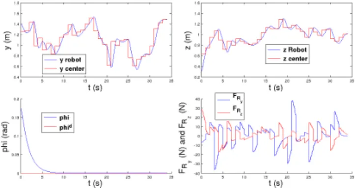
Fig. 11. Karstic environment
In the two upper figures of Figure 12, we see that our system tracks the measurement ”center” but cannot converge because the environement is evolving too quickly. And as one can see on the lower right figure, FRy and FRz also
don’t reach 0 but they clearly evolve towards 0 after the environment changes.
Fig. 12. Pose, FRy, FRzevolution in the Karstic environment simulation
The Figure 13 presents the forces generated by the robot’s actuation system which are still realistic.
Fig. 13. Actuation activity in the Karstic environment simulation
VI. CONCLUSION AND FUTURE WORK
In this paper, we have presented a new control algorithm allowing an AUV to center reactively in a conduit of a karstic aquifer. It is based on the DVZ principle and allows our dynamic system to behave like a mass-spring-damper system. Moreover, it requires the user to set up only three control parameters. We have proven the stability of such a controller. Simulations have demonstrated the good convergence and dynamic abilities of our controller in regularly or irregularly shaped environments. We should now study the robustness of our controller to modelling uncertainties, sensor noise and environmental disturbances. We should also study the inter-action between this control algorithm and the one presented in Assumption 1. Finally we will try to relax Assumption 5.
VII. ACKNOWLEDGEMENTS
The authors would like to thank the French labex NUMEV for supporting this research.
REFERENCES
[1] N. Dorfliger, H. Jourde, B. Ladouche, P. Fleurry, P. Lachassagne, Y. Conroux, S. Pistre, and A.Vestier, “Active water management resources of karstic water catchment: the example of le lez spring,” in World Water Congress, 2008.
[2] M. Bakalowicz, “Karst groudwater : a challenge for new ressources,” Journal of Hydrogeology, pp. 13: 148–160, 2005.
[3] O. Tatar and D. Mandru, “Robotic systems for inspection and explo-ration,” Annals of the Oradea University. Fascicule of Management and Technological Engineering, vol. VII (XVII), 2008.
[4] R. Bradbeer, S. Harrold, F. Nickols, and L. Yeung, “An underwater robot for pipe inspection,” in Proceedings of 4th International Con-ference on Mechatronics and Machine Vision in Practice, (M2VIP97), 1997, pp. 152–156.
[5] T. Saitho, N. Tada, and R. Konishi, “Indoor mobile robot navigation by center following based on monocular vision,” in Computer Vision, X. Zhihui, Ed. InTech, 2008, ch. 20, pp. 351–366.
[6] R. Carelli and E. O. Freire, “Corridor navigation and wall-following stable control for sonar-based mobile robots,” Robotics and Au-tonomous Systems, no. 45, 2003.
[7] A. K. Simpson, “Autonomous robot control for underwater tunnel mapping,” Senior thesis, Princetown University, 2012.
[8] L. Yingxue, “Autonomous control for remotely operated vehicles,” Senior thesis, Princetown University, 2012.
[9] R. Zapata and P. Lepinay, “Fast mobile robots in unstructured envi-ronments,” Lecture Notes in Computer Science, vol. 708, pp. 94–105, 1993.
[10] R. Carelli, H. Secchi, and V. Mut, “Algorithms for stable control of mobile robots with obstacle avoidance,” Latin America Applied Research, vol. 29, pp. 191–196, 1999.