HAL Id: hal-01631559
https://hal.archives-ouvertes.fr/hal-01631559
Submitted on 9 Nov 2017HAL is a multi-disciplinary open access archive for the deposit and dissemination of sci-entific research documents, whether they are
pub-L’archive ouverte pluridisciplinaire HAL, est destinée au dépôt et à la diffusion de documents scientifiques de niveau recherche, publiés ou non,
Behavior of pre-cracked deep beams with composite
materials repairs
M Boumaaza, A. Bezazi, H Bouchelaghem, N Benzennache, Sofiane Amziane,
F. Scarpa
To cite this version:
M Boumaaza, A. Bezazi, H Bouchelaghem, N Benzennache, Sofiane Amziane, et al.. Behavior of pre-cracked deep beams with composite materials repairs. Structural Engineering and Mechanics, Techno-press Ltd, 2017, 63 (5), pp.575-583. �10.12989/sem.2017.63.5.575�. �hal-01631559�
Behavior of pre-cracked deep beams with composite materials
repairs
M. Boumaaza
1, A. Bezazi
2, H. Bouchelaghem,
2,3,
N. Benzennache
1, S. Amziane
*4, F. Scarpa
*5 1Laboratoire de Génie Civil & Hydraulique (LGCH), Université 8 Mai 1945 Guelma, BP 401 Guelma 24000, Algérie. [email protected] [email protected]
2
Laboratoire de Mécanique appliquée des nouveaux matériaux (LMANM), Université 8 Mai 1945 Guelma, BP 401 Guelma 24000, Algérie
3
Département de Génie Mécanique, Université de Constantine 1, Algérie. [email protected]
4
Département, Génie Civil Polytech Clermont Ferrand Université Blaise Pascal, UMR 6602, Institut Pascal BP 206, 63174 Aubière, France.5 [email protected]
5
Advanced Composites Centre for innovation and Science (ACCIS), University of Bristol, BSB 1 TR Bristol, UK. [email protected]
(Received as blank , Revised keep as blank , Accepted keep as blank )
Abstract. The study covers the behavior of reinforced concrete deep beams loaded under 4-point bending, failed by shear and repaired using bonding glass fiber reinforced plastics fabrics (GFRP) patches. Two rehabilitation methods have been used to highlight the influence of the composite on the ultimate strength of the beams and their failure modes. In the first series of trials the work has been focused on the reinforcement/rehabilitation of the beam by following the continuous configuration of the FRP fabric. The patch with a U-shape did not provide satisfactory results because this reinforcement strategy does not allow to increase the ultimate strength or to avoid the abrupt shear failure mode. A second methodology of rehabilitation/reinforcement has been developed in the form of SCR (Strips of Critical Region), in which the composite materials reinforcements are positioned to band the inclined cracks (shear) caused by the shear force. The results obtained by using this method lead a superior out come in terms of ultimate strength and change of the failure mode from abrupt shearing to ductile bending.
Keywords: glass fiber; shear reinforcement; reinforced concrete; beams; repair; failure modes; cracking
1. Introduction
The maintenance and repair of civil engineering structures involves problems both in terms of structural integrity and performance, as well as cost effectiveness and durability of these structures. In this context, the development of suitable repair techniques constitutes a major challenge for the building industry. The deterioration of the structures due to the decrease of the material mechanical properties requires the development of new rehabilitation techniques and a good control of the behavior of the material constituents.
Many reasons can justify the use of reinforcements or repairs. Between the various technical causes that justify the adoption of rehabilitation techniques one can cite examples such as structural alterations and changes of use or even repairs after earthquakes. Initially, steel plates bonded to the concrete elements were used as reinforcing components, but they have been gradually replaced by the use of composite materials. Composites constitute a very attractive solution to answer the need for reinforcement in buildings and civil engineering structures. As the cost of the structural repair by using composite materials based on carbon fibers is not negligible, the industrial application of the repair technique by including glass fibers or hybrids could be a viable alternative to be considered from a design perspective (Attari et al. (2012)).
In recent years many research activities and practical realizations of external reinforcements using composite materials have been developed. The behavior of reinforced concrete deep beams (a/d=1.3)
where a is the free range and d the depth
witch fail by shear and are then strengthened or repaired has been the subject of a limited number of research papers. It must be noted that the shear behavior of steel reinforced concrete beams is an already complex topic, because a multitude of parameters often interdependent influence the mechanical behavior of the structural elements. An example of the set of these interrelated parameters is the geometry of the type of the structural component considered (deep or slender beam type, longitudinal steel ratio, beams size and the rate of transverse reinforcement etc ...). Moreover, different failure modes are observed for reinforced concrete beams by (Chajes et al. 1994 Chaallal et al. 2002 Diagana et al., 2003, Zhang and Hsu 2004). Recently, Ramadass and Thomas (2015) have identified the major influential parameters related to the shear reinforcement using FRP, which are the concrete compressive strength and the longitudinal reinforcement ratio.Several reinforcement methods using composite materials have been used so far, in particular the external bonding (EB) of the FRP fabrics (Ta¨ljstena and Elfgrena 2000 Mofidi and Chaalal 2011, Dong et al. 2013, Manos et al. 2014, Panigrahi et al.2014, Baggio et al. 2014) and the NSMR method (Near Surface Mounted Rebar) the method Near Surface Mounted Rebar (NSMR) by (Lorenzis and Teng 2007, Rizzo and Lorenzis 2009) which consists in bonding bars of FRP near the surface. The ETS method (Embedded Through Section) The method Embedded Through Section (ETS) developed by (Chaalal et al.2011b and Breveglieri et al. 2014) involves the use of an adhesive for bonding the FRP bars with concrete, and has showed quite satisfactory results in terms of shear strength, especially when no transverse reinforcement was present.
However, a limited set of data related to the behavior of pre-cracked beams repaired with composite materials and subjected to static 4-point bending loading is available in open literature, and this is the main rationale behind the scope of this work. The problem of deep beams failed by shear is at the core of the research activities presented in this paper, together with the repair or rehabilitation of the shear damaged structure by compensating the loss of rigidity and strength, which ultimately leads to extend the life and durability of the structure.
A current important challenge is to find approaches that mitigate the catastrophic failure mode by shear existing in reinforced concrete deep beams. In order to solve this problem, a new method based on the use of bands in critical regions SCR (Strips of Critical Region) is being proposed in this work. This proposed rehabilitation technique is feasible, efficient and shows that the performance of the repaired beams is significantly higher compared to other shear repair approaches based on EB classical methods. The proposed method constitutes an innovative alternative, potentially more effective and leads to the desired failure mode by bending, rather than shearing.
2.Experimental protocol
2.1 Preparation ofthe test specimens and test conditions
The experimental tests have been carried out on deep beams whose ratio between the distance of between the application of the point loads and the support at the height of the beam is small (only 1.3) so that shear failure is predominantly. These investigations are useful to identify the contribution of the GFRP in terms of strength gain and failure modes. The tests were conducted in accordance with the ASTM C78-00 (2004) using a four-point bending device with a capacity of 150 kN (Fig. 1 (a)).
The manufacturing of the beams was performed at the Laboratory of Civil Engineering and Hydraulics (LGCH) of Guelma University. In order to characterize the compressive strength In order to characterize the concrete, six cylindrical and cubic specimens having dimensions of 160x320 and 150x150 mm2 respectively were also produced. After 24 hours the specimens are removed from the mould and stored in tanks of water at ambient temperature up to 28 days. The beams have 730 mm long and width and height of 100 mm and 180 mm respectively, they are reinforced by two HA8 bars in the tensioned zone and by two HA6 bars in the compressed one. For vertical steel (steel frames), 6 mmof diameter rods in mild steel and spaced by 110 mm have been used (Fig.1 (b)-(d)).
(a)Machine test
(b)pouring of concrete (c) Strengthening with armatures
(d) Detail of the beam
Fig 1 characteristics of the beams tested
Table 1 shows the configurations adopted for this study, with the codes of the twelve reinforced concrete beams fabricated under the same conditions. The first three are control beams, six are sane (not preloaded) and strengthened by two and three plies of GFRP with U shape. The last three beams are preloaded at 40% of their ultimate strength; two are repaired by two and three plies of U-shaped GFRP, while the last one with the proposed new SCR method by bonding on the beam failure region.
Table 1: Identification of the strengthening configurations
Specimen Type strengthening
Series A No preloaded DB_control -- DB_NP_(0/90)_STV1 1 ply with GFRP DB_NP_(20/70)_STV1 1 ply with GFRP DB_NP_(30/60)_STV1 1 ply with GFRP DB_NP_(+45/-45)_STV1 1 ply with GFRP DB_NP_2c_STV1 2plies with GFRP DB_NP_3c_STV1 3 plies with GFRP preloaded at 40% DB_40%_2c_STV1 2 plies with GFRP DB_40%_3c_STV1 3 plies with GFRP Series B preloaded at 40% DB_40%_STV2 Strips of Critical
Region (SCR)
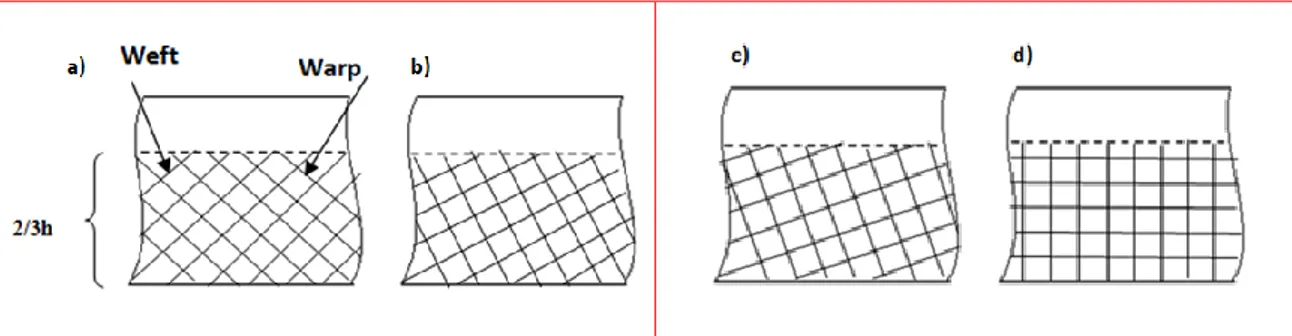
To better understand the behaviour of the reinforced concrete beams preloaded and repaired by glass bidirectional fiber fabrics (GFRP), a testing program was established by using two specific rehabilitation methods. The activities related to the first series of tests have focused on strengthening or repairing by using a continuous configuration of the reinforcement consisting in GFRP with a U-shaped recovery system following orientations (0/90, 20/70, 30/60 et +45/-45) (Fig. 2).
Fig. 2 Reinforcement with U shape patch following orientations a) +45/-45 b) 30/60 c)20/70 d) 0/90.
The second series of tests consists in placing reinforcements made from composite materials according to the new proposed procedure. The composite patches are placed as to intersect the cracks produced by the shear force in order to improve the brittle failure mode of the reinforced concrete. In this way the glass fibers of the composite are loaded along their longitudinal direction (tensile) and therefore maximizing the strength of the system. This method uses a composite constituted by strands of unidirectional glass fibers impregnated in polyester resin and applied as a wrapping system on the beam by bonding.
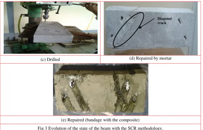
After drilling the holes the damaged beams have been repaired using mortar concrete. This repair was performed in order to improve the aesthetics and the surface finish before the bonding of the composites (see Fig. 3 (d) and (e)). The various reinforcements were arranged to intercept the diagonal cracks as accurately as possible. To facilitate the setting of the unidirectional fabric with the resin in the holes, the fibers are interlaced and centered in each hole. It is necessary that the holes are very clean before the resin filling. As the load is symmetric, it is important to note that the non-cracked parts of the beam are also repaired in the same manner to avoid the appearance of new diagonal cracks.
(c) Drilled (d) Repaired by mortar
(e) Repaired (bandage with the composite)
Fig 3 Evolution of the state of the beam with the SCR methodology.
2.2 Characteristics of the materials 2.2.1 Glass fiber
The composite materials used in this study belong to two series:
Series A: the composite patch STV1 is made from bidirectional glass fiber having a surface density of 500 g/m2 with U-shaped recovery system according to different orientations (0/90, 20/70, 30/60 and +45/-45). The total mass of the fiber reinforcement is 102 g all manually impregnated into a polyester resin with rollers (low pressure) to ensure complete bonding between the concrete and the GFRP and avoid trapped air bubbles. The configuration of the composite STV1 is U-shaped continuously applied for a length of 580mm and a height of 120mm (2 / 3h).
• Series B: the STV2 patches consist of 15 strands of glass fibers in the shear zone of the cross section of the reinforced concrete beam, taken from the same fabric STV1, with a total mass of the reinforcement of 40 g and a polyester resin.
The beams were let to cure at room conditions for at least two weeks before being tested. The repaired/reinforced beams were let to cure at room temperature at least two weeks, in order to have a total polymerization of the resin, before being tested.
2.2.2 Concrete and steel
The average compressive strength of 28 MPa of the concrete is determined from using three cylindrical specimens after 28 days. These specimens were made from the same cast as used for the fabrication in accordance with the ASTM C39-96 standard. The yield strengths of the steel bars and steel stirrups are 400 and 240 MPa, respectively. The main characteristics of concrete, steel, resin, fabric Series A and the Series B are summarized in Table 2.
Table 2. Characteristics of the materials used
Diagonal crack
Material Young's modulus (GPa) Limited to tensile failure fr (MPa) Concrete 23.9±0.95 28±2.2 Steel HA 200 400 Steel soft 200 235 Resin (flexural) 3.33±0.25 81.74 ±11.08 Resin (tension) 12.13±2.04 29.36 ±2.87
Glass fiber (Series A)
8.5 171
Glass fiber (Series B) 40%
31.2 1377
Glass fiber (Series B) 33%
26.3 1141
3. Results and discussions
The experimental results are presented in the following sections in terms of failure load, ductility of the beams and the observed failure modes.
3.1 Influence of the compositeSTV1 orientations
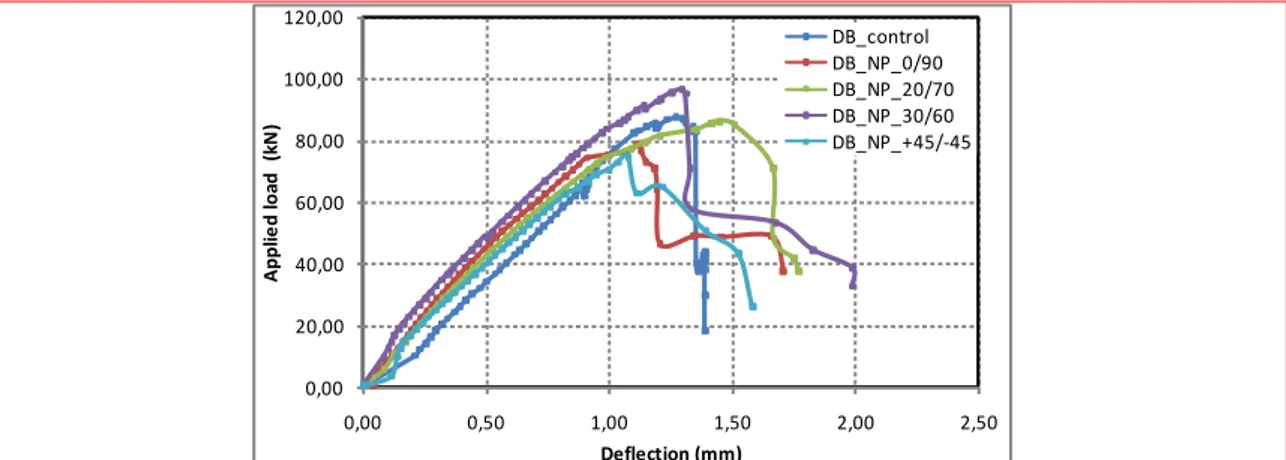
The results obtained show that the stiffness of the beams is increased by the bonding of the composite patch. The best performance is obtained for the beam reinforced with the stacking of (+30/-60) (see Fig. 4).The ultimate strength of the control beam is 87.6kN with a deflection equal to 1.27 mm. Based on the orientation of the reinforcement, the ultimate load of the beam (DB_NP_30 / 60) is increased by 10.5% compared to the reference beam (DB_control). This gain at the ultimate load is accompanied by a reduction in ductility, resulting in a decrease of the deflection by approximately 12.4% compared to the beam (DB_NP_20 / 70). This value is in good agreement with the results obtained by Bouchelaghem et al. (2011 a, b) for cylindrical specimens. The beams have diagonal cracks having an average orientation 34 °. The orientation of the composite fibers should be perpendicular to the cracks in order to sew them. The solicitation in the composite of the beam (DB_NP_30 / 60) presents a lesser shear effect as that of the beam (DB_NP_20 / 70) due to the difference of the directions respectively which is in the order of 4 and 14 ° to the direction of the crack (34 °) obtained experimentally after preloading. This is why the beam (DB_NP_30/60) has a higher ultimate strength compared to the beam (DB_NP_20/70).
The orientation of the fibers has a great influence on the behavior of test pieces due to the difference in rigidity which characterizes the first phase of the curves.
Because of this reason, the (+30/-60) orientation is adopted in the following steps of this work, i.e. all other beams of the series A were repaired using the external bonding with two or three plies of GFRP and only using the (+30/-60) orientation.
0,00 20,00 40,00 60,00 80,00 100,00 120,00 0,00 0,50 1,00 1,50 2,00 2,50 A pp lie d loa d (k N ) Deflection (mm) DB_control DB_NP_0/90 DB_NP_20/70 DB_NP_30/60 DB_NP_+45/-45
Fig. 4 Force-deflection curves of non preloaded beams obtained for the orientations (0/90,20/70,30/60 and +45/-45)
3.2 Influence on stiffness and strength provided by the number of plies in the composite U-shaped STV1 patches
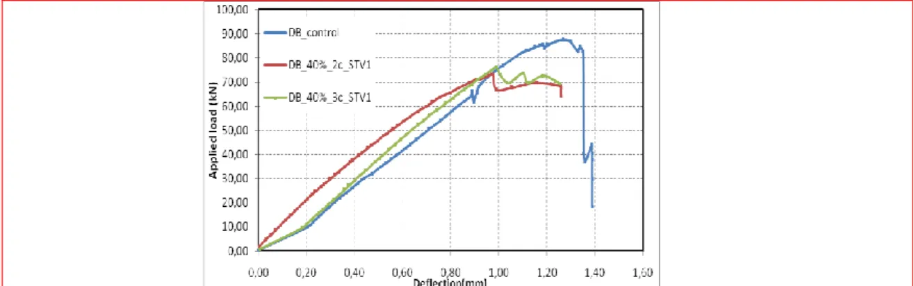
The beams considered in this case belong to the non-preloaded and preloaded cases reinforced with the composite STV1 patches with different thicknesses. Figure 5 shows the load history of the non-preloaded reinforced beams with one, two and three composite plies compared to the analogous behavior of the control beam.
The load drop occurring on the curves of figure 5 shows a sudden drop in resistance due to delamination of the composite. The analysis of the results shows that the rate of improvement of the ultimate strength of the beams reinforced by one ply is in the order of 10.5% compared to a control beam, whereas the application of one or two plies of the fabric PRFG leads to decreases in strength in the order of 12.5 and 27.6% respectively. The strengthening of deep beams appears therefore to be governed by the first ply only, and this is in good agreement with previous works from (Bousselham and Chaallal 2006 Contamine et al. 2013). It was also noticed that the beams bonded by three layers of STV1 show a more stable deflection behavior compared to the case of beams strengthened by one and two layers. The beams reinforced by one and three plies showed however a greater stiffness than the control beam (Sundarraja and Ganesh Prabhu 2011). In addition, it was observed that the beam reinforced by a ply STV1 showed a greater rigidity than the control beam and the beams reinforced by two and three plies which confirms the work of (Kreit 2012). The absence of bearings in the test setup explains the brittle behavior of the deep beams.
Fig. 5 Force/deflection curves of STV1 reinforced non-preloaded beams.
The load corresponding to the appearance of diagonal cracks is in the vicinity of 40% of the ultimate load, and therefore it appears reasonable to use this value for the preloading of the beams. The responses of the beams at this level of preloading and then repaired by two or three plies of composite
with U shape are shown in Fig. 6. The preloaded and then repaired beams using one or two plies showed a less brittle behavior, with a reduction of the resistance respectively in the order of 15.3 and 12.3% ,76% and 78% for deflection respectively for specimens repaired by two and three plies and a stiffness increase compared to the control beam. These beams still show some residual compliance that provides lower brittleness compared to the control beam. The composite repairs do not appear however to provide a significant influence to the resistance of the beams.
T
he resistance of the beam (DB-40% -3c-STV1) is greater than the resistance of the beam (DB - 3c-NP) due to the deformations of the most remote zones of compression concrete which have reached their limits near the loading area after the crushing of the concrete compression (Figs. 4, 5 and 6).Preloaded beams then repaired by U-shaped composite STV1 showed a higher rigidity than that of the control beam. The STV1 reinforcing with U-shape does not prevent diagonal cracks to appear.Fig. 6 Force/displacement curves charge / deflection of the beams preloaded at 40% of the ultimate load and then repaired by the STV1 patch.
3.3 Effect of the SCR method on the strength and stiffness of the beams when using the STV2 patch
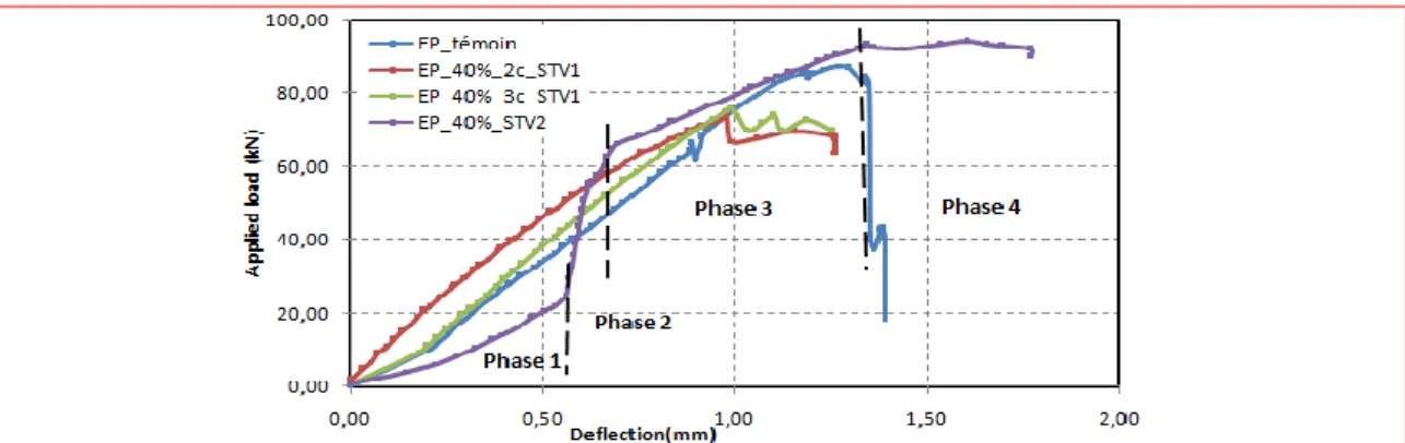
The analysis of the results obtained on the beam preloaded at 40% of its ultimate load and then repaired following the new SCR method (wrapping in the cracked zone) using the composite STV2 (DB_40%_STV2) allowed an increase of the load capacity of 7.1% and a more ductile behavior with an increase in the deflection of the order of 26% compared to the control concrete beam as shown in (Fig. 7).The load deflection behavior of this beam is quite different from the others and can be divided into four phases. During the first part of the curve it is possible to notice a, nonlinear elastic behavior
nonlinear behavior dominated by the concrete until a load of 25 kN, Phase 1 represent the concrete behavior which its rigidity has decreased significantly due to the cracked concrete for the preloaded beam (EP_40%_STV2) comparatively of the other tested beams followed by a very significant increase of the stiffness (increase in the slope) in the second phase until a value of 67 kN. The stiffness increase is due to the contribution of the composite patch that possesses very good tensile properties. During the third phase the curve segment is equivalent to the other curves with a slight higher increase due to the significant contribution of the composite to the resistance to shearing forces, which is characterized by a drop in stiffness followed by a quasi-plateau in the fourth phase. The latter behavior can be explained by the appearance of vertical cracks and a sudden shear failure mode caused by the shear force, by a ductile one by bending, and therefore leading to failure mode change from brutal due to the shear to a ductile one due to bending.
Fig. 7 Force/deflection curves of the beams preloaded at 40% and repaired with U-shaped and SCR.
Table 3 lists the loads attained at failure for the two repair types, namely the U-shaped one (with 2 and 3 plies) and the SCR approach. The table lists the type of composite, the gain or loss of load capacity, defined as [1- (load after repair / load of control concrete)] × 100%, and a summary of the final failure type for each beam. Beams rehabilitated with composites having a U-shape with two and three plies use 74% and 143% more composite material respectively, compared to the new SCR method proposed. The results of the tests are very positive with an increase of 7.1% and 26% of the ultimate load and deflection of the rehabilitated SCR beams compared to the beam control, while the rehabilitated beams by the patches (two and three plies) with U-shape bring reductions of 16.1% and 13.1% .for the ultimate load, and 23% and 22% for the deflection.
Table 2. Load capacity gain or loss and failure mode types for the studied beams. Table 3. Load capacity and failure mode types of tested beams.
Beam types (U/SCR)* Ultimate load (kN) Gain or loss of ultimate load (%) Deflection (mm) Gain or loss of deflection (%) Failure mode DB_control ---- 87.6 ---- 1.27 ---- Shear DB_40%_2_STV1 1.74 73,52 -16.1 0.98 -23 Shear+debonding DB_40%_3_STV1 2.43 76,17 -13.1 0.99 -22 Debonding+crushing of concrete compressive DB_STV2 1 94,33 +7.1 1.60 +26 Bending
* Quantity of the used composite / composite SCR.
3.4 Cracking and failure modes of the beams reinforced/repaired using the STV1 patch
Figure 8 shows that the control beam subjected to 4-point bending underwent shear failure. The reasons behind the particular failure type are two folds:
The average ultimate strength of the beam is 86.7 kN. This value corresponds approximately to the one estimated by using the BAEL 91 code (84.5 kN). The average ultimate strength of the beam obtained experimentally is 86.7 kN, which this value is very close to 84.5 kN estimated by using the BAEL 91 code. The failure of the control beam due to oblique principal stress was planned because the estimated ultimate strength due to bending is 27% higher than the estimated one with shear force (61.7 kN). In addition, the slenderness ratio of the beam is equal to (a / d = 1.3), which is an appropriate geometry for a beam with the type of failure experimentally found.
The ultimate strength VEd of the shear force with the reinforced elements and calculated by using Eurocode 2(VEd = VRd, c + VRd, s) is in the order of 61 kN, whereas the calculated value of the maximum shearwhereas the characteristic value of the maximum shear force calculated VRd, max is in the order of 83 kN. This level of force can be taken up by the element before the crushing of compression rods (Hamrat et al. 2012). Because VEd<VRd,max we can safely state that the failure is due to transverse reinforcement (shear), and it is not caused by the compression rods.
The parallel diagonal cracks created in the vicinity of the supports are located around the position of the application of the point load, and may appear on both sides and propagate with increasing load values at an angle of approximately 40o. Only the large and dominant crack progresses to reach the application point of the concentrated load where the failure of the beam is obtained only in one side. This behavior is typical of deep beams and also in good agreement with previous works carried out on beams with different and large sizes (Sayed 2014, Baggio 2014 et al.et Bousselham et al. 2006).
Fig. 8 Failure mode of the control beam.
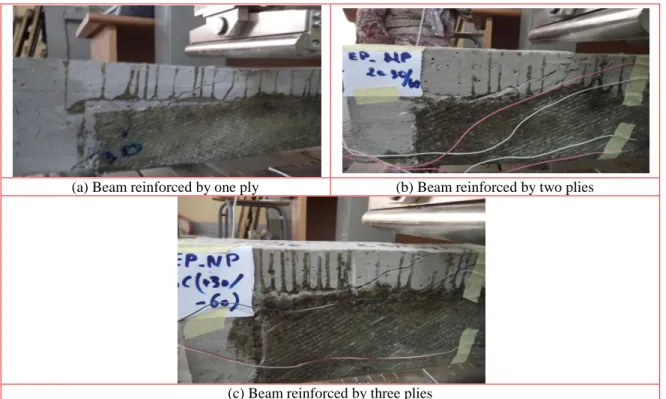
The failure mode observed in the case of the beams non-preloaded and reinforced with one, two or three composites plies of U-shaped patches was shear failure, similar to the one found in the control beam. During the tests one crack was heard followed by the delamination of the composite. In beams reinforced by one and two plies two cracks there after appeared, however only a single crack was evident for the beam reinforced by three plies due to the amount of composites is rather large (Figs. 9 (a) - (c)). Shear cracks could be observed in the part of the beam covered by the composite with the U-shape.
(a) Beam reinforced by one ply (b) Beam reinforced by two plies
(c) Beam reinforced by three plies
mass a delamination between the composite and the concrete in the horizontal and vertical direction was obtained (Figs.10(b)-(c)), followed by the deformations on the concrete in highly compressed zones that have reached their limits near to the loading point (Fig. 10 (d)).
(a) Repaired by two plies (b) Repaired by three plies
(c) Vertical and horizontal debonding (d) Crushing of the concrete under compression Fig. 10failure modes of preloaded beams at 40% and repaired by STV1
3.5 Cracking and failure mode of the beam repaired using the STV2 patch
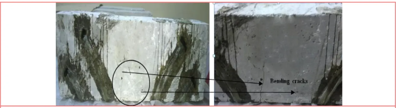
The beam belonging to the B series preloaded and then repaired using the STV2 composite failed by bending due to the appearance of vertical cracks following the formation of a bearing, therefore preventing the shear crack to appear and to develop. The experimental results of the SCR-rehabilitated beam have therefore showed the desired type of failure mode, which is the bending one (Fig. 9).Similar results were also observed by other researchers in previous investigations of reinforced concrete beams strengthened with composite materials using the ETS method by inserting FRP rods into the shear zone of the beam (Chaallal et al . 2011b, Breveglieri et al.2014, Mofidi and Chaallal 2014).Therefore the repair of the beams by bonding with U-shaped continuous fabric does not allow to "sew" the cracks. This is explained by the fact that the series B where the composite is subjected until its rupture, however in the series A the appearance of the delamination (composite/concrete) which does not permit to reach the ultimate strength of the composite. In addition, in the new method (SCR) the strands are continue for few turns banding the cracks, however in the U-shaped (EB), the composite is bonded in the surface only. The SCR method permit to don’t have the delamination
problem by the use of adequate fiber orientation (perpendicular to shear cracks), leading to tensile in the fiber direction, permitting a maximal resistance and then a rational use of the composite until its ultimate strength. Strengthening or repairing the beams using the new method has leads to change the failure mode from a fragile rupture by shear to a ductile one by bending..
Fig. 9 Failure mode of the beam repaired using the STV2 patch.
4. Conclusions
The main objective of this research consisted in developing and improving the knowledge surrounding the alleviation of shear-induced failure by using PRFG to strengthen or repair beams following the newly proposed SCR method. Special focus was dedicated to reinforced concrete deep beams. Composite materials are used to restore and increase the ultimate shear capacity of the beams. The main conclusions are summarized as follows:
The reinforced concrete deep beams subjected to 4-points bending loading fail by shear; The repair or reinforcement of beams by one or two plies of composite STVI patches with a
U-shape led to a shear failure mode like the one already observed in the case of the control beams;
The reinforcement by using one ply of composite U-shaped patch results in an increase of about 10.5% of the ultimate strength. When using two and three plies the ultimate strength decreased by12.5% and 27.6% respectively.
Repair of preloaded beams with STV1 U-shaped composite patches using two and three plies showed reductions ofthe strength in the order of 16.1% and 13.1%, respectively. The failure mode was modified from shear to a concrete compression crushing one when the beam was repaired using three plies;
The beam repaired following the proposed new SCR methodology uses less composite (i.e., lower costs), allows to a diagonal bandage of the crack andleads to increases in the load capacity and deflection of 7.1% and 26% respectively when compared against to the pristine control concrete beam. In addition, this method has changed the final failure mode of the beam from a shear to a ductile one by bending.
Acknowledgments
The authors would like to acknowledge the Ministry of Higher Education and Scientific Research (MESRS) via the project CNEPRU developed at the University of Guelma (J0301520140020).
References
ACI 440.2R-02, (2002). Guide for design and construction of externally bonded FRP systems for strengthening concrete structure.
Alex Li, Cheikhna Diagana, Yves Delmas, (2001), “CRFP contribution to shear capacity of strengthened RC beams”,Engineering Structures, 23(3) 1212–1220
American Society for testing and Materials, (2004), Annual book of ASTM standards, ASTM Publications,
Danvers, USA.
Construction and Building Materials, 66, 634–644.
Barros J.A.O., Dias S.J.E., (2006), “Near surface mounted CFRP laminates for shear strengthening of concrete beams”, Cement Concrete Composite, 28, (3), 276-292.
Bouchelaghem H., Bezazi A., Scarpa F., (2011a), “Compressive behaviour of concrete cylindrical FRP-confined columns subjected to a new sequential loading technique”, Composites: Part B, 42(7), 1987-1993.
Bouchelaghem H., Bezazi A., Scarpa F., (2011b), “Strength of concrete columns externally wrapped with composites under compressive static loading”, Journal of Reinforced Plastics and Composites, 30(19), 1671-1688.
Bousselham A., Challal O., (2006), “Effect of transverse steel and shear span on the performance of RC beams strengthened in shear with CFRP”, Composites Part B: Engineering, 37, 37-46.
Breveglieri M., Aprile A., Barros J.A.O., (2014), “Shear strengthening of reinforced concrete beams strengthened using embedded through section steel bars”, Engineering Structures, 81, 76-87.
Chaallal O., Shahawy M., Hassan M., (2002), “Performance of reinforced concrete Tgirders strengthened in shear with CFRP fabrics”, ACI Struct, 99, 335-343.
Chajes M.J., Januszka T.F., Mertz R., Thomson T.A., Finch W.W., (1995), “Shear strengthening of reinforced concrete beams using externally applied composite fabrics”, ACI Structural Journal, May-June 1995, pp295-302.
Chen J.T., Teng J.G., (2001) “A shear strength model for FRP—strengthened RC beams”, Proceedings of FRPRCS-5, Cambridge, UK, 97-106.
FIB bulletin 14, (2001). Externally bonded reinforcement for RC structures- technicals report design and externally bonded fibre reinforced polymer reinforcement (FRP EBR) for reinforcement concrete structures.
Hamrat M., BoulekbacheB., Chemrouk M., Amziane S., (2012),“Effects of the Transverse Reinforcement on the Shear Behaviour of High Strength Concrete Beams”, Advances in Structural Engineering, 15 (8), 1291-1306.
Kreit A., (2012), “Prolongation de la durée de vie des ouvrages en béton armé”, Toulouse, France: INSA Département Génie Civil.
Mofidi A., Chaallal O., (2014), “Tests and Design Provisions for Reinforced-Concrete Beams Strengthened in Shear Using FRP Sheets and Strips”, International Journal of Concrete Structures and Materials 8, (2), 117-128.
Chajes MJ., Thomson T.A., Januszka TF., Finch Jr., (1994), “Flexural strengthening of concrete beams using externally bonded composite materials”, Construction and Building Materials , 8, (3),191-201.
Dong J, Wang Q, Guan Z., (2013), “Structural behaviour of RC beams with external flexural and flexural–shear strengthening by FRP sheets”, Composites: Part B,44, (1), 604-612.
El-Sayed A K., (2014), “Effect of longitudinal CFRP strengthening on the shear resistance of reinforced concrete beams”,Composites: Part B, 58, 422–429.
Eurocode 2,. (1992), “Design of concrete structures-Part 1-1: General rules and rules for buildings”, ENV 1992 1-1
Lorenzis De.,. Teng J.G., “Near-surface mounted FRP reinforcement: An emerging technique for strengthening structures”, (2007), Composites: Part B, 38, 119-143.
Manos G.C., Theofanous M., Katakalos K., (2014), “Numerical simulation of the shear behaviour of reinforced concrete rectangular beam specimens with or without FRP-strip shear reinforcement”, Advances in
Engineering Software, 67, 47–56.
Mofidi A., Chaallal O., (2014), “Tests and Design Provisions for Reinforced-Concrete Beams Strengthened in Shear Using FRP Sheets and Strips”, Concrete Structures and Materials, 8, (2), 117-128.
Mofidi A., Chaallal O., M. ASCE, (2011), “Shear Strengthening of RC Beams with EB FRP: Influencing Factors and Conceptual Debonding Model”, Composites For Construction, 15, 62-74.
Panigrahi A.K., Biswal K.C., BarikM.R., (2014) ,”Strengthening of shear deficient RC T-beams with externally bonded GFRP sheets”, Construction and Building Materials, 57, 81–91.
Rizzo L., Lorenzis De., (2009), “Behavior and capacity of RC beams strengthened in shear with NSM FRP reinforcement”, Construction and Building Materials,23,(4), 1555-1567.
Sundarraja M.C., Ganesh Prabhu G., (2011),
“
Finite element modelling of CFRP jacketed CFST members under flexural loading”, Thin-Walled Structures, 49 1483–1491.Tara S., Jagannatha H.N. Reddy. (2014), “Efficacy of bio derived jute FRP composite based technique for shear strength retrofitting of reinforced concrete beams and its comparative analysis with carbon and glass FRP shear retrofitting schemes”, Sustainable Cities and Society, 13, 105-124.
Ta¨ljstena, B., Elfgrena L., (2000), “Strengthening concrete beams for shear using CFRP-materials: evaluation of different application methods”, Composites: Part B, 31, 87-96.
Thomas, J. and Ramadass S. (2015), “Design for shear strength of concrete beams longitudinally reinforced with GFRP bars”Structural Engineering and Mechanics, 53(1), 41-55.
Zoi C. Tetta, Lampros N. Koutas, Dionysios A. Bournas, (2015), “Textile-reinforced mortar (TRM) versus fiber-reinforced polymers (FRP) in shear strengthening of concrete beams”, Composites Part B, 77, 338-348.