HAL Id: hal-01627657
https://hal.archives-ouvertes.fr/hal-01627657
Submitted on 2 Nov 2017
HAL is a multi-disciplinary open access
archive for the deposit and dissemination of
sci-entific research documents, whether they are
pub-lished or not. The documents may come from
teaching and research institutions in France or
abroad, or from public or private research centers.
L’archive ouverte pluridisciplinaire HAL, est
destinée au dépôt et à la diffusion de documents
scientifiques de niveau recherche, publiés ou non,
émanant des établissements d’enseignement et de
recherche français ou étrangers, des laboratoires
publics ou privés.
adaptive window algorithm for real-time stereo matching
Madaín Pérez-Patricio, Abiel Aguilar-González
To cite this version:
Madaín Pérez-Patricio, Abiel Aguilar-González. FPGA implementation of an efficient similarity-based
adaptive window algorithm for real-time stereo matching. Journal of Real-Time Image Processing,
Springer Verlag, 2015, �10.1007/s11554-015-0530-6�. �hal-01627657�
Mada´ın P´erez-Patricio · Abiel Aguilar-Gonz´alez
FPGA Implementation of an Efficient Similarity-based
Adaptive Window Algorithm for Real-time Stereo
Matching
Preprint version,
the final publication is available at
http:
//link.springer.com/article/10.1007/s11554-015-0530-6
Received: date / Revised: date
Abstract The stereo matching is one of the most widely used algorithms in real-time image processing applica-tions such as positioning systems for mobile robots, three-dimensional building mapping and both recognition, de-tection and three-dimensional reconstruction of objects. In area-based algorithms, the similarity between one pixel of the left image and one pixel of the right image is mea-sured using a correlation index computed on vicinities of these pixels called correlation windows. In order to preserve edges, small windows need to be used. On the other hand, for homogeneous areas, large windows are re-quired. Due to only local information is used, matching between primitives is difficult. In this article, FPGA im-plementing of an efficient similarity-based adaptive win-dow algorithm for dense disparity maps estimation in real-time is described. In order to evaluate the proposed algorithm behavior, the developed FPGA architecture was simulated via ModelSim-Altera 6.6c using different synthetic stereo pairs and different sizes for correlation window. In addition, the FPGA architecture was imple-mented in an FPGA Cyclone IIEP2C35F672C6 embed-ded in an Altera development board DE2. The dispar-ity maps are computed at a rate of 76 frames per sec-ond for stereo pairs of 1280×1024 pixel resolution and a maximum expected disparity equal to 15. The devel-oped FPGA architecture offers better results with re-spect to the most of real-time area-based stereo matching algorithms reported in the literature, allows increasing the processing speed up to 93,061,120 pixels per second and enables it to be implemented in the majority of the medium-gamma FPGA devices.
Keywords Adaptive window · Stereo matching · Dis-parity map · FPGA.
Mada´ın P´erez-Patricio · Abiel Aguilar-Gonz´alez ( ) Instituto Tecnol´ogico de Tuxtla Guti´errez, Tuxtla Guti´errez, M´exico. Division of Graduate Studies and Research. Tel.: +123-45-678910
E-mail: [email protected]
1 Introduction
The perception of the depht values of the points con-tained in a scene is one of the most important tasks of the computer vision systems and has been used in several ap-plications such as positioning systems for mobile robots and both recognition, detection and three-dimensional reconstruction of objects [4,5,13].
Although numerous techniques exist to determine the depth of a scene, to extract the information referring to the depth from images obtained by a stereo configura-tion has become the most used technique. In this tech-nique the correspondence between stereo pairs and the geometrical configuration of the stereo camera allows to obtain images of depth called disparity maps. In order to determine a disparity map it is necessary to measure the similarity of the points contained in the stereo pair. Techniques to determine these similarities are divided in two categories: area-based algorithms [2, 17, 34] and feature-based algorithms [8,12,20].
Area-based algorithm use the grayscale or color value of the surrounding pixels to the interest pixel for sim-ilarity stimation and produce dense disparity maps, i. e., they compute disparity for each pixel in stereo pair. These algorithms are more efficient in runtime, com-puter resource consumption and mathematical simplic-ity in comparison with features-based algorithms. On the other hand, feature-based algorithms are based on spe-cific interest points and are more stable against changes of contrast, enviroment conditions and illumination due to they represent the geometric properties of the scene and the interest points are selected according to detec-tors of specific features. The main restriction of feature-based algorithms is that they do not allow to generate dense disparity maps, therefore, they often need to be ap-plied with other techniques. In addition, a pre-processing stage for the extraction of features is necessary, which increases the computational resource consumption and runtime.
Due to FPGAs devices allow high speed handling of a large deal of information, several algorithms for the estimation of disparity maps have been implemented in these devices [16,19]. Depending on the configuration of the cameras, the range of disparity levels varies; in the case of implemented algorithms in FPGA, this implies a significant increasement of the consumption of hardware resources, this has motivated diverse authors to study the possibility of reducing that disadvantage [22,29] and search for new approaches to implement stereo vision algorithms in FPGA devices.
2 Related works
The system presented in [37] consists in a 4×4 array of FPGAs connected in mesh type configuration, authors use a maximum total of near 35,000 LUT of 4 inputs, allowing to process 40 frames per second for images of 320×240 pixel resolution. In [6], a structure based on four FPGAs Virtex 2000E of Xilinx is presented, obtaining dense disparity maps at a speed of 40 frames per second for images of 256×360 pixel resolution. In [7], the use of a single FPGA is proposed, the developed system processes images at 30 frames per second using images of 640×480 pixel resolution.
The architecture developed in [30], uses a technique based on SAD to calculate the optical flow efficiently, the system generates dense disparity maps at speeds su-periors to 800 frames per second for images of 320×240 pixels using a correlation window of 7×7 and a maxi-mum expected disparity equal to 121. A modification of SAD is shown in [23], the authors of this work synthesize diverse versions of SAD to determine the needs and the performance of the hardaware resources, by decomposing the correlation window of SAD in rows and columns us-ing buffers a savus-ing of resource of around 50% is reached. Using different forms of windows, the high consumptions of memory decreases without any detriment of the qual-ity. Disparity maps are calculated at speed of 122 frames per second for images of 320×240 pixels and a maximum expected disparity equal to 64.
The architecture in [27] uses four FPGAs to con-duct a rectification in real-time, later, a verification of left-right consistency was applied in order to improve the quality of the produced disparity map. Speeds of 30 frames per second are reached for images of 640×480 pixel resolution and a maximum expected disparity equal to 128. In [2] an FPGA correlation-edge distance ap-proach is proposed. Speeds of 76 frames per second are reached for images of 1280×1024 pixel resolution and a maximum expected disparity equal to 15. By using a geometric feature, the euclidean distance between the selected point and the nearest left edge, the developed FPGA architecture provides a improvement over oth-ers conventional correlation-based stereo matching algo-rithms.
In [9] one module for real-time disparity maps com-putation implemented in an FPGA Stratix IV of Altera is proposed, disparity maps are computed at a rate of 320 frames per second for images of 640×480 pixels and a maximum expected disparity equal to 80. Finally, the module developed in [11] enables to process 275 frames per second for images with a maximum expected dispar-ity equal to 80 and 640×480 pixel resolution, the pre-sented architecture provides a high speed of processing at expenses of the accuracy with great scalability in terms of disparity levels.
2.1 Adaptive window algorithms
Several adaptive algorithms have been proposed to im-prove results in both depth discontinuities and homoge-neous areas. A technique of adaptive window in combi-nation with SAD is used in [31], the algorithm processes images of up to 1024×1024 pixels and a maximum ex-pected disparity equal to 32 at 47 frames per second. Authors of [21] estimate the current depth by changes correlation window size and shape. These changes were performed iteratively according to the local variation of the gray scale values. However, the algorithm is com-putationally expensive and sensible to the initial depth estimates. Autors of [36] have changed the window size and shape by optimization over a large class of com-pact windows via minimum ratio cycle. The algorithm presented in [24] proposes using edges in the reference image to determine the size of a rectangular window. In [38], pixels are aggregated addaptively based on pixel similarity using a tree structure. In [28], obtain the ag-gregation process cost from a perspective of a histogram is proposed.
In order to simplify the adaptive algorithms, several algorithms have been proposed. Autors of [1] compute correlation coefficients on nine windows, and the one yielding the lowest value is retained. In [15] the use of a central window surrounded by several support win-dows is proposed. The correlation coefficients of the best support windows, i.e., the lowest values, are added to the coefficient computed on the central window. The re-duced number of windows used in these algorithms can-not cover the whole range of different sizes and shapes required in all the situations. The use of non-parametric measures has been proposed by autors of [39], in the Cen-sus transform, each pixel and its surrounding is mapped into a vector of boolean variables, which denoting the ordering relation between the center pixel and a vicinity pixel. Boolean vectors are compared using the Hamming distance. Hamming distances are summed over a small local area and the shift that minimizes Hamming dis-tance is retained as the disparity. Non-parametric mea-sures reduces the sensitivity to outliers but not resolves the problem of the window size due to the window size must remain small.
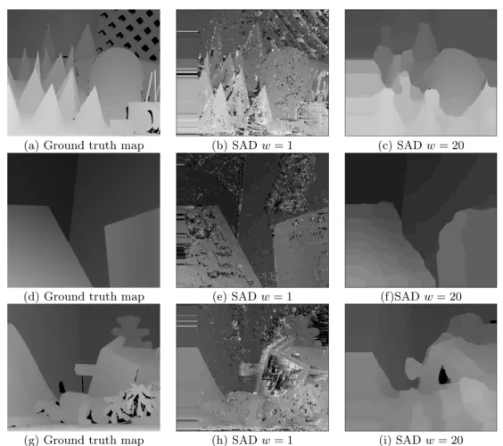
(a) Ground truth map (b) SAD w = 1 (c) SAD w = 20
(d) Ground truth map (e) SAD w = 1 (f)SAD w = 20
(g) Ground truth map (h) SAD w = 1 (i) SAD w = 20
Fig. 1: Disparity maps generated for different test synthetic stereo pairs by applying the SAD algorithm
3 Correlation using fixed size windows
The main disadvantage regarding to the algorithms de-scribed in section 2.1 is that these can not be imple-mented in a dedicated hardware for real-time process-ing. However, in this research we are interested on stereo matching algorithms suitable for real-time image pro-cessing. The most adapted are correlation-based algo-rithms such as the sum of absolute differences (SAD), because they have a regular structure with fixed run-time. In addition, several systems that use correlation-based algorithms have been described in the literature.
In majority of area-based algorithms, a rectangular vicinity centered on a reference pixel in one of the im-ages from a stereo pair is compared with similar vicini-ties for some pixels in the same raster line of the other image. Vicinities are called correlation windows and can be compared using a correlation-based measure such as SAD: Cl(x, y, s) = i=wx X i=−wx j=wy X j=−wy |Il(x + i, y + j)− Ir(x + s + i, y + j)| ,
where Il(x + i, y + j) and Ir(x + i + s, y + j) are the
grey scale values of the pixels within the window in both images, called the left and right images respectively. (2 × w + 1)2 is the correlation window size, s is the shift
of the window in the right image and the maximal shift of the correlation window in the right image is sm. A
correlation coefficient is determined for each pixel and the shift that minimizes the correlation coefficient is re-tained as the disparity. These algorithms yield a dense depth map, but they need a high runtime.
Disparity maps generated by applying the SAD al-gorithm on different synthetic stereo pairs are shown in Fig. 1. The main problem with this algorithm is to se-lect the correlation window size. High window size values allow to determine the correct correlation values in areas with uniform texture. However, these window sizes imply a high computational demand and erroneous values at certain points due to the blurring edges and that small features are eliminated Fig. 1.(c),(f),(i). On the other hand, small window sizes imply low computational de-mand but the correlation coefficient measurement is sen-sitive to noise, hence, erroneous values at uniform texture regions are generated as seen in Fig.1.(b),(e),(h).
In order to avoid of the main disadvantages of the SAD algorithm (blurring edges and noise in homoge-neous areas), the use of an adaptive correlation window based on a similarity criterion suitable for real-time im-age processing is proposed. Hence, in this article, an area-based stereo matching algorithm in which the size and shape of the correlation window are adjusted by each pixel in the reference image according to its content and his FPGA implementation are described. The proposed algorithm uses the grey scale values variations in the win-dow as a technique to determine the similarity criterion. It is demonstrated that even with a simple similarity cri-terion, the proposed algorithm outperforms other adap-tive window algorithms and enables to be implemented in a dedicated hardware for real-time processing such as FPGA devices. Furthermore, it is demonstrated that the developed FPGA architecture outperforms to the most of other real-time area-based stereo matching algorithms reported in the literature and allows to maintain a high processing speed.
The rest of this paper is organized as follows: sec-tion 4 presents the proposed algorithm and the tech-nique to determine the similarity criterion used for the selection of pixels. In section5, the FPGA architecture for the proposed algorithm is described. Experimental results for differents synthetic stereo pairs, a comparison with other adaptive window algorithms, a comparison re-garding to several real-time stereo matching tions reported in the literature and FPGA implementa-tion results are detailed in secimplementa-tion6. Finally, section7
concludes this article.
4 The proposed method
The main objective in this research is to develop one algorithm that uses a single window, which is processed only once using a recursive approach appropriate for ded-icated hardware real-time proccesing implementation. In order to explain the proposed algorithm, the Tsukuba scene shown in the Fig.2.(a) is used. This image presents multiple objets at differents depths. Depth of each ob-ject is indicated using grey scale values as shown in the Fig.2.(b).
a) Original image b) Ground truth
Fig. 2: Tsukuba scene
The pixels within the small overlapped window as il-lustrated in Fig. 3.(a) include projections of points of different objects as shown at Fig. 3.(b). When correla-tion coefficient is computed using all the pixels of this window, the averaging effect yields errors on the esti-mated disparity. On the other hand, Fig.3.(c) shows a vicinity in which only the pixels that are the projections of points of the same object are used while the other are not considered and eliminated of the window. Pixels that are not considered are indicated in black. Color of the pixels retained is similar to the central pixel and they have the same depth as shown in the Fig.3.(d). By using this window, disparity estimation is more accurate.
a) Fixed window b) Disparities
c) Adaptive window d) Disparities
Fig. 3: Fixed versus adaptive window
In the Similarity-Based Adaptive Window algorithm (SBAW), a fixed size window is centered on each pixel of the reference image, but only the selected pixels by sim-ilarity criterion are used to compute the correlation co-efficient. Any correlation coefficient based on gray scale values can be modified using this technique. For exam-ple, the standard SAD expression turns into:
Cl(x, y, s) = i=wx X i=−wx j=wy X j=−wy β(x, y, i, j) × (1) |Il(x + i, y + j) − Ir(x + s + i, y + j)| ,
where the coefficient β(x, y, i, j) is equal to 1 when the pixels from the correlation window are projections of the selected point, otherwise is zero. i and j are used in the sum process. This corresponds to define a window with variable size and shape that can be adapted to the lo-cal reference image data. In order that pixels within the window correspond to the same object than the selected pixel Pl(x, y), a pixel Pl(x + i, y + j) is included or
ex-cluded from the window according to a similarity crite-rion. If the two pixels are similar, β(x, y, i, j) is set to 1, otherwise is zero.
4.1 Techniques to define the similarity criteria
Several techniques are able to be used to define the simi-larity criterion. However, a technique based on recursive approach is more suitable in terms of computational ef-ficiency and facilitates his hardware implementation. In this section a technique based on the comparison of the grey scale values is described. It is demonstrated that even a simple technique allows the use of adaptive win-dows achieving to increase the disparity map accuracy. 4.1.1 Criterion based on comparison of the grey scale values
We can assume that two pixels are not similar and they have different disparity, when there is a significant dif-ference between their grey scale values [40]. Then, we set β(x, y, i, j) to 1 only when the grey scale value p(x + i, y + j) is close to the grey scale value of the selected pixel p(x, y), i. e., if:
|p(x + i, y + j) − p(x, y)| ≤ T (x, y) , (2)
where T (x, y) is the maximum acceptable difference be-tween the grey scale values. In practice, it is sufficient to assign the value of T ∀ p(x, y) as a constant value de-fined by the user. However, the problem is to determine an appropriate value for all points contained in the in-put stereo pair. By analyzing simulations performed in Matlab R2013a, it was determined that small values of T are most appropriate for points contained in regions near the edges while higher values of T are more suit-able for regions which belong to the same object. On the other hand, it was determined that by assigning a con-stant value to T erroneous stimations occur in regions where due to the color of selected pixel, some pixels of to the same object are eliminated from the correlation window. Therefore, assigning to T a constant value does not ensure that an appropriate value for each point of the input stereo pair is used, furthermore, wrong stimations will be obtained at some points.
In order to compute T the use of the sum of absolute differences between the selected pixel and vicinity pixels is proposed. This value of T is adapted appropriately to most points contained in the stereo pair. i.e., in homo-geneous areas in which it is supposed that all the points correspond to the same object, T is small and allows to avoid noise points and punctual features of the object. This enables to increase the accuracy of the correlation measure. On the other hand, when multiple objects are projected, the T value increases, however, this value al-lows to differentiate between the object that includes the selected point and others. Through multiple tests per-formed in Matlab it was determined that the minimum pixels required for an T accurate estimation are the pix-els around the selected pixel, Il(x, y) (cf. Fig. 4,
equa-tion4).
Finally, it was determined that in areas where the variation of the correlation window is high, mainly the points close to the corners of objects, T value is high and the disparity estimation accuracy decreases. Even with this limitation a high accuracy could be reached (cf. Fig.4). In this case j = 1 and T could be defined as T = K, equation4.
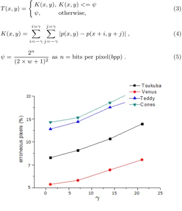
However, using a simple adequation it is possible to increase the accuracy level. Considering that when the selected point is a corner, T value is high and points of diferent objects would be include in the correlation win-dow. Therefore, when T value is high, this value could be replaced with a smaller value that allows to differentiate between the object that includes the selected point and the others. Based on the assumption that into a large correlation window, multiple objects are projected, i.e., multiple corners are included. If the correlation window size increases, the number of projected objects and cor-ners proportionally increases. We propose compute the T value adding a restriction parameter applicable on the corner points, equation3. This parameter is computed as shown in equation5and enables to reduce the errors at corners and increase the general accuracy near to 2%. Fig.5shows some correlation windows for the Tsukuba scene using Equation 3. Although several techniques can be used to define the similarity criterion. We can affirm that even using a simple technique like the pro-posed in this article, any rectangular correlation window can be adapted to the local variations in the stereo pair.
T (x, y) = ( K(x, y), K(x, y) <= ψ ψ, otherwise, (3) K(x, y) = i=γ X i=−γ j=γ X j=−γ |p(x, y) − p(x + i, y + j)| , (4) ψ = 2 n
(2 × w + 1)2 as n = bits per pixel(bpp) . (5)
Fig. 5: The selected pixels using the proposed algorithm
In standard algorithms, the disparity dl(x, y) is
de-fined as the shift s giving the maximum (or minimum) value of the correlation values, equation 1. In order to detect occlusions, the left-right consistency is used. For each pixel, if the disparity dl(x, y) computed using
the left image as a reference is equal to the disparity dr(x + Sm, y) computed using the right image as the
reference, equation6, the solution is considered as cor-rect. Otherwise the pixels are marked as occluded and the disparity can be computed with subpixel accuracy or be assigned as the minimum value between dl(x, y)
and dr(x + Sm, y). In this case the minimum value
be-tween dl(x, y) and dr(x + Sm, y) will be used.
Cr(x, y, s) = i=wx X i=−wx j=wy X j=−wy β(x, y, i, j) × (6) |Ir(x + i, y + j) − Il(x − s + i, y + j)| , 4.2 Computational complexity
In order to explain the computational complexity of the proposed algorithm, first, the SAD computational plexity is analyzed. In this case the computational com-plexity is defined as following: OSAD(M S D/d0); where
M is the size of the input image. S is the size of the cor-relation window. D is the maximum expected disparity and d0is the increment regarding to the disparity values. Like SAD, the proposed algorithm possesses a computa-tional complexity defined in the same terms, Table 2. i.e. OSAD = OSBAW= O(M S D/d0). Based on the high
efficient of to the SAD algorithm and considering that his computational complexity is equal to the complex-ity of the proposed algorithm. It is possible to afirm the high efficient of the proposed method. In addition, when SAD applying left-right consistency was implemented, the SAD runtime was similar to the proposed method runtime for the same setup, Table 1. As can be seen, the increment on the runtime, in all the cases near to 30%, is the time required for the T value computation.
Table 1: Runtime for the proposed method
Scene/Algorithm Window size (2 ∗ w + 1) 9 25 49 81 121 169 Tsukuba/SBAW 22.4 27.7 35.1 42.7 50.4 57.1 Venus/SBAW 31.3 38.9 50.6 66.1 83.4 114 Teddy/SBAW 46.3 66.4 98.7 138 191 252 Cones/SBAW 46.3 66.4 98.7 138 191 252 Tsukuba/SAD 15.3 17.6 20.9 25.3 30.8 40.6 Venus/SAD 22.7 27.1 33.6 41.4 58.5 79.6 Teddy/SAD 39.5 55.2 79.0 117 155 162 Cones/SAD 39.5 55.2 79.0 117 155 162 *All the runtimes are measured in seconds and were obtained
via MatLab
Table 2: Pseudo code for the Similarity-Based Adaptive Window algorithm (SBAW)
Parameter definition
H: The size of an image I (H = Xresolution× Yresolution)
W : The size of a correlation window (W = (2 × w + 1)2) S: The maximum expected disparity (S = Sm)
s0: Increase of disparity (s0= 1)
Algorithm: Similarity-Based Adaptive Window Complexity: O(H W S/s0)
1: Compute the ψ value (equation5) Left image as reference
For all pixels p(x, y) which satisfy x >= w, y >= w and x <= Xresolution− w − S, y <= Yresolution− w
2: Compute the K(x, y) value (equation4) 3: Compute the T (x, y) value (equation3) For s = 1 with increments equal to s0up to S
4: Compute the Cl(x, y, s) value (equation1)
End
5: (dl(x, y) = arg minsCl(x, y, s))
End
Right image as reference
For all pixels p(x, y) which satisfy x >= w + S, y >= w and x <= Xresolution− w, y <= Yresolution− w
6: Compute the K(x, y) value (equation4) 7: Compute the T (x, y) value (equation3) For s = 1 with increments equal to s0up to S
8: Compute the Cr(x, y, s) value (equation6)
End
9: (dr(x, y) = arg minsCr(x, y, s))
End
Compute the disparity map
For all pixels p(x, y) which satisfy x >= 1, y >= 1 and x <= Xresolution− W − S, y <= Yresolution− W
10: (d(x, y) = min(dl(x, y), dr(x + Sm, y))
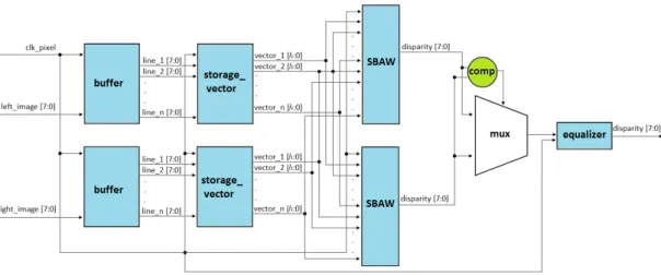
Fig. 6: General diagram of the developed FPGA architecture
5 The FPGA architecture
Although the algorithm presented in section4possess a low mathematical complexity, compute a disparity map for a 384×288 pixel resolution synthetic stereo pair (pixel resolution of the Tsukuba scene), implies a runtime close to 1 second. This time is not appropriate for real-time applications. This was the main motivation to search ef-ficient ways to implement the proposed algorithm, an FPGA implementation was selected. In Fig.6, an overview of the developed FPGA architecture is shown. This archi-tecture have three inputs, clk pixel as the pixel rate of the input stereo pairs, left image [7:0] and right ima ge [7:0] as gray scale values of pixels from the left and right images respectively and one output, disparity [7:0], corresponding to disparity value for the selected pixels. The developed FPGA architecture allows to pro-cess input stereo pairs of x × y pixel resolution, where x ∀ N and y <= 2048. Furthermore, this architecture enables to compute the disparity maps by applying the SBAW algorithm using n × n correlation windows, where n = 2k + 1 ∀ k ∈ N, and considering a maximum ex-pected disparity equal to 2k− 1 ∀ k ∈ N. Its general behavior can be described as following: first, the buffer modules store gray scale values of pixels contained in n horizontal lines for both left and right images of input stereo pair. After, the storage vector modules gener-ate n storage vectors, each vector consists of a regis-ter defined by the gray scale values for n vertical pixels stored in one of the horizontal lines stored above. Then, left-disparity and right-disparity values are computed via SBAW modules separately. Later, a multiplexer (mux) sets the final disparity value as the minimum of two dis-parity values previously computed by the SBAW mod-ules. Finally, the equalizer module convert the final dis-parity value to gray scale values of 8 bits of depth. In the following subsections the architecture of all the individ-ual modules is shown in detail.
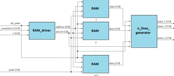
5.1 The buffer module
In order to store necessary data for the disparity com-putation, the use of buffer modules is proposed. These modules allows to store the gray scale values correspond-ing to the pixels contained in n horizontal lines from an image and enables to read all stored lines in parallel. An overview of the FPGA architecture of the buffer module is shown in Fig.7. This module consists of three differ-ent sub-modules, The RAM driver module manages an array of n + 1 single-port ram units (RAM) assigning to each one the corresponding address, address [9:0], and the corresponding write-read value, w/r [n+1:0]. The w/r [n+1:0] output consist of one logic vector of n + 1 bits of size, the write-read value of each of the RAMs is determined by each one of the bits of the w/r [n+1:0] output. The outputs of the buffer mod-ules are determined via state machines, which are con-trolled by horizontal resolution of the input stereo pairs, x resolution [11:0], and the correlation window size n [5:0]. In Table3, the behavior of the state machine for the output w/r [n+1:0] is shown, the number of states is set as n + 1. n RAMs are in read mode while one RAM is in write mode for all the states at any time. On the other hand, in Table4the behavior of the state machine for output address [9:0] is shown.
Table 3: Behavior of the state machine for the w/r [n+1:0] output of the buffer module
State Behavior
1 If address < x resolution [11:0] and state = 1 then w/r [n+1:0] = · · ·00001 else state = 2 2 If address < x resolution [11:0] and state = 2
then w/r [n+1:0] = · · ·00010 else state = 3 . . . . . .
n+1 If address < x resolution [11:0] and state = n+1 then w/r [n+1:0] = 1000· · · else state = 1
Fig. 7: FPGA architecture for the buffer module
Table 4: Behavior of the state machine for the address [9:0] output of the buffer module
State Behavior
1
If address < x resolution [11:0] and state = 1 then address [9:0] = address +1 else state = 2 ,
address = 0 2
If address < x resolution [11:0] and state = 2 then address [9:0] = address +1 else state = 3 ,
address = 0 . . . . . . n+1
If address < x resolution [11:0] and state = n+1 then address [9:0] = address +1 else state
= 1 , address = 0
The RAM module consists of a synchronous single-port ram unit, its general settings was set as: type = synchronous, width = 8, depth = 2048, operation type = single port, all the others parameters are defined as default. These parameters allow to store the gray scale values for each pixel contained in horizontal lines from images of up to 2048 horizontal resolution with 8 bits of color depth. The use of an RAM modules array enables to read the gray scale values of the pixels contained in n horizontal lines from an image, see Table5
Table 5: Behavior of the array of RAM modules
w/r [n+1:0] Read lines by RAM1,2,3,4,n
1000· · · -,-,-,-0100· · · 1,-,-,-0010· · · 1,-,-,-0001· · · 1,2,3,-· 1,2,3,-· 1,2,3,-·0001 1,2,3,n 1000· · · n+1,2,3,n 0100· · · n+1,n+2,3,n 0010· · · n+1,n+2,n+3,n 0001· · · n+1,n+2,n+3,n+4 · · ·0001 n+5,n+2,n+3,n+4
The n lines generator module reads the outputs from the RAM modules and determines which RAMs modules are in read mode at any time. In order to assign lines in the outputs of the n lines generator module in ascending form, i.e., pixel 1 [7:0] = input image line number l, pixel 2 [7:0] = input image line number l+1, pixel n [7:0] = input image line number l+n-1, the outputs from the RAM modules in read mode are assigned to the outputs of the n lines generator mod-ule as seen in Table 6, the first column corresponds to the output w/r [n+1:0] of the RAM driver module, the second column corresponds to the numbers of the RAM modules assigned to the outputs of the n lines generator module.
Table 6: Output assignment for the n lines generator module
w/r [n+1:0] pixel l [7:0] for l=1,2,...,nAssignment 1000· · · 2,3,4,5,· · ·,n 0100· · · 3,4,5,· · ·,n,1 0010· · · 4,5,· · ·,n,1,2 0001· · · 5,n,· · ·,1,2,3 · · ·0001 1,2,3,4,· · ·,n-1
5.2 The storage vector module
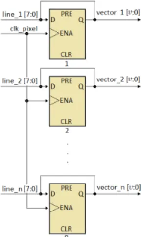
To compute the disparity value via the SBAW algorithm, it is necessary to have stored the gray scale values of all the pixels from the correlation window. However, the buffer module only provides the gray scale values of one of the vertical lines of the correlation window at each time. In order to store the rest of the values efficiently, use of n register-based storage vectors is proposed. All
storage vectors possess a similar behavior with respect to a shift register unit, however, these allow to read multiple data in one clock cycle. In general, when a line begins, the gray scale value of the pixel with coordinate (1) is stored in index [7:0] of one storage vector, in the follow-ing clock cycle, this value is moved to index [15:8] and the gray scale value of the pixel with coordinate (2) is stored in index [7:0]. A similar process is repeated for all the pixels that integrate the line. In Fig.8, behavior of storage vector module with settings as follows: num-ber of lines to process = n, v = 8 × n − 1 is shown. In Fig. 9 the architecture of the storage vector module is shown.
Fig. 8: Behavior of the storage vector module
Fig. 9: FPGA architecture for the storage vector module
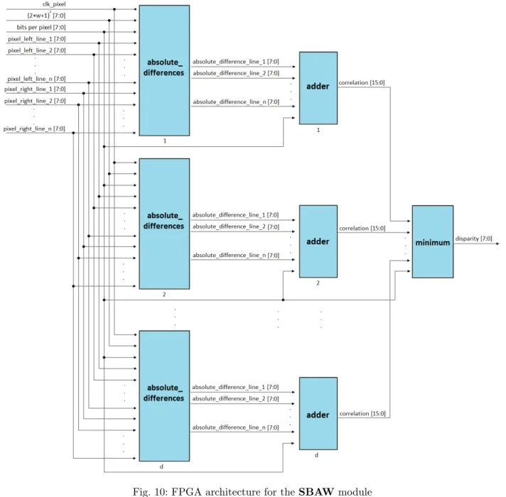
5.3 The SBAW module
For the computation of the disparity map via the SBAW algorithm, a pixel-parallel and window parallel architec-ture was designed; the necessary data are obtained from the storage vector modules, using the appropriate in-dexes is possible to process video streams at real-time, giving as result disparity maps of (X − w) × (Y − w) pixel resolution, where X, Y corresponds to the values of resolution of the input video stream and (2 × w + 1)2 is the size of the correlation window used.
The architecture of the SBAW module is presented in Fig.9, its general behavior is described as following: first, the absolute differences modules compute the absolute difference between pixels from left and right images of the correlation window. This process is ex-ecuted in each of the dmax+ 1 absolute differences
modules, implemented in parallel, which are configured for expected disparity levels from 0 until dmax, where
each module process only one disparity level and com-putes the absolute differences only for pixels which are projections of selected pixel, i. e., all pixels belong to the same object, equations 3 - 5. Then, the output of each of the absolute differences modules are sent to its corresponding adder module, in this step adder blocks compute the sum of the absolute differences for all pix-els retained in the correlation window. Finally, the min-imum module assigns the corresponding index for all correlation values, then, determines the minimum corre-lation value and set the disparity value as the index of the minimum correlation value. In the developed FPGA architecture, two SBAW modules were implemented in parallel form where the first module uses the left image as reference and the second module uses the right image. 5.3.1 The minimun module
In order to reach an appropriate propagation of the cessed data, the use of the minimum module is pro-posed. It consists of an index generator module and k min modules implemented in sequential form. Firstly, the index generator module assigns the corresponding indexes to all the correlation values from the previous stage, then, the min1 module, receives all the
corre-lation values and their indexes. Afterwards, this mod-ule determines the minimum values for correlation val-ues, which are sorted by pairs with unrepeated correla-tion values for any pair; the minimum correlacorrela-tion values and their indexes obtained here are placed in the vec-tors (value [x:0], where x = 16 × (dmax+ 1) − 1, and
index [x:0], where x = 8×(dmax+1)−1), respectively.
This process is repeated in sequential form until only one correlation value and its index are placed in the output vectors.
5.4 The equalizer module
In order that disparity values are appropriate for display-ing in LCD screens or another output devices, the use of the equalizer module is proposed. This module con-vert the final disparity value to gray scale values through disparity [7:0]×256/dmax. To reduce the hardware
resource consumption, this process was performed with a CASE structure, which considers all expected dispar-ity levels and turns the final dispardispar-ity value into integer constant value corresponding to the previously described operation.
Fig. 10: FPGA architecture for the SBAW module
(a) Tsukuba scene (b) Venus scene
(c) Teddy scene (d) Cones scene
Fig. 12: Behavior of the developed FPGA architecture
6 Discussion and analysis of results
The FPGA architecture presented in section 5was im-plemented with a top-down approach. All the modules were programmed using Verilog, Quartus II Web Edition version 10.1SP1 was used for the synthesis process. In or-der to verify functionality of all the modules individually, post-synthesis simulation in ModelSim-Altera 6.6c were executed.
6.1 Simulation results
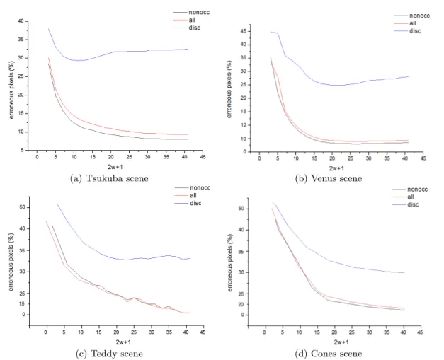
In order to evaluate the behavior of proposed algorithm, the developed FPGA architecture was simulated in Model Sim-Altera 6.6c using different synthetic stereo pairs and different sizes for correlation windows. The selected tests stereo pairs were the Tsukuba, Venus, Teddy and Cones scenes. The window sizes used were: {3, 5, 7, 9, 11, 13, 15, 17, 19, 21, 23, 25, 27, 29, 31, 33, 35, 37, 39, 41}. In Fig. 12
the behavior of the error obtained in the disparity maps generated for different window sizes for the selected syn-thetic stereo pairs are shown, this demonstrates the
effec-tiveness of the developed FPGA architecture. Disparity maps have been compared using the method proposed in [32], in which the percentage of pixels with a disparity error greater than one is computed. Three percentages are computed, one for all non-occluded pixels (nonocc), one for all pixels (all) and one for occluded pixels near depth discontinuities (disc). Performance for occluded pixels are not considered because no one algorithm com-pute occluded pixels explicitly.
On the other hand, Fig. 13 presents the error per-centage of all pixels (all) for all evaluated synthetic stereo pairs obtained via SBAW algorithm compared with using the SAD algorithm. For the SBAW algorithm, if a small correlation window is used, error is more important than error for the SAD algorithm because some pixels of the window are not used and effective area of the used window is reduced. However, error in untextured areas is significantly reduced when a large correlation window is used. Error at discontinuities grows with the correlation window but it is smaller than the error for the SAD algo-rithm. So, we can affirm that performance of the SBAW algorithm is better when a large correlation window is used.
(a) Tsukuba and Venus scenes
(b) Teddy and Cones scene
Fig. 13: Comparison between the SBAW algorithm and the SAD algorithm for all the erroneous pixels (all)
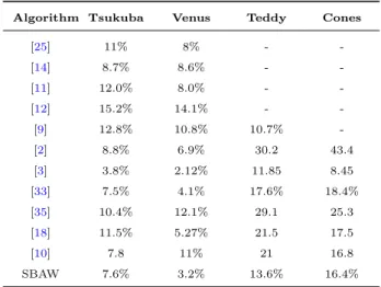
In Table7quantitative results of the number of erro-neous pixels obtained by the proposed algorithm for the Tsukuba, Venus, Teddy and Cones scenes, using a 41×41 correlation window compared with other real-time stereo matching algorithms, reported in the literature, are pre-sented. In order to process and collect the data presented in Table 7, the developed architecture was scaled and synthesized to operate with the appropriate maximum expected disparity values. For all cases, Quartus II Web Edition version 10.1SP1 was used for the synthesis pro-cess and simulations in ModelSim-Altera 6.6c were ex-ecuted. By analyzing Table 7, it is observed that the results of the algorithm present a improvement regard-ing to the most of real-time-stereo matchregard-ing algorithms reported in literature. In addition, similar to the major-ity of these algorithms, the proposed algorithm presents a high performance with small values of maximum dis-parity (Tsukuba, Venus scenes); whilst, a medium per-formance with high values of maximum disparity (Teddy, Cones scenes) is observed. The generated disparity maps for the Tsukuba, Venus, Teddy and Cones scenes consid-ering 2 × w + 1 = 41 are shown in Fig. 14.
Table 7: Comparison between quantitative results of real-time-stereo matching algorithms
Algorithm Tsukuba Venus Teddy Cones
[25] 11% 8% - -[14] 8.7% 8.6% - -[11] 12.0% 8.0% - -[12] 15.2% 14.1% - -[9] 12.8% 10.8% 10.7% -[2] 8.8% 6.9% 30.2 43.4 [3] 3.8% 2.12% 11.85 8.45 [33] 7.5% 4.1% 17.6% 18.4% [35] 10.4% 12.1% 29.1 25.3 [18] 11.5% 5.27% 21.5 17.5 [10] 7.8 11% 21 16.8 SBAW 7.6% 3.2% 13.6% 16.4%
Furthermore, comparisons with respect to other adap-tive window algorithms, such as the SMW algorithm [1], the Census algorithm [39] and the Hirschm¨uller (HIR) al-gorithm [15], were performed. In order to perform com-parisons, the synthetic image shown in Fig. 15 (a) is used. Two textured objects are present in the synthetic scene, which appear as a square and as the background in the image. Fig. 15(b) shows the ground truth map, where well defined edges correspond to depth disconti-nuities.
(a) Left image (b) Ground truth map
Fig. 15: Test scene stereo pair
Fig.16shows the disparity maps computed by all the evaluated algorithms using a 27 × 27 correlation window.
(a) SMW algorithm (b) HIR algorithm
(c) Census algorithm (d) SBAW algorithm
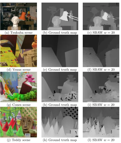
(a) Tsukuba scene (b) Ground truth map (c) SBAW w = 20
(d) Venus scene (e) Ground truth map (f) SBAW w = 20
(g) Cones scene (h) Ground truth map (i) SBAW w = 20
(j) Teddy scene (k) Ground truth map (l) SBAW w = 20
Fig. 14: Disparity maps generated for different test synthetic stereo pairs
In the areas corresponding to a single object, all the algorithms estimate the disparity precisely, because the correlation window is large, however, the averaging effect generates errors at depth discontinuities, which is clearly visible in the disparity maps of the SMW and HIR algo-rithms (Fig.16(a) and (b)). The HIR algorithm reduces errors at discontinuities, but there are still false match-ings due to the central window, which is always used. Square windows used in the SMW algorithm are well adapted for this image. However, there are false match-ings at the corners of the central square object. The per-formance of the Census algorithm is worse because of the repetitive pattern in the image. With the SBAW algo-rithm (Fig.16(d)), the estimated disparity map is very similiar to the ground truth, even near of both depth discontinuities and at the corners of the central square object. Table10shows the numerical values obtained by perform this comparison. All values shown in this table were obtained by Matlab implementations for the HIR, SMW and Census algorithms. The erroneous pixels were measured by applying the equation 7; where I1 is the
ground truth map. I2is the generated disparity map by
a particular algorithm. x is the horizontal resolution of the input image. y is the vertical resolution of the input image and N is set as x × y. In all the cases a similar setup was applied and similar behavior for different test escenes was observed.
σ = 2 v u u u t 1 N i=x,j=y X i=1,j=1 (I1(i, j) − I2(i, j))2 (7)
Table 10: Errors for the synthetic pair (in %)
Non-occluded Near discontinuities Algorithm Window size Window size
15X15 21X21 27X27 15X15 21X21 27X27 HIR [15] 2.24 3.51 5.01 27.32 33.05 35.63 SMW [1] 0.53 0.86 1.4 8.9 12.38 16.49 Census [39] 3.21 3.16 3.62 26.97 29.97 33.46 SBAW 0.34 0.34 0.33 4.94 4.53 4.37
Table 8: Logic elements (combinational functions and logic registers) consumption for different configurations of the developed FPGA architecture
aa 2w + 1 dmax 3 9 15 21 27 33 41 15 7,375 47,286 119,991 143,988 165,586 182,144 191,252 31 14,699 94,099 238,782 286,536 329,516 362,466 380,591 63 29,104 186,316 470,400 561,610 645,851 710,434 726,757
Table 9: Memory bits consumption for different configurations of the developed FPGA architecture
aa 2w + 1 dmax 3 9 15 21 27 33 41 5 65,636 163,840 262,144 344,064 442,368 573,440 671,744 31 65,636 163,840 262,144 344,064 442,368 573,440 671,744 63 65,636 163,840 262,144 344,064 442,368 573,440 671,744
In Table10only two percentages are computed, one for all the pixels and one for the pixels near discontinu-ities, because objects are well textured. The quantitative comparison demonstrate that the error percentages in-crease with window size for SMW and HIR algorithms, but decrease with window size for the SBAW algorithm. In the SMW algorithm, the window is adapted accord-ing to the local texture as confirmed by the low error percentages, but a large window is not well adapted at the corners and the error percentages rise up with the size window. Percentage errors in the Census algorithm are high due to the repetitive patterns in the image, but their performance in discontinuities is better than the HIR algorithm. Applying SBAW algorithm using a small window, errors are caused by a lack of information in the correlation window. On the other hand, with large win-dows, the errors near to depth discontinuities are avoided with the SBAW algorithm. This behavior is confirmed by low error percentages of the SBAW algorithm for pixels near to depth discontinuities. For the SBAW algorithm, the best performance is obtained with a large window. This is a difference and an advantage with respect to the others algorithms where the window size must remain small.
Tables8-9 present a comparison of the use of hard-ware resource regarding to all the synthesized and sim-ulated configurations of the developed FPGA architec-ture. By analyzing Fig. 12, the acceptable behavior for the SBAW algorithm can be determined by using a 21×21 correlation window, in this case the hardware consump-tion for the developed FPGA architecture is appropriate for the majority of the medium gamma of FPGA devices such as the Stratix III family of Altera or Spartan III family of Xilinx, however, for higher window sizes only high gamma FPGA devices such as the Stratix V family
of Altera support the hardware resource consumption. It is the user decision to select the configuration of the SBAW algorithm more appropriate to his particular re-quirements.
Finally, Table 11 presents comparisons of process-ing speed regardprocess-ing to other real-time stereo matchprocess-ing algorithms reported in the literature. Due to the mathe-matical simplicity of the proposed algorithm, the devel-oped architecture does not require complex arithmetical operations such as calculation of quotients and radicals (which require a high runtime), hence, it maintains a high processing speed. When comparison of processing speed is conducted, Table11, it is observed an increase with respect to other algorithms implemented in FPGA devices of up to 93,061,120 pixels per second.
Table 11: Processing speed for differents real-time stereo matching algorithms
Algorithm Resolution Frames/s Pixeles/s [11] 1280×1024 65 85,196,800 [33] 640×480 68 20,889,600 [3] 256×256 100 6,553,600 [35] 1280×1024 50 65,536,000 [10] 384×288 1250 138,240,000 [18] 640×480 230 70,656,000 [26] 320×240 574 44,083,200 [9] 1024×1024 102 106,954,752 SBAW* 450×375 592 99,900,000 SBAW* 434×383 601 99,899,422 SBAW* 384×288 904 99,975,168 *Operating frequency = 50 MHz
6.2 Implementation results
The developed FPGA architecture was implemented in a FPGA Cyclone II EP2C35F672C6 embedded in the development board DE2 of Altera and the selected con-figuration for the SBAW algorithm was dmax = 15, 2 ×
w + 1 = 15. In order to acquire input stereo pairs, a TRDB DC2 board connected in the first port of expan-sion of the DE2 board is used. TRDB DC2 board pro-vides stereo pairs of 1280×1024 pixel resolution in RGB scale. In order to determine the gray scale value of the input stereo pairs, the value of the green channel was used as a gray scale value. With the purpose of reaching appropriate values to the environmental characteristics of the input scene, the implementation enables to con-figure the exposition of the cameras. For assigning the exposure value of the cameras, 4 push buttons of the DE2 board are used. The function of each of these push buttons is detailed in the Table12.
Table 12: Control of the board TRDB DC2
Name Description Key0 Reset the frame capture Key1 Assign the exposure value Key2 Pause the frame capture Key3 Continuous frame capture
Output disparity maps was displayed in a terasIC 4,3” LCD screen of 800×480 pixel resolution connected to the second expansion port of the DE2 board. The processing speed of the FPGA implementation is equal to 76 fps (99,614,720 pixels/s) for the input stereo pairs of 1280×1024 pixel resolution. The resource consumption of the implemented architecture is shown in Table13.
Table 13: Hardware resource consumption for the FPGA implementation
Resource Demand
Total logic elements 27,061/33,216 (81%) Total combinational functions 21,639/33,216 (65%) Dedicated logic registers 15,180/33,216 (46%) Total pins 161/475 (34%) Total Memory Bits 407,472/483,840 (84%) Embedded multiplier elements 0/70 (0%) Total PLLs 2/4 (50%)
7 Conclusions
In this article, an area-based algorithm suitable for real-time stereo matching using an adaptive window tech-nique based on a grayscale similarity criterion was pre-sented. Only selected pixels are used in the window ac-cording to their similarity to the central pixel. Further-more, a technique to determine similarity criterion has been described and it was demonstrated that even using a simple similarity criterion, the SBAW algorithm out-performs other adaptive window algorithms reported in the literature. The best performance of the SBAW al-gorithm was obtained with a large window appropriated for homogeneous areas. However, since the effective size and shape of the window were adaptive, blurring effects at discontinuities are avoided.
In order to improve its processing speed, the proposed algorithm was implemented in a FPGA device. The de-veloped FPGA architecture outperforms other real-time stereo matching algorithms in the literature, allowing high accuracy level and enables both increasing the pro-cessing speed and to be implemented in the majority of the medium gamma FPGA devices.
Furthermore, an important characteristic of the pre-sented architecture is the scalability permissible; all the modules and submodules which integrate the developed FPGA architecture, easily allow to be adapted for pro-cessing of larger correlation windows than the simulated and implemented correlation windows. On the other hand, the FPGA architecture enables to configure different lev-els of maximum expected disparity (dmax), consequently,
it is possible to configure the module for the computation of disparity maps with appropriate values to the environ-mental characteristics of the input video streams. This allows that the developed architecture can be applied to a wide range of applications of real-time stereo vision such as positioning systems for mobile robots and recog-nition, detection and tri-dimensional reconstruction of objects.
References
1. A Fusiello VR, Trucco E (2000) Symmetric stereo with multiple windowing. International Journal of Pattern Recognition and Ar-tificial Inteligence 8(14):1053–1066
2. Aguilar-Gonz´alez A, P´erez-Patricio M, Arias-Estrada M, Camas-Anzueto JL, Hern´andez-deLe´on HR, S´anchez-Alegr´ıa A (2015) An fpga correlation-edge distance approach for disparity map. In: Pro-ceedings of IEEE International Conference on Electronics, Com-munications and Computers (CONIELECOMP 2015), Chulula, M´exico 21–28
3. Alba A, Arce-Santana E, Aguilar-Ponce RM, Campos-Delgado DU (2014) Phase-correlation guided area matching for realtime vision and video encoding. J Real-Time Image Proc 9:621–633
4. Asadi E, Bottasso CL (2013) Delayed fusion for real-time vision-aided inertial navigation. J Real-Time Image Proc DOI:10.1007/s11554-013-0376-8
5. Bartczak B, Koeser K, Woelk F, Koch R (2007) Extraction of 3d freeform surfaces as visual landmarks for real-time tracking. J Real-Time Image Proc 2:81–101
6. Darabiha A, MacLean W, Rose J (2006) Reconfigurable hardware implementation of a phase-correlation stereo algorithm. Journal of Machine Vision and Applications 17:116–132
7. Diaz J, Ros E, Pelayo F, Ortigosa E, Mota S (2006) Fpga based real-time opticalflow system. IEEE Transactions on Circuits and Systems for Video Technology 16:274–279
8. FeiyangCheng, HongZhang, DingYuan, MinguiSun (2013) Stereo matching by usingthe global edge constraint. Neurocomputing 131(11):217–226
9. Georgoulas C, Andreadis I (2010) Fpga based disparity map com-putation with vergence control. Microprocessors and Microsystems 34:259–273
10. Georgoulas C, Andreadis I (2011) A real-time fuzzy hardware structure for disparity map computation. J Real-Time Image Proc 6:257–273
11. Georgoulas C, Kotoulas L, Sirakoulis GC, Andreadis I, Gasteratos A (2008) Real-time disparity map computation module. Micropro-cessors and Microsystems 32:159–170
12. Gong M, Yang YH (2005) Near real-time reliable stereo matching using programmable graphics hardware. Computer Vision and Pat-tern Recognition, IEEE Computer Society Conference on 1:924– 931
13. Granados S, Barranco F, Mota S, D´ıaz J, Ros E (2014) On-chip semidense representation map for dense visual features driven by attention processes. J Real-Time Image Proc 9:171–185
14. Guerra-Filho G (2012) An optimal timespace algorithm for dense stereo matching. J Real-Time Image Proc 7:69–86
15. Hirschmuller H (2001) Improvements in real-time correlation-based stereo vision. In: Proceedings of IEEE workshop on Stereo and Multi-Baseline Vision, Kauai, Hawaii, 141–148
16. ISAKOVA N, cuk BASAK S, SONMEZ A (2010) Fpga design and implementation of a real-time stereo vision system. Circuits and Systems for Video Technology, IEEE Transactions on 20:1–5 17. Jin M, Maruyama T (2012) A fast and high quality stereo matching
algorithm on fpga. Field Programmable Logic and Applications (FPL), International Conference on 22(31):507–5010
18. Jin S, Cho J, Pham XD, Lee KM, Park SK, Kim M, Jeon JW (2010) Fpga design and implementation of a real-time stereo vi-sion system. IEEE Transactions on Circuits and Systems for Video Technology 20:15–26
19. Jin S, Cho J, Pham XD, Lee KM, Park SK, Kim M, Jeon JW (2012) Fpga design and implementation of a real-time stereo vi-sion system. Innovations in Intelligent Systems and Applications (INISTA), International Symposium on 125:15–26
20. Jung HY, Park H, Park IK, Lee KM, Lee SU (2014) Stereo recon-struction using high-order likelihoods. Computer Vision and Image Understanding 125(21):223–236
21. Kanade T, Okutomi M (1991) A stereo matching algorithm with an adaptive window: Theory and experiment. In: Proceedings of the 1991 IEEE International Conference on Robotics and Automation, Sacramento, CA, USA, 16:920–932
22. Kanade T, Yoshida A, Oda K, Kano H, Tanaka M (1996) A stereo machine for videorate dense depth mapping and its new applica-tions. IEEE Computer Vision & Pattern Recognition Conference on, San Francisco, CA, 15:196–202
23. Lee S, Yi J, Kim J (2005) Real-time stereo vision on a recon-figurable system. Lecture Notes in Computer Science: Embedded Computer Systems 3553:299–307
24. Lotti J, Giraudon G (1994) Correlation algorithm with adaptive window for aerial image in stereo vision. In: Proceedings of the Image and Signal Processing for Remote Sensing, EUROPTO’94, Rome, Italy, 1:701–703
25. Madeo S, Pelliccia R, Salvadori C, del Rincon JM, Nebel JC (2014) An optimized stereo vision implementation for embedded systems: application to rgb and infra-red images. J Real-Time Image Proc DOI:10.1007/s11554-014-0461-7
26. Martin Humenberger, Christian Zinner, Vincze M (2010) A fast stereo matching algorithm suitable for embedded real-time sys-tems. Computer Vision and Image Understanding 114:1180–1202 27. Masrani D, MacLean W (2006) A real-time large disparity range
stereo-system using fpgas. IEEE International Conference on Com-puter Vision Systems 13–19
28. Min D, Lu J, Do MN (2013) Joint histogram-based cost aggrega-tion for stereo matching. IEEE Transacaggrega-tions on Pattern Analysis and Machine Intelligence 35(10):2539–2545
29. Murphy C, Lindquist D, Cecil AMRT, Leavitt S, Chang ML (2007) Low-cost stereo vision on an fpga. International Symposium on Field-Programmable Custom Computing Machines 15(21):333– 334
30. Niitsuma H, Maruyama T (2005) High-speed computation of the optical flow. Lecture Notes in Computer Science: Image Analysis
and Processing 3617:287–295
31. Roh C, Ha T, Kim S, Kim J (2004) Symmetrical dense disparity estimation: algorithms and fpgas implementation. IEEE Interna-tional Symposium on Consumer Electronics 452–456
32. Scharstein D, Szeliski R (2002) A taxonomy and evaluation of dense two-frame stereo correspondence algorithms. International Journal of Computer Vision 47(1):7–42
33. Stefania Perri PC, Cocorullo G (2013) Adaptive census transform: A novel hardware-oriented stereovision algorithm. Computer Vi-sion and Image Understanding 117:29–41
34. Stefano LD, Marchionni M, Mattoccia S (2004) A fast area-based stereo matching algorithm. Image and Vision Computing 22(22):983–1005
35. Ttofis C, Hadjitheophanous S, Georghiades AS, Theocharides T (2013) Edge-directed hardware architecture for real-time disparity map computation. IEEE Transactions on Computers 62:690–704 36. Veksler O (2002) Stereo matching by compact windows via
mini-mum ratio cycle. IEEE Transactions on Pattern Analysis and Ma-chine Intelligence 24(12):1654
37. Woodfill J, Herzen BV (1997) Real time stereo vision on the parts reconfigurable computer. IEEE Symposium on Field-Programmable Custom Computing Machines 5:201–210
38. Yang Q (2012) A non-local cost aggregation method for stereo matching. In: Proceedings of the Conference on Computer Vision and Pattern Recognition, CVPR’2012, Providence, USA, 1:1–8 39. Zabih R, Woodfill J (1994) Non-parametric local transforms for
computing visual correspondence. In: Proceedings of the Third European Conference on Computer Vision, ECCV’94, Stockholm, Sweden, 151–158
40. Zhang Y, Kambhamettu C (2002) Stereo matching with segmentation-based cooperation. In: Proceedings of the Seventh European Conference on Computer Vision, ECCV’94, Copen-hagen, Denmark, 556–571
Mada´ın P´erez-Patricio received the Ph.D. degree of Automation and industrial comput-ing 2005, Universit´e Lille 1 : Sciences et Tech-nologies, France. Since september 1997 he is re-search professor in department of postgraduate and research, Instituto Tecnol´ogico de Tuxtla Gutirrez, M´exico. His primary research inter-est include computer vision and reconfigurable computing.
Abiel Aguilar-Gonz´alez received the B.Eng. degree in Mechatronics in June 2012, Universi-dad Polit´ecnica de Chiapas, Tuxtla Guti´errez, M´exico. In June 2015 he received the M.Sc. degree in mechatronics engineering with high-est honours, Instituto Tecnol´ogico de Tuxtla Guti´errez, Tuxtla Guti´errez, M´exico, where he worked with real-time FPGA-based system de-sign for stereo matching algorithms. He is cur-rently pursuing his Ph.D. degree in Computer Science at the reconfigurable computing labo-ratory of the Instituto Nacional de Astrof´ısica ´
Optica y Electr´onica, Chulula, M´exico, where he works with real-time FPGA-based system design for computer vision applications on a fem-tosatellite. His research interests are mainly real-time image process-ing, real-time FPGA-based system design, machine learning and fuzzy logic applications.