HAL Id: hal-03060321
https://hal.archives-ouvertes.fr/hal-03060321
Submitted on 22 Dec 2020HAL is a multi-disciplinary open access archive for the deposit and dissemination of sci-entific research documents, whether they are pub-lished or not. The documents may come from teaching and research institutions in France or abroad, or from public or private research centers.
L’archive ouverte pluridisciplinaire HAL, est destinée au dépôt et à la diffusion de documents scientifiques de niveau recherche, publiés ou non, émanant des établissements d’enseignement et de recherche français ou étrangers, des laboratoires publics ou privés.
a bottom up approach for the synthesis of metallic
nanoparticles embedded in carbon structures
Caroline Silva de Matos, Camélia Matei Ghimbeu, Jocelyne Brendlé, Lionel
Limousy, Vera Regina Leopoldo Constantino
To cite this version:
Caroline Silva de Matos, Camélia Matei Ghimbeu, Jocelyne Brendlé, Lionel Limousy, Vera Regina Leopoldo Constantino. Thermal decomposition of a layered double hydroxide as a bottom up approach for the synthesis of metallic nanoparticles embedded in carbon structures. New Journal of Chemistry, Royal Society of Chemistry, 2020, 44 (39), pp.16721-16732. �10.1039/d0nj01938k�. �hal-03060321�
approach for the synthesis of metallic nanoparticles embedded in
carbon structures
Caroline Silva de Matos,a Camélia Matei Ghimbeu,b,c Jocelyne Brendlé,b,c Lionel
Limousyb,c and Vera Regina Leopoldo Constantino*a
a Departamento de Química Fundamental, Instituto de Química da Universidade de São
Paulo, Av. Prof. Lineu Prestes 748, CEP 05508-000 - São Paulo, SP, Brazil
b Institut de Science des Matériaux de Mulhouse, Université de Haute-Alsace, CNRS UMR
7361, 15 rue Jean Starcky, 68057 Mulhouse Cedex, France.
c Université de Strasbourg, 67000 Strasbourg, France
*Corresponding author: vrlconst@iq.usp.br
† Electronic Supplementary Information (ESI) available: Ultraviolet-visible electronic absorption spectrum of LDH-Cl; HT-XRD patterns of LDH-Cl recorded under He atmosphere; Raman spectra of LDH-Cl-X series; N2-adsorption/desorption isotherms of
CMC-X and LDH-CMC-X samples series; XRD patterns of pyrolyzed CMC-X materials; XRD patterns of residues from LDH-CMC-X thermal analysis under air atmosphere; Magnetization curves of LDH-CMC-X series; Values of LDH-CMC-X residual mass from TG curves recorded under air and experimental mass percentages of nickel and carbon. See DOI: 10.1039/x0xx00000x
Abstract
In the present study, the thermal behaviour of a layered double hydroxide (LDH) intercalated with carboxymethylcellulose (CMC) polymer was evaluated to inspect the effect of temperature in the chemical processes occurring during its decomposition under nitrogen atmosphere, ranging from 500 to 1000 oC, as well as the products
properties. The intercalation compound (LDH-CMC) showed to be a suitable precursor to engender inorganic nanocomposites based on Ni metallic nanoparticles (Ni-MNP) embedded in a carbonaceous matrix by a bottom-up strategy involving a carbothermal reaction. Considering the temperature effect on the LDH-CMC decomposition processes, as well as, the dispersion of metallic and carbon sources at nanoscale level favoured by the intercalated structure, the simple synthetic approach reported in this work permits finely tune the production of valuable phases. Nanocomposites holding ordered carbonaceous structures and transition metallic nanoparticles are interesting functional materials for electrocatalysis.
Introduction
Electrocatalysis has been emerged as a key area for the development of sustainable alternatives for energy production, once it enables and increases the efficiency of important reactions for hydrogen clean production through water splitting, for instance.1–3 However, there are still challenges regarding synthetic procedures to
obtain new materials for this purpose, once its efficiency requires fine control of the synthesized structures and its dispersion on supports, that can involve the use of toxic solvents or other additives to improve the conductivity of the material.1
According to Green Chemistry Twelve Principles,4 chemical synthesis must
respect the optimization of reagents and energy employed in the processes, along with the reduction or elimination of risks and generated residues. In this regard, it is essential to develop innovative approaches to engender new electrocatalyst materials and understand the involved chemical transformations to control their synthetic processes. In consonance with the above-mentioned required sustainable procedures to prepare new materials, layered double hydroxide (LDH) materials play a fundamental role considering their synthesis by simple protocols in aqueous media using non-hazardous reagents, as well as their adjustable chemical composition to achieve demanded physicochemical properties.5,6 These materials integrate the class of
intercalation compounds, which structure is composed by stacked cationic layers with [M2+
1-xM3+x(OH)2]x+ general composition (where M are metallic cations) interposed by
counter-ions An- and water molecules between the layers. Several metallic cations and
intercalated species can be combined to fine-tune the material features. Furthermore, LDH materials show anionic exchange reactivity, basic properties, and significant adsorption capacity, leading them to be explored in a wide range of fields, including biomedicine,7 agriculture,8 catalysis,9 and electrochemistry.2
Owing to their chemical tunability and the dispersion of metallic cations in the layers, LDHs are also interesting precursors for valuable phases for electrocatalysis such as oxides9,10 and metallic nanoparticles (MNP).11–14 Synthesis of new materials take
advantage of the LDHs thermal decomposition sensitivity to parameters such as: (i) atmosphere (inert, oxidant, reducing, static or dynamic); (ii) temperature (heating and cooling rates); (iii) LDH composition (variability of the metal oxidation state); and (iv)
properties of the intercalated species (chemical nature and thermal stability, for instance).
Consequently, pyrolysis of transition metals-based LDH (TM-LDH) intercalated with organic species offers remarkable advantage for MNP synthesis by carbothermal reaction, since the reduction agent is interacting with metallic cations in nanoscale and can influence the characteristics of obtained products (size and stability, for example).15
Therefore, the inorganic matrix can be a soft template, enabling the control of structure, morphology and porosity of the obtained carbonaceous phase, which is able to support the electrocatalytic nanoparticles and improve the materials conductivity, especially with respect to the graphitization catalytically promoted by the MNP.16–18 The research
studies about LDH materials in template-assisted synthesis of carbon materials have focused on the production of amorphous carbon from diverse sources (synthetic or natural), aiming their application on devices for energy storage or environmental remediation by adsorption of polluting species.19–22 In such approach, the LDH acts as a
porogenic agent that is removed through acid leaching.
In this perspective, few works have addressed the use of TM-LDH in the synthesis of more ordered graphitic-based carbon structures. Sun et al.23 proposed a strategy for
the synthesis of ordered carbonaceous material through thermal decomposition of Co2+/Al3+ LDH intercalated with a mixture of dodecyl sulfonate and methyl methacrylate
(MMA), as carbon sources, under argon atmosphere. Based on thermal analysis, Raman spectroscopy and electronic microscopies, MMA carbonizes at around 250 °C and, above 500 °C, amorphous carbon structures give rise to carbon nanorings (CNR), in a process catalysed by cobalt MNP derived from Co2+ simultaneous reduction. However, the
temperature is limited to 800 °C for the synthesis of CNR due to the MNP sintering, which destroys the carbonaceous defined structures. Zhang et al.24 synthesized
sulphur-doped mesoporous amorphous carbon by pyrolysis of sodium dodecyl benzene sulphonate (SDBS) entrapped into Ni2+/Al3+ LDH under N
2 atmosphere and posterior
leaching of MNP and corresponding oxides and sulphides particles by acid treatment. Although the study did not explore the temperature effect on the generated structures, the material was composed by an amorphous carbon moiety containing warped graphitic tubes. Nickel-based LDH was employed by Cheng et al.25 as precursor of MNP
through reduction with hydrogen gas and subsequent growing of herringbone carbon nanofibers by chemical vapor deposition (CVD) method.
In other work, Abellán et al.16 reported the pyrolysis of Ni2+/Fe3+ LDH intercalated
with sebacate anions at 400 °C under N2 atmosphere. As both cations can be chemically
reduced, the produced MNP were composed by a bimetallic alloy, FeNi3, surrounded by
graphitic shells, and a carbonaceous matrix containing nano-onions (CNOs), multiwalled nanotubes (MWNTs) and bamboo-like MWNTs. Yang et al.17 have prepared carbon
nanotubes with diameter ranging between 18 - 30 nm and cobalt MNP through the pyrolysis of Co2+/Al3+ LDH intercalated with salicylate anions. Remarkably, thermal
treatment of organic species intercalated into TM-LDH can lead to different carbon nanoforms, depending on the carbon source and the transition metallic cations selected. Furthermore, the combination of the textural and conductive properties of carbon with the magnetic and catalytic features of metallic nanoparticles can result in new functional materials showing cooperative effects for application in environmental remediation,26
catalysis27 and electrochemistry.28 In these cases, the metallic phase is not a sacrificial
template.
Further ways to prepare materials comprising carbon and MNP include the impregnation methods (wet or dry impregnations) in which the reduction of the metallic precursor to zero-valent metallic particles (such as Pt or Ni) supported on carbon is conducted by the thermal treatment in a reducing atmosphere.29 These procedures are
simple but require to priory prepare the carbon support and/or can generate polydisperse size distribution and non-uniformly dispersed metallic particles.
Herein, we report a bottom-up synthetic approach to prepare in one step inorganic nanocomposites with suitable properties for electrocatalysis, for instance, containing MNP (electroactive phase) and carbonaceous structures (support). For this purpose, it was chosen a Ni-based LDH as metallic source, once this non-noble metal presents high availability, chemical stability, and has been emerging as efficient electrocatalyst candidate for oxygen evolution reaction.30,31 In turn, the carbon
precursor, CMC, is a derivative of cellulose, an abundant natural source widely employed in the production of porous char/biochar,32,33 rich in hydroxyl and carboxyl groups which
are able to strongly interact with LDH layers. This interaction in nanoscale can maximize the interactions among the phases in the pyrolyzed product. Hence, using a single
precursor (LDH-CMC), nanocomposites comprising assorted amounts of significant inorganic phases were obtained tuning the pyrolysis reaction temperature.
Experimental
MaterialsNickel chloride hexahydrate (NiCl2∙6H2O, > 95%, Sigma Aldrich), aluminium chloride
hexahydrate (AlCl3∙6H2O, 99%, Aldrich), sodium hydroxide (NaOH, > 99%, Merck),
sodium carboxymethylcellulose (Na-CMC) with average molar weight 90,000 and substitution degree (Ds) equal to 0.7 (Sigma Aldrich) were used as received by the supplier.
Methods
Synthesis LDH-CMC precursor was synthesized by conventional coprecipitation method
at constant pH value.5 First, under nitrogen flow, 0.43 L of a solution containing Ni2+ and
Al3+ chloride salts (30 and 15 mmol, respectively) was dropped in a vessel containing 5.3
g of commercial sodium carboxymethylcellulose (Na-CMC) solubilized in 1 L of water. In order to keep the pH value at about 7.5, NaOH 0.1 mol L-1 solution was simultaneously
added to the previous mixture. This procedure was repeated three times, and the resulting suspensions were mixed and submitted to a thermal treatment at 80 °C for 24 h under stirring and nitrogen atmosphere. The solids were washed by dialysis (Sigma Aldrich, cellulose membrane D9402) until negative qualitative test for chloride anions using silver nitrate (AgNO3) in the supernatant. Dialyzed suspensions were freeze dried
(Freeze dryer ModulyoD, Savant) for further characterization and pyrolysis. Chemical elemental analysis (CHN and metals) and thermal analysis data led to the proposition of the following chemical formula for LDH-CMC: [Ni2.2Al(OH)6.4](CMC)1.37 ·2.75 H2O (CMC is
represented by its repetition unity chemical formula (C6H10O5)(C2H2O2)0.7), which
present C, H and H2O experimental and calculated (in parenthesis) percentages (m/m)
equals to 20.5 (20.5), 5.03 (4.68) and 8.3 (8.3), respectively.
Pyrolysis Pyrolyzed samples were obtained by thermal treatment of LDH-CMC in a
tubular furnace (Thermo Scientific, Lindberg Blue M model), using a cylindrical porous alumina (Al2O3) crucible, under nitrogen flow (50 mL min-1), heated at 10°C min-1 until
reaching the temperature values 500, 600, 700, 800 or 1000 °C, when a cooling system through external colder air flow was activated. The crucible was horizontally positioned in the furnace, parallel to the air flow direction. The thermal treated materials were named LDH-CMC-X, where X represents the temperature value of the pyrolysis process. For comparative purposes, commercial sodium carboxymethylcellulose (Na-CMC; pristine polymer) and LDH intercalated with chloride anions (LDH-Cl) were submitted to the same pyrolysis conditions, resulting in CMC-X and LDH-Cl-X series, respectively.
Characterization
Chemical composition Chemical elemental analyses (CHN and metals) were performed
in a Perkin-Elmer CHN 2400 and in an Inductively Coupled Optical Emission spectrometer (ICP OES) Spectro Ciros CCD, respectively.
X-ray diffractometry Powder X-ray diffraction (PXRD) patterns were recorded in a
diffractometer Bruker, model D8 Advance, with a CuK source ( = 1.54 Å, 40 kV, 30 mA) from 2 – 110° (2), in a step of 0.05° s-1. XRD patterns obtained under heating
(HT-XRD) were registered in a thermodiffractometer PANalytical, model X’Pert pro MPD with a CuK source (45 kV and 35 mA), equipped with a high-temperature chamber Anton Paar HTK1200. The samples were placed in an alumina (Al2O3) sample holder and
submitted to heating under helium flow (5 mL min-1) until reaching the programmed
temperature (200, 340, 500, 600, 700, 800 and 900 °C). Once the temperature value was achieved, there was an interval of 60 min before starting the XRD acquisition, in order to allow that any chemical reaction could be completed. All the diffractograms were registered from 3 to 80° (2), in a step of 0.02° min-1.
Spectroscopic characterization Vibrational infrared spectra were recorded in a Bruker
Alpha spectrophotometer in attenuated total reflectance, between 4000 and 400 cm-1.
Raman spectra were registered in a Renishaw Invia Reflex spectrophotometer, with a detector Renishaw CCD (600 x 400 pixels), an optical microscope Leica (50x lens) and a Nd:YAG laser (exciting radiation, ex, of 532 nm, power < 2.5 mW). Raman spectra of
LDH-CMC-X and CMC-X were analysed using Origin® software to subtract the baseline (calculated using interpolated points) for further deconvolution of the bands (D and G
bands were treated as Lorentzian functions). Thus, the values of area, full width at half maximum (FWHM) and position were determined based in these simulated curves.
Thermal analysis Simultaneous thermogravimetric analysis and differential scanning
calorimetry coupled to mass spectrometry (TG-DSC-MS) of CMC, Na-CMC and LDH-Cl samples were performed in a Netzsch TGA-DSC 490 PC Luxx coupled to a mass spectrometer QMS 403C Aelos (STA-MS), using a Al2O3 crucible, under nitrogen flow (50
mL min-1), and heating rate of 10 °C min-1 up to 1000 °C. LDH-CMC-X samples calcination
under air flow (100 mL min-1) was evaluated in a Mettler Toledo TGA/DSC 3+ equipment,
using an alumina crucible, and heating rate of 10 °C min-1 from room temperature until
900 °C. The residues were recovered and analysed by XRD in a Bruker D8 ADVANCE A25 X-ray diffractometer, with CuK source, from 10 to 90° (2), with a step of 0.015° min-1
using a 15 mm variable slit.
Textural characterization Textural properties of the materials obtained after LDH-CMC
and Na-CMC pyrolysis were evaluated by nitrogen adsorption and desorption isotherms registered at 77 K using a Micromeritics Analyzer ASAP 2020 after degassing about 100 mg of the sample under reduced pressure at 150 °C.
Electron microscopy Images of transmission electron microscopy (TEM) were recorded
in a microscope JEOL ARM200 operating at 200 kV.
Magnetic characterization Magnetic susceptibility measurement was performed in a
Vibrating Sample Magnometer (VSM) EC&G Princetown Applied Research coupled to electromagnet Walker Scientific INC. model 4500 and power supply Lakeshore 668. Applied magnetic field ranged between -20 and 20 kOe.
Scheme 1 Summary of preparative methods and characterization of CMC,
LDH-CMC-X and Na-LDH-CMC-X.
Results and Discussion
LDH-CMC structural and spectroscopic characterization
XRD pattern of LDH-Cl (Fig. 1) shows a set of peaks correspondent to the R3̅m space group, similarly to the natural Ni/Al LDH mineral, takovite.34 By comparison with
the LDH-CMC diffractogram (Fig. 1), broader peaks are observed, (hk0) reflections overlap, and (00ℓ) peaks shift to lower 2 values, indicating an increase in the basal spacing (1.92 nm) and, consequently, the successful confinement of CMC chains between the LDH layers. On the other hand, the broad halo around 20° indicates the presence of a poor crystalline phase which can be associated to a non-intercalated polymer moiety. Extended chains could be partially intercalated and partially around the edge or external surfaces of the LDH particles.35 LDH-CMC basal spacing value is lower
than that one reported by Yadollahi et al.36 to a similar system of Ni/Al LDH intercalated
with CMC (0.55 < Ds < 1.0), i.e. 2.23 nm. It is worth noting that basal spacing is strongly influenced by CMC substitution degree, which determine the charge distribution of the organic chain and the polymer conformation.
Fig. 1 XRD patterns of LDH-Cl and LDH-CMC materials.
Vibrational spectra of LDH-CMC, and for comparative purposes, of a LDH intercalated with a simple inorganic anion (LDH-Cl) and of the commercial pristine polymer (Na-CMC) are presented in Fig. 2. FTIR spectrum of LDH-CMC (Fig. 2a) presents the characteristic bands of carboxymethylcellulose vibrational modes at 2922 (asymCH),
2877 (symCH), 1572 (asym-COO-), 1412 (sym-COO-), 1321 (COH), 1057 (COC), 1019
(COH), 894 (out-of-phase ring and CH) and 706 (out-of-plane OH) cm-1.37–40 The redshift of
the LDH-CMC band assigned to carboxylate asym mode compared to the band of
Na-CMC ( = 18 cm-1) evidences the stronger interaction of CMC with positively nickel
based LDH layers than with Na+ ions. In addition to electrostatic interactions, LDH and
CMC can establish plentiful hydrogen bonds. The broad band between 3750 – 3000 cm -1 is attributed to oxygen-hydrogen stretching of the hydroxide ions of LDH layers, CMC
chain and water molecules. In the low energy region, the band at 557 cm-1 is attributed
to the Al-OH vibrational mode.41 In comparison to LDH-Cl spectrum, there is no
observed absorption at 1356 cm-1 (
3 CO32), evidencing that LDH-CMC is not
contaminated with carbonate anions.
Due to the low scattering capability of LDH-Cl sample, its Raman spectrum (Fig. 2b) shows only a weak band at 551 cm-1, corresponding to that one at 557 cm-1 in the
FTIR spectrum (Al-OH). The Raman spectra of LDH-CMC and Na-CMC samples present an intense luminescence background, which allow only the identification of a strong
band at 2906 cm-1 attributed to the C-H stretching mode.42 Nevertheless, the interaction
between the polymer and the inorganic matrix attenuates the luminescence effect, as a result of the low absorbance of LDH in the used laser exciting wavelength, 532 nm (Fig. S1, ESI†). This is highlighted by the absence of bands in the Raman spectra of LDH-CMC recorded using the exciting wavelengths at 633 and 1064 nm (spectra not shown).
Fig. 2 FTIR (a) and Raman (b) spectra of LDH-Cl, LDH-CMC and Na-CMC. Na-CMC and LDH-CMC thermal decomposition in inert atmosphere
Sodium carboxymethylcellulose presents four main mass loss steps under heating in N2 atmosphere (Fig. 3a): (i) dehydration – from room temperature (RT) to 200
°C, releasing the water molecules adsorbed to the hydrophilic polymer chains; (ii)
thermal decomposition – from 250 °C to 500 °C, the exothermic process of polymer
cleavage produces CO (MS curve not shown), CO2 and H2O; (iii) and (iv) sodium salts
decomposition – pyrolysis of organic precursors in the presence of alkaline metal cations
can lead to the corresponding carbonate salts which decomposes at high temperature values to oxide.43 Therefore, the resulting 13.7% (m/m) black residue is a mixture of
Fig. 3 TG-DTG and DSC-MS curves of Na-CMC (a) and LDH-CMC (b) under N2
atmosphere.
Confinement of CMC into LDH is expected to change its thermal decomposition profile, mainly by the established ionic interaction as well as the different intermolecular interactions promoted. Thus, TG-DTG curves of LDH-CMC (Fig. 3b) show three main processes: (i) dehydration – from RT to 200 °C, by the loss of physiosorbed water molecules; (ii) and (iii) dehydroxylation and CMC decomposition – from 200 to 1000 °C. The two peaks on MS curve associated to the fragment m/z 44 suggest distinct decomposition steps to the polymer chains wrapping the surface of inorganic stacked layers and the ones entrapped into LDH. In contrast to Na-CMC, the process between 350 and 500 °C for LDH-CMC is an endothermic reaction, evidencing the high energy absorption involved in layers dehydroxylation reaction. Above 500 °C, there is only a
slightly mass loss, because of residual oxygenated groups release and carbothermal reaction between Ni2+ ions and carbonaceous matrix.
In agreement with thermal analysis data, X-ray diffractograms recorded for LDH-CMC under heating and inert atmosphere (Fig. 4) evidence its dehydration followed by decomposition step. Regarding XRD recorded at room temperature, the (006) reflection shifts at 200 °C: interplanar distance (d006) value decreases from 0.813 to 0.713 nm as a
result of the interlayer water release. Likewise, XRD pattern of LDH-Cl shows a decrease of d003 and d006 values from 0.768 to 0.727 nm and 0.384 to 0.366 nm, respectively (Fig.
S2, ESI†).
Fig. 4 HT-XRD patterns of LDH-CMC recorded under He atmosphere, with respective
values of nickel particles crystallite size () calculated by Debye-Scherrer’s equation using (200) planes reflection (c). *sample holder
At 340 °C, XRD pattern of LDH-CMC shows only a slightly decreasing on the diffraction peaks intensity while in the diffractogram of chloride phase it is noticed the NiO (200) reflection44, indicating the beginning of the dehydroxylation step. Thus,
LDH-Cl decomposes at lower temperature, indicating that the interaction between LDH layers and the organic polymer on LDH-CMC stabilizes the system and delay the layers collapse. Similarly, de Britto et al.45 investigation of the thermal decomposition of CMC salts
concluded that the polymer thermal stability is related to its counter-ion.
There is a drastic change on the curves profile at 500 °C, once the XRD pattern of LDH-CMC shows the nickel face centred cubic (fcc) phase reflections,44 corresponding to
(111), (200) and (220) planes. Metallic particles are products of carbothermal reaction, once the obtained carbonaceous structures can reduce mixed metal oxides containing Ni2+, releasing CO
x species. According to Ellingham’s diagram,46 NiO reduction by carbon
is thermodynamically favoured above 150 and 430 °C, under standard conditions, producing CO and CO2, respectively. In contrast, the collapse of LDH-Cl layers by the
thermal decomposition leads to NiO and NiAl2O4 phases since the system does not
contain any reducing agent (Fig. S2, ESI†).
Above 500 °C, the diffraction peaks associated to the Ni0 phase become narrower
and more intense as the temperature value increases. According to Debye-Scherrer’s equation,47 the crystallite size () grows, which is in consonance with two main effects
related to temperature (i) the higher extension in nickel oxide reduction and (ii) particles coalescence.
Pyrolyzed materials from LDH-CMC precursor
Figs. 5a and 5b show respectively the Raman spectra of commercial Na-CMC and LDH-CMC samples pyrolyzed in temperature values ranging from 500 to 1000 °C. All spectra present G (antisymmetric stretching of bonded sp2 carbon atoms) and D
(symmetric aromatic rings breathing modes; defects and edge associated effects) overlapping bands,48 near 1580 and 1350 cm-1, respectively, and a broad band above
2750 cm-1, correspondent to 2D vibrational mode.49 Luminescent background is a result
of the presence of hydrogenated groups in the material,50 and, for LDH-CMC-X series,
also the influence of mixed metal oxides from LDH decomposition (Fig. S3, ESI†). For the sake of simplifying, G and D bands were treated as Lorentzian curves and their wavenumber; full width at half maximum (FWHM); and area (ID/IG) and FWHM ratios are
summarized in Table 1.
Fig. 5 Raman spectra of CMC-X (a) and LDH-CMC-X (b) sample series registered using exciting radiation (ex) of 532 nm.
Notoriously, G-band in the spectra of both materials series does not present any significant change in position or width as increasing the pyrolysis temperature. This observation is in agreement with the fact that the bands assigned to antisymmetric stretching mode of sp2 carbons occur in the same region, independent on the polycyclic
aromatic cluster size.51 The band around 1590 cm-1 is referred to materials presenting a
structure close to nanocrystalline graphite, as proposed by Ferrari and Robertson.50
On the other hand, D-band is redshift as higher is the temperature value, suggesting the condensation of aromatic rings into larger systems. According to Smith
respectively, small (up to seven condensed rings) or larger aromatic moieties. In addition, the FWHM decreasing supports the heteroatoms release through loss of residual oxygenated and hydrogenated groups.51
Table 1 Wavenumber and full width at half maximum (FWHM) of G and D-bands and
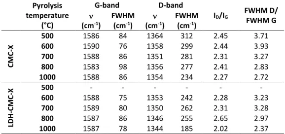
their area (ID/IG) and FWHM ratios for CMC-X and LDH-CMC-X materials. Pyrolysis temperature (°C) G-band D-band ID/IG FWHM D/ FWHM G (cm-1) FWHM (cm-1) (cm-1) FWHM (cm-1) C M C -X 500 1586 84 1364 312 2.45 3.71 600 1590 76 1358 299 2.44 3.93 700 1588 86 1351 281 2.31 3.27 800 1583 98 1356 277 2.41 2.83 1000 1588 86 1354 234 2.27 2.72 LDH -C M C -X 500 - - - - 600 1588 75 1353 242 2.28 3.23 700 1589 80 1350 262 2.31 3.28 800 1587 86 1346 255 2.65 2.97 1000 1587 78 1344 185 2.02 2.37
The trend observed in ID/IG ratio and the decreasing in FWHM ratio (Table 1) are
in consonance with the transition from an amorphous carbon structure, with significant sp3 carbon amount, to more ordered graphitic structures rich in sp2 carbon. Taking into
account Ferrari and Robertson50 ordering trajectory, which relate Raman data with
sp2/sp3 carbon ratio and structure, the intensity ratio between D and G bands is
proportional to the square or the inverse of sp2 cluster diameter, respectively attributed
to: (i) the conversion of amorphous structures to nanocrystalline graphite, with an ID/IG
increasing as observed for LDH-CMC pyrolyzed from 600 to 800 °C; and (ii) conversion of nanocrystalline graphite to graphite, with an ID/IG decreasing as evidenced for
LDH-CMC-1000. In other words, as suggested by evaluated parameters, i.e. bands position, width and area ratio, as higher is the pyrolysis temperature value, there is an increase in the amount of condensed aromatic rings. In agreement, the splitting of the broad band at 2500 cm-1, attributed to poor organized materials, in D+G and 2D bands in
LDH-CMC-1000 spectrum, strengthen the hypothesis of more ordered graphitic material at higher pyrolysis temperature values, as reported in the literature.49,51
The less pronounced G and D bands in Raman spectrum of LDH-CMC-500 material compared to CMC-500 reinforces that organic polymer decomposes at higher
temperature values, even considering a possible low amount of non-intercalated polymer moiety. Furthermore, D-band in LDH-CMC-X series is narrower and shifted to low frequencies (1350 cm-1) when compared to CMC-X counterparts, suggesting a higher
organization degree of carbon chain promoted by the presence of LDH in the precursor material.
Textural properties were evaluated by N2-adsorption/desorption and the
associated isotherms are reported in Fig. S4, ESI†. According to International Union of
Pure and Applied Chemistry (IUPAC) guidelines,52 the isotherms of CMC-X materials
series (Fig. S4a, ESI†) can be classified as a mixture of types Ia and IVa, revealing the presence of micro- (< 2 nm) and mesopores (2 – 50 nm) in their structures. Capillary condensation in mesopores is emphasized by hysteresis, classified as H4 type, which is present in isotherms of materials showing micro-mesoporous carbon aggregates.52
Applying the model developed by Brunauer-Emmett-Teller (BET), the obtained specific surface area (SBET) is equal to 31 and 492 m² g-1 for CMC pyrolyzed at 800 and 1000 °C,
respectively. The huge increase in the SBET value can be justified by the decomposition
of a sodium carbonate crystalline phase (Fig. S5, ESI†), activating the carbon and unblocking pores.
On the other hand, isotherms of LDH-CMC samples (Fig. S4b, ESI†) pyrolyzed up to 800 °C are classified as type I while curve of LDH-CMC-1000 is like that one of CMC-X series. SBET values for materials pyrolyzed at 800 and 1000 °C are equal to 168 and 135
m2 g-1, respectively. Even though there is a change from microporous to
micro-/mesoporous material, the impact in surface area value is not so significant, what can be related to the presence of oxides and metallic particles size and how they are dispersed into the carbonaceous matrix.
XRD patterns of pyrolyzed LDH-CMC-X materials (Fig. 6) are associated with the
in situ recorded patterns (Fig. 4), evidencing the peaks related to reflections of Ni0 fcc
phase. For the material pyrolyzed at 500 °C, besides peaks corresponding to a remainder LDH phase at 36 and 63°, a broad peak around 43° can be attributed to a combination of (200) and (111) reflections of poor crystalline nickel oxide and metallic phases. As the pyrolysis temperature increases, diffraction peaks become narrower and more intense, pointing out the conversion of oxide into metallic phase with a larger crystallite size. Moreover, diffraction peaks at 37, 44 and 63° confirm the presence of remaining NiO crystalline phase in the material. For in situ HT-XRD experiments, the precursor LDH-CMC was kept in an isotherm for one hour before each measurement, while LDH- LDH-CMC-X samples were obtained by fast cooling after reach the chosen temperature value. Therefore, distinct conditions have affected the crystallite size of pyrolyzed materials through a kinetic control. A low intensity diffraction peak around 26° in LDH-CMC-1000 diffractogram is attributed to (002) reflection of ordered graphitic carbon,53 as already
suggested by Raman spectrum (Fig. 5b).
Fig. 6 XRD patterns of LDH-CMC-X materials. Inset shows an expanded region for a clear
view of the reflection peaks.
Transmission electron micrographs (Fig. 7) show the evolution of the materials structure and particles dispersion according to the pyrolysis temperature. For LDH-CMC-500, few spherical particles with a size of about 5 nm are identified, but as higher is the
pyrolysis temperature, there is an increase on their population, until the extensive coalescence of these metallic particles when heated at 1000 °C. Unexpectedly, the average diameter of the particles decreases from 9.06 (600 °C) to 6.32 nm (700 °C), although the size distribution of the last one is more homogeneous (Fig. 7). After LDH dehydroxylation and CMC decomposition, probably there is a mixture of metallic and oxide particles with different densities and volume/diameter ratios. Once the densities of NiO and Ni0 (fcc) are 6.67 g cm-3 and 8.90 g cm-3,54 respectively, the progression on
the reduction of oxide particles with the temperature rising could explain this anomalous behaviour. The result is also supported by Medford et al. experiments,55
which showed the decrease in particles size after reduction of NiO hollow nanospheres into nickel metallic nanoparticles. At 800 °C, the particles size distribution amplifies and the average size increases, in agreement with higher extension of reduction reaction
resulting in larger Ni0 particles.
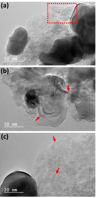
Fig. 7 TEM micrographs and particles size distribution of LDH-CMC pyrolyzed at 500 (a),
Besides metallic particles, chemical transformations also change the structure of the carbon obtained from decomposition of polymer moiety in LDH-CMC, as already suggested by Raman and N2-isotherm
data. From 500 to 800 °C, few graphitic layers surrounding nickel particles are noticed (see red arrows in Fig. 7). This fact is corroborated by the extensively reported catalytic graphitization promoted by metallic, alloys or inorganic compounds particles onto/into carbon substrates.56
Once diffusion of metallic nanoparticles in a substrate is a kinetic process that depends on parameters such as particles size, mobility, adhesion to a surface and temperature,57 coalescence of Ni0
particles is pronounced on the sample pyrolyzed at 1000 °C, although minor particles are still observed, as evidenced by dotted rectangle in Fig. 8a. Graphitic pathways promoted by metallic particles migration (Fig. 8b) have already been reported by Anton58
for nickel nanoparticles deposited onto amorphous carbon films in
temperature values above 600 °C. Thus, for materials pyrolyzed below 1000 °C, the graphitic layer acts on the control of the size of Ni0 particle, as an additional diffusional
barrier to their coalescence, as already reported for nickel,59 gold60 and silver61 particles.
On the other hand, the metallic nanoparticles favour the graphitization of the structure and also the production of carbonaceous structures with different morphologies (ribbon and spheres), as the carbon nano-onions shown in Fig. 8c. Presence of these nanoforms
(a)
(b)
(c)
Fig. 8 TEM micrographs of LDH-CMC-1000
pointing out spherical particles (a), graphitization pathway (b) and carbon nano-onions structures (c).
could explain the change in N2-isotherm profile according to the pyrolysis temperature
and the emergence of mesoporous in LDH-CMC-1000 (Fig. S4b ESI†).
Thermal treatment of pyrolyzed samples in air
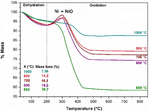
As above discussed, the pyrolysis temperature is a pivotal parameter in the control of the structure and properties of produced carbon/metallic particles. A clear evidence of the temperature influence is the changing in the thermal decomposition profile of pyrolyzed materials in oxidative atmosphere (Fig. 9).
Fig. 9 TG curves (in air atmosphere) of LDH-CMC-X samples. Data inserted present mass
loss for each material in oxidation step (200 – 900 °C).
As previously discussed, the materials obtained after LDH-CMC pyrolysis are mainly composed by carbonaceous structures, nickel nanoparticles and Ni2+/Al3+ mixed
oxides. Calcination of these composites in air causes both carbon and nickel oxidation processes, which involve steps of mass loss (release of COx species) and mass gain
(formation of NiO), respectively. Namely, the decreasing in mass loss percentages (200 – 900 °C) as higher the pyrolysis temperature (X value in Fig. 9) follows the tendency expected regarding an increase in Ni MNP amount. The LDH-CMC precursor is not fully decomposed when pyrolyzed at 500 °C, as evidenced by Raman spectrum (Fig. 5) and XRD pattern (Fig. 6) of LDH-CMC-500 material. Therefore, mass change involved in H2O
and COx release due to the material decomposition in air overlaps mass gain associated
to nickel nanoparticles oxidation. In the TG curves of materials pyrolyzed between 600 and 800 °C, there is an increase in mass in the 200 – 300 °C range followed by an abrupt mass loss (Fig. 9), indicating that MNP oxidation begins before the decomposition of the carbonaceous structure. On the other hand, the TG curve of LDH-CMC-1000 material, besides absence of mass gain, presents a less pronounced slope, as a result of a higher amount of nickel in the sample. In addition, there is also a greater overlap with carbonaceous structures decomposition event, once (i) there is a remarkable increase in metallic particles size (Fig. 8) that can shift the nickel oxidation to higher temperature values and reduce its catalytic effect in carbon structure decomposition; and (ii) carbon matrix is more organized and poorer in oxygenated groups, delaying its decomposition.
Once oxidation of species containing carbon, oxygen and hydrogen leads to gaseous products, the residual mass (mresidual) after thermal analysis experiment refers
to NiO and NiAl2O4 phases, as evidenced by the XRD pattern of the residues obtaining
from the thermogravimetric analysis of pyrolyzed materials in air (Fig. S6, ESI†). Hence,
mresidual can be expressed as the summation of NiO (from Ni0 oxidation; abbreviated
NiONi) and mixed oxides (moxides) from LDH decomposition (NiOLDH and Al2O3), as shown
in Equation 1. The chemical formula of spinel phase was split in terms of nickel and aluminium oxides for clarity purposes.
𝑚𝑟𝑒𝑠𝑖𝑑𝑢𝑎𝑙 = 𝑛𝑁𝑖𝑂𝑁𝑖. 𝑀𝑁𝑖𝑂+ 𝑛𝑁𝑖𝑂𝐿𝐷𝐻. 𝑀𝑁𝑖𝑂+ 𝑛𝐴𝑙2𝑂3. 𝑀𝐴𝑙2𝑂3 (1)
where n is de number of mole and M is the molar mass.
Considering the Ni/Al molar ratio (R) unchanged after pyrolysis of LDH-CMC (Equation 2), the mass of Al2O3 can be calculated from Equation 3.
𝑛𝑁𝑖𝑂𝐿𝐷𝐻+ 𝑛𝑁𝑖𝑂𝑁𝑖
2 .𝑛𝐴𝑙2𝑂3 = 𝑅 (2)
𝑚𝑟𝑒𝑠𝑖𝑑𝑢𝑎𝑙
𝑀𝐴𝑙2𝑂3+ 𝑀𝑁𝑖𝑂.2𝑅. 𝑀𝐴𝑙2𝑂3= 𝑚𝐴𝑙2𝑂3 (3)
Therefore, the content of major chemical components in LDH-CMC-X materials can be mathematically estimated because the carbon and the metallic nickel amounts are known. Elemental analysis indicates a carbon percentage (m/m) at about 13 – 14 %
for all LDH-CMC-X materials (Table S1 ESI†). However, the metallic Ni content cannot be determined by chemical analysis once the materials have also nickel oxide phases. Thus, the quantification of zero-valent Ni was performed using the magnetization saturation values (see Fig. S7 ESI†) compared to the value of pure nickel (55.1 emu g-1),considering
its ferromagnetic characteristics (Table S1 ESI†).62 This method neglects possible effects
of MNPs size and confinement into carbonaceous matrix,62,63 providing an
underestimated nickel content. Hence, considering the percentage of Ni (m/m) for the estimative of NiONi mass, the contents of Ni, NiO and Al2O3 calculated from equations
(1) – (3) are presented in Fig. 10.
Fig. 10 Estimated content of LDH-CMC-X main components in function of pyrolysis
temperature value: carbon (C) was determined by chemical analysis; metallic nickel (Ni) was estimated through magnetization curves; aluminium and nickel oxides (Al2O3 and
NiO, respectively) were calculated using equations (1) – (3).
There is a progressive increase in Ni percentage and, consequently, a decrease in NiO amount as higher the pyrolysis temperature; at temperature values lower than 800°C, the mass of metallic Ni is minor than the mass of NiO, indicating the presence of a high amount of poor crystalline oxide in the matrix embedding metallic particles. However, as previously mentioned, the amount of metallic nickel quantification was estimated considered the saturation magnetization (Ms) of the samples concerning the
nickel in the bulk form (Table S1 and Fig. S7 ESI†). Hence, the total amount of MNPs is underestimated because the Ms values are influenced by particle size and confinement effects.64,65 While a progressive increase of nickel NP in the pyrolyzed products is noticed
as the temperature rises, the carbon amount is unchanged (Fig. 10), evidencing the role of another species in the reaction. Due to experimental setup, the crucible position into the furnace favours a pyrolysis atmosphere rich in gases evolving from LDH-CMC decomposition, including the reducing agent carbon monoxide. Similarly, Al2O3 mass
percentage is also almost constant, once Al3+ species are not reduced in the conditions
used in this work.46 Taking into account the total mass of Ni, carbon, NiO and Al 2O3, it
represents 89% of the LDH-CMC-600, which increases to 95% in LDH-CMC-1000. This change can be attributed to the removal of oxygenated and hydrogenated groups remainder from CMC decomposition, as the pyrolysis temperature increases. As the loss of these groups results in a decrease in total mass of composites, it compensates the loss of carbon and contribute for a virtual unchanged carbon percentage.
Summing up, LDH-CMC thermal behaviour supports its potential application in the synthesis of new nanocomposites owing to the cooperative combination of inorganic (LDH) and organic (CMC) moieties. Regarding this, Ni2+ species can be
transformed to metallic nanoparticles which act as catalysts in the graphitization of carbonaceous structures, while CMC leads to graphitic structures that hinder the nanoparticles coalescence, allowing to control their sizes. Fig. 11 illustrates the thermal processes and compounds involved in LDH-CMC decomposition according to the pyrolysis temperature value.
Fig. 11 Representative scheme of LDH-CMC pyrolysis illustrating: dehydrated structure
(a); beginning of decomposition step producing Ni MNP, mixed metal oxides (MMO) and amorphous carbon (b); growth of Ni MNP and progression of CMC carbonization process and (c); final nanocomposite containing mainly larger nickel MNP and carbon nanoforms (d).
It is worth to mention that materials obtained between 600 and 800 °C hold interesting properties for application in electrocatalysis. Due to their nanometre size, the homogeneous and well dispersed MNPs have a high surface-to-volume ratio, which is able to enhance catalytic performance once there is a larger percentage of surface atoms available to interact with substrates.66,67 Additionally, the MNPs are embedded
in a carbonaceous matrix containing: (i) an amorphous moiety, which is the support to the MNPs and can act as adsorbent to substrates; and (ii) graphitic structures which are able to increase the material conductivity, decreasing the overpotential through more efficient electron transfer processes.68 Hence, the synthetic approach herein reported is
in consonance with green chemistry principles, once can overcome methods for materials preparation that require steps for MNP dispersion on the substrate using organic solvents, as well the addition of other structures to improve conductivity.69,70
Conclusions
The thermal decomposition of LDH-CMC under N2 atmosphere was investigated
by thermal analysis and X-ray diffractometry under heating, disclosing the occurrence of a carbothermal reaction and, consequently, the formation of nickel fcc phase.
Characterization of the corresponding pyrolyzed materials, LDH-CMC-X, revealed that they are composed by nickel nanoparticles, mixed metal oxides, amorphous and graphitic carbon. Summing up, temperature is a pivotal parameter in the synthesis of nanocomposites through the pyrolysis of LDH-CMC hybrid material, once it influences the carbothermal reaction, the graphitization and the coalescence of metallic nanoparticles. In this regard, while MNP catalyse carbon graphitization, the produced shell protects the nanoparticles from aggregation, keeping their size, shape and distribution homogeneous. The bottom-up approach proposed in this work showed that nickel-based LDH intercalated with a polymer derived from cellulose yields inorganic nanocomposites comprising carbon nanoforms and MNP suitable to be explore in fields demanding conductive and catalytic properties, such as electrocatalysis.
Conflicts of interest
There are no conflicts to declare.
Acknowledgments
This work was supported by Fundação de Amparo à Pesquisa do Estado de São Paulo (FAPESP 2011/50318-1, 2014/04816-8, 2018/15201-5), Conselho Nacional de Desenvolvimento Científico e Tecnológico (CNPq 305446/2017-7) and Coordenação de Aperfeiçoamento de Pessoal de Nível Superior (Capes PROEX 0487/1328746). The authors also acknowledge Laboratório de Espectroscopia Molecular (Instituto de Química - USP) for the Raman spectra recording, Laboratório de Cristalografia (Instituto de Física - USP) for the XRD diffractogram registration, Laboratório de Materiais Magnéticos (Instituto de Física - USP) for the magnetic properties measurements, Central Analítica (Instituto de Química – USP) for the elemental chemical analysis, and Institut de Science des Matériaux de Mulhouse staff for experimental measurements.
Notes and References
1 L. Wu, Z. Xi and S. Sun, in Studies in Surface Science and Catalysis, Elsevier B.V., 1st edn., 2017, vol. 177, pp. 123–148.
2 L. Lv, Z. Yang, K. Chen, C. Wang and Y. Xiong, Adv. Energy Mater., 2019, 9, 1803358 (1–7).
3 F. Lu, M. Zhou, Y. Zhou and X. Zeng, Small, 2017, 13, 1–18. 4 P. Anastas and N. Eghbali, Chem. Soc. Rev., 2010, 39, 301–312. 5 F. Cavani, F. Trifirò and A. Vaccari, Catal. Today, 1991, 11, 173–301.
6 J. Yu, Q. Wang, D. O’Hare and L. Sun, Chem. Soc. Rev., 2017, 46, 5950–5974. 7 A. Chatterjee, P. Bharadiya and D. Hansora, Appl. Clay Sci., 2019, 177, 19–36. 8 L. P. F. Benício, R. A. Silva, J. A. Lopes, D. Eulálio, R. M. M. dos Santos, L. A. de
Aquino, L. Vergutz, R. F. Novais, L. M. da Costa, F. G. Pinto and J. Tronto, Rev. Bras.
Cienc. Do Solo, 2015, 39, 1–13.
9 M. Xu and M. Wei, Adv. Funct. Mater., 2018, 28, 1–20.
10 D. Pan, S. Ge, J. Zhao, Q. Shao, L. Guo, X. Zhang, J. Lin, G. Xu and Z. Guo, Dalt.
Trans., 2018, 47, 9765–9778.
11 Z. Li, J. Liu, Y. Zhao, G. I. N. Waterhouse, G. Chen, R. Shi, X. Zhang, X. Liu, Y. Wei, X.-D. Wen, L.-Z. Wu, C.-H. Tung and T. Zhang, Adv. Mater., 2018, 30, 1800527 (1– 8).
12 Y. Zhao, B. Zhao, J. Liu, G. Chen, R. Gao, S. Yao, M. Li, Q. Zhang, L. Gu, J. Xie, X. Wen, L.-Z. Wu, C.-H. Tung, D. Ma and T. Zhang, Angew. Chemie Int. Ed., 2016, 55, 4215–4219.
13 A. Ota, E. L. Kunkes, I. Kasatkin, E. Groppo, D. Ferri, B. Poceiro, R. M. Navarro Yerga and M. Behrens, J. Catal., 2012, 293, 27–38.
14 M. Q. Zhao, Q. Zhang, W. Zhang, J. Q. Huanag, Y. Zhang, D. S. Su and F. Wei, J. Am.
Chem. Soc., 2010, 132, 14739–14741.
15 M.-Q. Zhao, Q. Zhang, J.-Q. Huang and F. Wei, Adv. Funct. Mater., 2012, 22, 675– 694.
16 G. Abellán, E. Coronado, C. Martí-Gastaldo, A. Ribera and J. F. Sánchez-Royo,
Chem. Sci., 2012, 3, 1481–1485.
17 S. Yang, L. Wang, S. Yue, X. Guo, Y. Song and J. He, RSC Adv., 2013, 3, 16990– 16993.
18 S. Zhang, Y. Zhang, W. Jiang, X. Liu, S. Xu, R. Huo, F. Zhang and J.-S. Hu, Carbon, 2016, 107, 162–170.
19 X. Tan, S. Liu, Y. Liu, Y. Gu, G. Zeng, X. Cai, Z. Yan, C. Yang, X. Hu and B. Chen, Sci.
Rep., 2016, 6, 1–12.
20 X. Tan, Y. Liu, Y. Gu, S. Liu, G. Zeng, X. Cai, X. Hu, H. Wang, S. Liu and L. Jiang, J.
Environ. Manage., 2016, 184, 85–93.
21 S. Wang, B. Gao, Y. Li, A. R. Zimmerman and X. Cao, RSC Adv., 2016, 6, 17792– 17799.
22 C. He, X. Han, X. Kong, M. Jiang, D. Lei and X. Lei, J. Energy Chem., 2019, 32, 63– 70.
23 J. Sun, H. Liu, X. Chen, D. G. Evans, W. Yang and X. Duan, Adv. Mater., 2013, 25, 1125–1130.
24 S. Zhang, F. Yao, L. Yang, F. Zhang and S. Xu, Carbon, 2015, 93, 143–150.
25 X.-B. Cheng, G.-L. Tian, X.-F. Liu, J.-Q. Nie, M.-Q. Zhao, J.-Q. Huang, W. Zhu, L. Hu, Q. Zhang and F. Wei, Carbon, 2013, 62, 393–404.
26 Q. Wu, W. Li, J. Tan, X. Nan and S. Liu, Appl. Surf. Sci., 2015, 332, 354–361. 27 T. Raj kumar, G. Gnana kumar and A. Manthiram, Adv. Energy Mater., 2019, 9,
1803238 (1–12).
28 Y. Jiang, Y. Wang, D. Zeng, Y. Xiao, H. Wang, X. Zhang and X. Dai, Microporous
Mesoporous Mater., 2018, 272, 222–231.
29 B. A. T. Mehrabadi, S. Eskandari, U. Khan, R. D. White and J. R. Regalbuto, in
Advances in Catalysis, Elsevier Inc., 1st edn., 2017, vol. 61, pp. 1–35.
30 L.-K. Wu, Y.-X. Zhu, M. Liu, G.-Y. Hou, Y.-P. Tang, H.-Z. Cao, H.-B. Zhang and G.-Q. Zheng, Int. J. Hydrogen Energy, 2019, 44, 5899–5911.
31 J. Masa and W. Schuhmann, ChemCatChem, 2019, 11, 1–14.
32 P. R. Yaashikaa, P. Senthil Kumar, S. J. Varjani and A. Saravanan, Bioresour.
Technol., 2019, 292, 122030 (1–11).
33 G. Singh, K. S. Lakhi, S. Sil, S. V. Bhosale, I. Kim, K. Albahily and A. Vinu, Carbon, 2019, 148, 164–186.
34 S. J. Mills, P. S. Whitfield, A. R. Kampf, S. A. Wilson, G. M. Dipple, M. Raudsepp and F. Favreau, J. Geosci., 2013, 57, 273–279.
35 D.-H. Park, S.-J. Hwang, J.-M. Oh, J.-H. Yang and J.-H. Choy, Prog. Polym. Sci., 2013,
38, 1442–1486.
36 M. Yadollahi, H. Namazi and S. Barkhordari, Carbohydr. Polym., 2014, 108, 83–90. 37 L. M. Ilharco, A. R. Garcia, J. Lopes da Silva and L. F. Vieira Ferreira, Langmuir,
1997, 13, 4126–4132.
38 L. T. Cuba-Chiem, L. . Huynh, J. Ralston and D. A. Beattie, Langmuir, 2008, 24, 8036–8044.
39 M. Yadav, K. Y. Rhee and S. J. Park, Carbohydr. Polym., 2014, 110, 18–25.
40 A. A. P. Mansur, F. G. de Carvalho, R. L. Mansur, S. M. Carvalho, L. C. de Oliveira and H. S. Mansur, Int. J. Biol. Macromol., 2017, 96, 675–686.
41 J. T. Kloprogge and R. L. Frost, J. Solid State Chem., 1999, 146, 506–515.
42 T. Taubner, A. Synytsya and J. Čopíková, Int. J. Biol. Macromol., 2015, 72, 11–18. 43 C. Matei Ghimbeu, B. Zhang, A. Martinez de Yuso, B. Réty and J.-M. Tarascon,
Carbon, 2019, 153, 634–647.
45 D. de Britto and O. B. G. Assis, Thermochim. Acta, 2009, 494, 115–122.
46 University of Cambridge, The interactive Ellingham diagram, http://www.doitpoms.ac.uk/tlplib/ellingham_diagrams/interactive.php,
(accessed 12 December 2019).
47 U. Holzwarth and N. Gibson, Nat. Nanotechnol., 2011, 6, 534–534. 48 A. C. Ferrari and J. Robertson, Phys. Rev. B, 2000, 61, 14095–14107. 49 A. C. Ferrari, Solid State Commun., 2007, 143, 47–57.
50 A. C. Ferrari and J. Robertson, Philos. Trans. R. Soc. London. Ser. A Math. Phys.
Eng. Sci., 2004, 362, 2477–2512.
51 M. W. Smith, I. Dallmeyer, T. J. Johnson, C. S. Brauer, J.-S. McEwen, J. F. Espinal and M. Garcia-Perez, Carbon, 2016, 100, 678–692.
52 M. Thommes, K. Kaneko, A. V. Neimark, J. P. Olivier, F. Rodriguez-Reinoso, J. Rouquerol and K. S. W. Sing, Pure Appl. Chem., 2015, 87, 1051–1069.
53 C. J. Thambiliyagodage, S. Ulrich, P. T. Araujo and M. G. Bakker, Carbon, 2018,
134, 452–463.
54 J. A. Dean, Lange’s Handbook of Chemistry, McGRAW-HILL, INC., 15th edn., 1999. 55 J. A. Medford, A. C. Johnston-Peck and J. B. Tracy, Nanoscale, 2013, 5, 155–159. 56 A. Ōya and H. Marsh, J. Mater. Sci., 1982, 17, 309–322.
57 M. José-Yacamán, C. Gutierrez-Wing, M. Miki, D.-Q. Yang, K. N. Piyakis and E. Sacher, J. Phys. Chem. B, 2005, 109, 9703–9711.
58 R. Anton, Carbon, 2008, 46, 656–662.
59 S. Das, A. Jangam, Y. Du, K. Hidajat and S. Kawi, Chem. Commun., 2019, 55, 6074– 6077.
60 W. Zhan, Y. Shu, Y. Sheng, H. Zhu, Y. Guo, L. Wang, Y. Guo, J. Zhang, G. Lu and S. Dai, Angew. Chemie Int. Ed., 2017, 56, 4494–4498.
61 M. A. Asoro, D. Kovar and P. J. Ferreira, Chem. Commun., 2014, 50, 4835–4838. 62 T. Ishizaki, K. Yatsugi and K. Akedo, Nanomaterials, 2016, 6, 172.
63 Y. Oumellal, Y. Magnin, A. Martínez de Yuso, J. M. Aguiar Hualde, H. Amara, V. Paul-Boncour, C. Matei Ghimbeu, A. Malouche, C. Bichara, R. Pellenq and C. Zlotea, J. Appl. Phys., 2017, 122, 213902 (1–8).
64 X. He, W. Zhong, C.-T. Au and Y. Du, Nanoscale Res. Lett., 2013, 8, 446 (1–10). 65 A. Martínez de Yuso, J.-M. Le Meins, Y. Oumellal, V. Paul-Boncour, C. Zlotea and
C. Matei Ghimbeu, J. Nanoparticle Res., 2016, 18, 380 (1–14). 66 Y. Tang and W. Cheng, Nanoscale, 2015, 7, 16151–16164.
2019, 3, 956–991.
68 P. Trogadas, T. F. Fuller and P. Strasser, Carbon, 2014, 75, 5–42. 69 B. E. Hayden, Acc. Chem. Res., 2013, 46, 1858–1866.