THE DESIGN OF LINEAR ACCELERATORS
J. C. SLATER
TECHNICAL REPORT NO. 47
SEPTEMBER 2, 1947
RESEARCH LABORATORY OF ELECTRONICS
MASSACHUSETTS INSTITUTE OF TECHNOLOGY
The research reported in this document was made possible
through support extended the Massachusetts Institute of
Tech-nology, Research Laboratory of Electronics, jointly by the Army
Signal Corps, the Navy Department (Office of Naval Research),
and the Army Air Forces (Air Materiel Command), under the
Signal Corps Contract No. W-36-039 sc-32037.
MASSACHUSETTS
INSTITUTPE
OF TECOINOLOGY
Research Laboratory of Electronics
Technical Report No. 47
September
2, 1947
THE
I
SIGN OF LINEAR ACCELERAVORS
by
- Table of Contents and Abstract
-Introduction.
1
The linear accelerator is compared to other machines for
acceler-ating electrons and positive ions. References to other accelerator
programs, and acknowledgments, are made.
1. Properties of Periodically Loaded Waveuides.
5
The phase velocity in an unloaded waveguide is greater than the
velocity of light, but by loading, for instance with irises, the
velocity can be reduced to less than that of light,
so
that the
waves can travel with the same speed as a particle, and continually
give energy to it. At the same time, other Fourier components are
introduced, traveling with different velocities, and of no use in
an accelerator. The loaded guide has bandpass filter characteristics.
2. Fourier Resolution of the Field, Modulation Coefficient. and Transit Time
13
Correction.
The use of a single Fourier component of the field in discussing
particle acceleration is mathematically equivalent to making
cor-rections for modulation coefficient and transit time, which do not
have to be handled separately with the present method of treatment,
3. Group
Velocity
in the Loaded
Guide.
14
The group velocity, or velocity of energy propagation,
is
less than
the phase velocity, and can be found from the type of plot used in
Section 1. The group velocity goes to zero as the width of the
pass bands goes to zero, or as coupling between successive cavities
vanishes with the closing of the holes in the irises.
4. Attenuation in the Guide.
16
The attenuation of a traveling wave is connected with the group
velocity, and with the unloaded
of the terminated guide treated
as a resonant cavity. An important quantity is the attenuation
length, the distance in which a traveling wave falls to l/e of its
initial strength.
5. Power Innut to the Guide.
17
Power fed into the guide is dissipated in the walls, and, for a
traveling wave, in an absorbing termination. A formula is set
up for the amplitude of the accelerating field in a standing-wave
tube, as a function of power input, Q of the cavity, and wavelength.
For a traveling-wave, with additional loss in the termination, the
accelerating field is smaller, by an amount which is computed. The
transient build-up of the power is quite different in the two cases,
and depends on whether the guide
is
long or short compared to the
attenuation length. The time taken to build up full excitation in
the tube is comparable with that required for a disturbance to
travel the attenuation length,
so
that the distance between
suc-cessive feeds to the guide must not be greater than the attenuation
length.
6. Geometrical Factors Affecting Acceleration.
The efficiency of acceleration is discussed, as it depends on wavelength, geometry, choice of mode of operation, and use of
standing versus traveling wave. A comparison of expected per-. formance of the M.I.T., Stanford, and Berkeley accelerators is given.
7. Inuut Inmedace of Standing-Wave ad ravein-Wave Tubes. 29
A standing-wave accelerator shows many resonant frequencies in each of the pass bands, while a traveling-wave accelerator shows no such resonant structure. The separation of resonant fre-quencies in the standing-wave case depends on group velocity and total length.
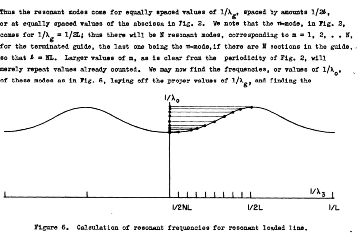
8. The Secial Case of the n-Mode Tube. 31
The n-mode tube, used in the M.I.T. accelerator, theoretically has zero group velocity, and zero attenuation length. Closer examination shows that the effective attenuation length is finite but small.
9. feeding of Power into Linear Accelerators. 33
It is difficult to feed power into an accelerator long compared to the attenuation length, for power must be fed in at many points along the accelerator, and the power sources must be locked in phase by some circuit external to the accelerator. The two
pos-sibilities are discussed of feeding from power amplifiers, in which case the phase is determined from the primary signal, and from
self-excited oscillators, in which the oscillator must be phased by an external phasing signal.
10. Power Feed from a Self-Excited Oscillator. 35
The frequency of a self-excited oscillator depends on the impedance of the load. The operation of such an oscillator into a resonant load, like that of the standing-wave accelerator, is discussed and it is shown that the load stabilizes the oscillator frequency. An external phasing signal operates as an additional load impedance, whose value depends on the phase of the oscillator with respect to
the signal. It can lock both frequency and phase of the oscillator
to those of the signal, if the signal is strong enough.
l1. Tolerances in the Long Accelerator. 41
A very long accelerator, such as must be used for accelerating very high energy particles, would have to have the electromagnetic wave match the velocity of the particles, to a high degree of accuracy. It is possible to adjust a standing-wave accelerator to the required accuracy, by subdividing it into short sections, and tuning each section by use of a comparison signal. A similar adjustment of a traveling-wave tube would be difficult, and frequency control of the oscillators of a traveling-wave tube would be difficult if self-excited oscillators were used, though not with power amplifiers.
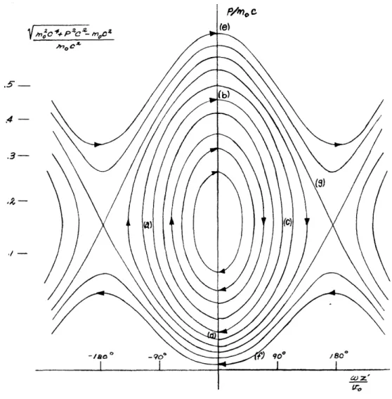
12. The Dynamics of Particles in the Accelerator. 44
The relativistic motion of a particle along the direction of travel of a sinusoidal traveling wave is discussed. If the wave travels slower than the velocity of light, some of the particles form bunches, oscillating about stable positions in the traveling wave, and having on the average the same velocity as the wave. Other
groups of particles travel faster or slower than the wave, and are not locked to it. With a wave traveling with the velocity of light, some particles are locked to the wave, asymptotically approaching a fixed phase, in which they continually gain energy. In a wave whose velocity increases to match the acceleration of particles, stable bunches are formed, as in the first case, but now about positions corresponding to acceleration of the particles. As the velocity approaches that of light, the bunches decrease in size.
13. Amlication of Electron Dyamics to Different T.ves of Accelerators. 56 In the M.I.T. accelerator, electrons will be injected at two million
electron-volts energy, into a tube where the velocity equals that of light, so that many particles will be locked to the wave in asymptotic phases, continually gaining energy, In some other project, including the positive-ion accelerator, particles are injected at lower
velocity in a tube whose velocity increases, resulting in stable accelerated bunches.
14. The Dynamics of Transverse Motion and ?ocussing. 58
In case stable bunches of particles are formed, a focussing instabil-ity is necessarily present. This defocussing is not met in the M.I.T. accelerator, for it vanishes at the velocity of light, as the
stability of bunches also vanishes. In electron accelerators with injection at less than the velocity of light, and subsequent acceler-ation, defocussing is present while the velocity is increasing, but can be easily counteracted by a longitudinal magnetic field. In
positive-ion accelerators, however, the defocussing effect can be
very serious. In addition to the defocussing of particles displaced
from the axis, there can be spreading of the beam on account of the spread of directions in the injected beam. It is shown that for an electron accelerator this spreading is not serious.
THE DESIGN OF LINEAR ACCELERATORS
The linear accelerator is a device for accelerating electrons or positively charged particles to a high energy, by the application of an alternating rather than a direct field, and in a straight line, rather than in an orbit curved by a magnetic field as in the cyclotron, betatron, or synchrotron. Its essential principle is some form of loaded waveguide, in which an oscillating field of high amplitude can be set up, which can be analyzed into traveling waves, one of which travels with the velocity of the particle
to be accelerated. Particles in the correct phase can then remain always in the phase of the traveling wave corresponding to acceleration, and can pick up energy continually, ust as if they were in a constant field. If the properties of the field are arranged to vary, as the particle goes along the tube, so as to keep step with the acceleration of the particle, energies of any amount can in principle be acquired.
The main advantages and disadvantages of the linear accelerator are obvious from its form. As advantages, we may list the saving of the expense of the large magnet, which is necessary in the circular machines; the fact that the size and expense of the machine is roughly proportional to the final energy of the particle, rather than to a higher power of the energy, as in circular machines, suggesting that at least for very high energies it may be a more economical device than the circular machines; and the fact that
the particles will automatically emerge in a well-collimated bean, whereas beam ejection is one of the principal difficulties in the circular machines. The principal disadvantage of the linear accelerator is the fact that an individual particle, instead of passing through the same alternating field again and again, and using the same power source and accelerating gaps many times, as in the cyclotron and other circular machines, must pass through a succession of alternating fields and a succession of power sources. This multiplicity of sources and fields results in expense, in a large duplication of high'-frequency equipment; in complication, in the construction of a very long and elaborate
tube with its adjacent power sources; and in a design difficulty, in the adjustment of the phase of the oscillating field over a great length of accelerator, so as to insure that the field will stay in step with the particles.
There is another design difficulty not shared by the circular machines, which does not appear until one makes a little mathematical analysis. In any accelerator, the particles must travel a very long distance, either in a straight line or a circle or a
spiral, before they acquire the energies about which one talks in present discussion of hundreds of millions or billions of electron-volts. In this very long path, they are likely to spread from their ideal path, and become lost to the beam. The spreading can be
of two sorts. First, they can spread laterally, or be defocussed. Secondly, since the operation of all these devices except the betatron depends on having the particles bunched longitudinally, in bunches a wavelength apart, in the proper phase of a traveling wave to be accelerated, the particles can spread longitudinally, getting ahead or behind their bunches, and can be debunched. Now in the cyclotron and synchrotron, those particles
which are in the correct phase to be bunched and accelerated are also in the right phase to be focussed, so that stability is automatic. On the other hand, in the linear accelerator, particles in the phase for bunching and acceleration are defocussed. This defocussing imposes a design problem of serious proportions for the linear accelerator.
It is too early to evaluate completely the advantages versus the disadvantages
and difficulties of the linear accelerator. If the circular machines in the billion-volt range were perfectly easy to build, there would be no question butthat they would be the preferred devices, because the disadvantages and difficulties of the linear accelerator, as
Just enumerated, are formidable. But all the recent thinking about circular machines has shown that their difficulties are formidable as well. Among electron accelerators, present thinking indicates that the synchrotron is preferred to the betatron for energies more than a few hundred million electron-volts, but the synchrotron is believed to face a practical limit, on account of radiative losses by the electrons, at about a billion electron-volts. No device except the linear accelerator has been suggested to go beyond this range. As for proton and other positive ion accelerators, the ordinary cyclotron meets relativistic difficulties at about a hundred million electron-volts. The frequency-modulated or
synchro-cyclotron is ideally adapted for energies of several hundred million
electron-volts.2 Attempts at design of higher energy machines of this typ, howeve; show that the dee structure and the magnet design begin to face problems at about six hundred million electron-volts which become very serious indeed at a billion electron-volts, and probably are insurmountable much above that energy.
For the range of several billion electron-volt positive ions, present thinking suggests only one alternative to the linear accelerator: the proton synchrotron, a device in which both magnetic field and frequency are simultaneously modulated, during the cycle of acceleration of the particles, in such a way as to keep the radius of the particle's orbit constant, and yet to keep the particle in step with the radio-frequency field. This has the advantage that only an annular magnet is required, as in the synchrotron, so that the magnet cost does not go up so rapidly with energy as in the synchro-oyclotron, with its solid magnet. Furthermore, the accelerating electrodes, or dees, can be relatively
small, and the frequencies encountered are so low that the frequency modulation is simple. Its difficulties are nevertheless very great. The magnet, even though annular, is
exceedingly large and expensive. The mutual adjustment, in time during the accelerating cycle, of frequency of oscillator and magnetic field, to keep the particles in step with
the accelerating field, must be very accurate, and is probably in principle as difficult
an adjustment as that of the field in the linear accelerator, to keep it in step with the particles. And-there is the further difficulty, not so obvious at first glance, that the
circumference of the orbit is very large, and in all present thinking there is only one accelerating unit around the circumference, which does not supply a very great increment of energy per revolution of the particle. Hence the particle receives much less energy, per unit length of its own path, than in the linear accelerator, where every effort is made to
concentrate the accelerating units and make them as powerful as possible, so as to cut down the total length of the machine. In building up its total energy, then, the particle in the proton synchrotron travels very much further than in the linear accelerator, and as
-2-a result the ch-2-ances of spre-2-ading, str-2-aggling, -2-and loss of particles from the beam are much greater, so that it is likely that the number of particles lost from the beam will be even greater in the proton synchrotron than in the linear accelerator, even in spite of the inherently defocussing nature of the latter device, which we have mentioned above.
When we consider these difficulties in the way of attaining very high energies by other means, we are likely to feel, and the writer feels, that the linear accelerator cannot be dismissed without careful discussion, though it is by no means obvious that there will be any range of energies in which it is superior to other types of machines. All the work carried on so far has been preliminary and exploratory, in the range of a few million electron-volts. The writer has no doubt but that the linear accelerator can be made to work successfully in this range, but it is also not clear that it has any advantage over circular machines for low-energy particles. For this reason, the primary emphasis of the design considerations suggested in the present paper is on the possiblility of extending the machine to very high energies. We shall constantly be looking for dif-ficulties that will appear at high energies, though they will be absent at low energy. We may as well state at the outset that, while some of these difficulties appear serious, we can at least suggest possible means of overcoming them. It is obvious that, before start-ing the very expensive construction of a high-energy linear accelerator, all these dif-ficulties should be examined as far as they can be in preliminary tests, so that there is a reasonable assurance of success. Many of these tests have already been made, but not all, and some of them will be taken up in the body of the paper.
The linear accelerator is not a new device. Sloan3 and others in the decade before the war worked, with moderate success, on similar instruments. The production of high-energy, high-frequency power sources such as the magnetron during the war, however, has given the possibility of feeding enough power into a linear accelerator, operating as a pulsed device, so as to promise really high accelerations, and to make it a promising field for further work. Two main lines of development have resulted since the war, closely related to each other, and both really sterming from radar work. First, Alvarez,5 at the University of California, has been working on the design of a positive ion accelerator, working at a frequency of about 200 megacycles, using radio-frequency equipment designed for radars of that frequency. Secondly, a number of laboratories have been working on electron accelerators, using high-power magnetrons, generally at about 10 cm wavelength,
developed for radar purposes. It is such a program that has been carried out at the
Massachusetts Institute of Technology, under the auspices of the Research Laboratory of Electronics.6 This program has been supported by the Joint Service Contract No. W-36-039 so-32037 of the Signal Corps with the Research Laboratory of Electronics. It is a fairly direct outgrowth of thinking that was prevalent in the M.I.T. Radiation Laboratory during the latter days of the war, but the actual work and detailed thinking about design have all been carried on since the establishment of the Research Laboratory of Electronics. Other
7
similar programs in this country are at Stanford University, the General Electric Co., the University of Virginia, Purdue University, 8 Yale University,9 and a number of others. Outside the country, there are two ambitious programs in England, at the Telecommunications Research Establishment (TR), 10 and at the Cavendish Laboratory in Cambridge, a program at
-3-the Polytechnic Institute of Mexico, and various o-3-ther projects. As far as -3-the writer is aware, the general thinking in all these projects is along similar lines, with few dif-ferences of opinion of any moment. Reports have been available to the writer from
Stanford7 where Hansen and his collaborators have made important advances, and from TREE1 0 where a theoretical group under Walkinshaw, and experimental groups, have made elaborate and complete surveys of the problem. In many respects similarities will
appear between the treatment of the present paper and those of the groups just mentioned. The present work has been in almost all respects carried out independently at M.T.T., in the course of the last two years, and since the work of Stanford and TE is only avail-able in the form of private reports, it has seemed wise to make the present paper complete,
even though there might appear to be duplication between it and those of the other groups. The project at M.I.T. is an experimental as well as a theoretical one, devoted to exploration of the design factors to be encountered in a large accelerator, and to the building of an experimental section to accelerate electrons to energies of the order of twenty million electron-volts. It is still far from this goal, and its progress is described in the Quarterly Progress Reports of the Research Laboratory of Electronics.6 Nevertheless, the general theory seems to be in good enough shape to warrant publishing the present paper at this time. On completion of the M.I.T. project, an experimental paper will be published by the group concerned, discussing the results of the project. It can be stated in the meantime that many of the points mentioned in the present paper have been checked experimentally, and many more will be before the completion of the project.
Naturally the writer is indebted to many colleagues and friends for discussions of the problem. First comes the group at M.I.T., consisting of Prof. A. . ip, Dr. Winston H. Bostick, a group of Research Associates consisting of Messrs. R. J. Debs, P. T. Demos, L. C. Maier, S. J. Mason, and J. R. Terrall, and several members of the mechanical and technical troup, including Mr. I. J. Polk and Mr. M. Labitt. Former mem-bers of the group were Dr. Jules Halpern, now of the University of Pennsylvania, who made important contributions during its earlier stages, Mr. . Everhart, and Mr. R. A. Rapuano, We have profited by discussions with other members of the staff of M.I.T., including Prof. J. G. Trump, and are particularly indebted to Prof. J. A. Stratton and Prof. A. G. Hill, Director and Associate Director of the Research Laboratory of Electronics, for their constant friendly interest. The Technical Advisory Committee of the services associated with the Research Laboratory of Electronics, consisting of Messrs. Harold A. Zahl, E. R. Piori, and John E. eto, of the Signal Corps, Office of Naval Research, and Army Air Forces respectively, has taken a lively and much more than formal interest in the project.
Dr. R. Q. Twias, of TBE, assigned to M.I.T. for liaison purposes, has taken a personal interest in the problem, and has contributed to discussions, as well as acquainting us with the progress of the TE project. We have had useful discussions with Drs. W. C. Hahn and L. Tonks and their associates from the General Electric Company, with Prof. J. W. Beams and colleagues from the University of Virginia, with Prof. L. Alvarez and his colleagues
of Berkeley, and Prof. W. W. Hansen and his colleagues from Stanford University, as well as with various other workers in the field. The writer is particularly indebted to
Stanford University for the opportunity of spending some weeks there in the summer of 1947,
-4-where most of this paper is being written, and of becoming acquainted with the linear accelerator programs at that University and at the University of California.
1. Properties of Periodically Loaded Waveauides. The phase velocity of a wave in a wave-guide is greater than the velocity of light in free space, so that a particle cannot travel with the same velocity as such a wave, and some more complicated structure must be used to produce the linear accelerator field. The structures in use all consist of periodically loaded waveguides of various types. Accordingly, we shall take up in this section the properties of periodically loaded waveguides, emphasizing the general features which all such guides have in common, more than the peculiarities of individual structures. Much of the theory is of a type familiar to mathematical physicists from many problems of wave propagation in periodic structures, such as the theory of the weighted string, filter theory in electrical engineering, the electronic structure of metals and crystalline solids, and x-ray and electron diffraction. The interrelationships of these probleas are described in
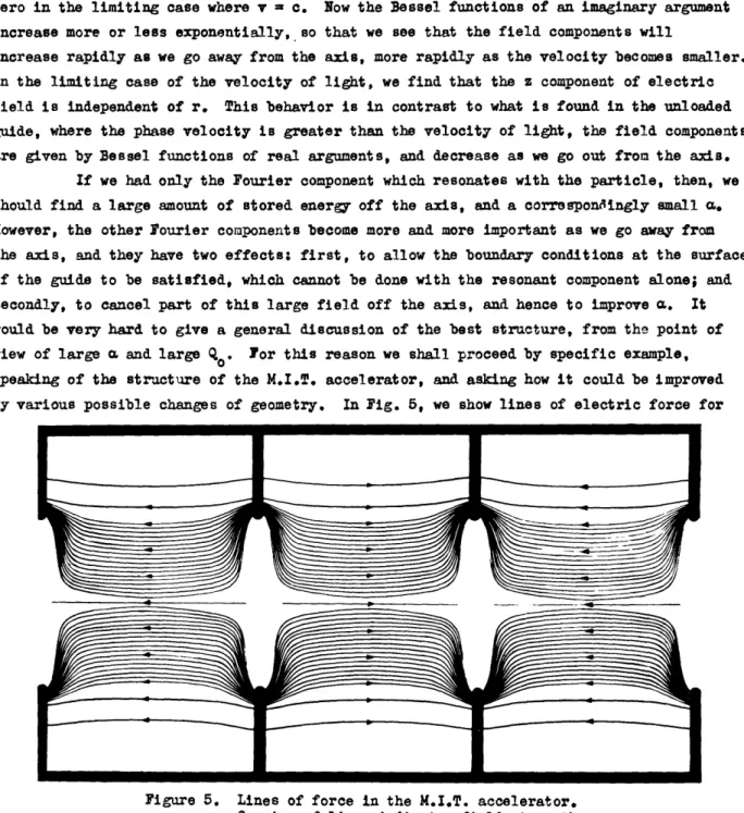
"Wave Propagation in Periodic Structures," by L. Brillouin (McGraw-Hill Book Co., Inc., 1946). Similar methods were used by the writer during the war in discussing the resonant modes of the many-cavity magnetron (touched on briefly in ef. 3.1). Since these general methods are so familiar, we shall give many results in the present section in rather gen-eral language, without proof or detailed discussion. The structures most used are shown
schematically in Fig. 1, in which (a) shows the iris tube, used in most of the microwave
.---- --- -- ---
.---
*
---- -- Figure a.Figure lb. _- *
-5-electron accelerators, including that at M.I.T., and in which (b) shows the structure being used by Alvarez for his positive ion accelerator, When we wish to discuss a spe-cific example, it will be the iris tube, but most of our remarks will apply to Alvarez's structure as well.
The foundation of the study of wave propagation in periodic structures is a theorem called loquet's theorem, which is very simple: in a given mode of oscillation of the structure, at a given frequency, the wave function (that is, in the electromagnetic case, the values of electric and magnetic field) is multiplied by a given complex constant when we move down the structure by one period. The proof of this theorem is not abstruse, and results from the fact that if the whole structure is displaced along its axis, which we take to be the z axis, by one period L, it coincides with the original structure, so that the new wave function can differ from the original one by only a constant factor. Let us write this factor in the form e , where Y is a constant, in general complex. We now notice that a very simple function of z which has this property, namely that of multi-plying the function by e' L when z is increased by L, is simply eY z .
In fact, the most
general function of z with this property is the product of Y with an arbitrary periodic
function of z of period L, which will be unchanged when z increases by L. Such a periodic function can be expressed as a Fourier series, which can be written, in its complex form, as a sum of exponentials exp(-2nmJz/L), where n is an integer, positive or negative, each exponential with an appropriate coefficient. Thus the wave function can be written as a sum of exponentials exp(-Y - 2mnJ/L)z), with appropriate coefficients.
The interpretation of this result depends on the nature of Y. In general, this constant can be complex, but it can be shown that in a structure without energy dissipa-tion it must be real or pure imaginary. If it is real, each exponential decreases with increasing z, aside from its phase change, and we have an attenuated wave. Such waves are not appropriate for accelerator operation. In other cases Y is pure imaginary, and may be written Y = J0o. Then if we define
n o +L ' (1)
we can write our exponentials in the form e . Combined with the factor e t expressing
the complex time dependence of the sinusoidal field, a single Fourier component has the
form eu(wt
form e( ~ t' I~nZ)z) This represents a progressive wave, with angular frequency w, wavelength2n/on, traveling along the z axis with velocity =
*a/p.
We now see that, using (1), thedisturbance can be regarded as a superposition of a great many traveling waves, with a variety of velocities vn, which get numerically smaller for large values of n. Each traveling wave will have an appropriate coefficient or amplitude.
Some one of these traveling-wave components may well be appropriate for use in a linear accelerator. The velocities of many components will be less than the velocity of light, so that the velocity of one component can be arranged to equal the velocity of the particle being accelerated. This component will then resonate with the particle, in the
the particle speeds up enough to get ahead of the wave; we shall take up such questions later). If a particle resonates with one component of the Fourier expansion of the field,
it will not resonate with any other, for the others all travel with different velocities. In fact, as seen from the moving particle, the resonating component acts like a field independent of time, which can then exert effects felt over many periods; but all other components move with respect to the particle with large velocities, so that as far as the particle is concerned they are rapidly oscillating fields. Their effect on the particle will be a rapidly alternating one, which will produce almost no net motion; and for almost
all purposes they can be completely neglected. We have arrived, then, at a very important result: only one component of the field in the periodic structure will travel with the same speed as the particle; it acts like a sinusoidal traveling wave; and in considering the particle's motion, only this traveling wave need be considered. There is, of course, a corollary to this. ach of the components in the Fourier expansion has a finite ampli-tude, and therefore stores energy, and results in energy loss in ase tne walls of the system have a finite conductivity. This expenditure of energy is quite useless for pur-poses of accelerating particles, except for the particular Fourier component that resonates with the particle. Therefore we must look for a type of excitation in which the resonant component has as large an amplitude as possible, in comparison with the other, non-reso-nant components.
To determine the velocity of each component as a function of frequency, and hence to find which one is appropriate for use in the accelerator, we must find 0o, and hence
E,
as functions of w. This is a considerable task, which we shall discuss later. Some general results are easy to prove, however. Let us consider w as a function of 0o. Then we can show easily that the resulting curve is periodic in '0, with period 2/L. For suppose o0 increases by 2n/L. Then, from (1), the quantity which was previously _1 will increase to become equal to the previous 0, and similarly each On will change to equal the preceding n+l' changing the name of each n' but leaving the whole set of Ols unchanged. This makes no change in the physical situation, for we must find the same coefficient for each of the ts that we did earlier for the i which had the same numerical value, and the frequency as determined from the field must be the same. We can also prove easily that the curve of w as a function of 0o is an even function; that is, changing the sign of 0o leaves w unchanged. This fact arises essentially because we can make two successive transforma-tions without changing the physical situation: changing from a wave function to itsconju-gate, which changes each exponential from exp(J(wt - nZ)) to its conjugate exp(-jwt + J z), then changing t to -t, resulting in exp(J(wt nZ)), the net result being to change the sign of all n's, without changing the essential problem, or the frequency.
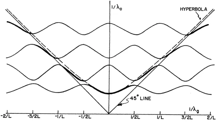
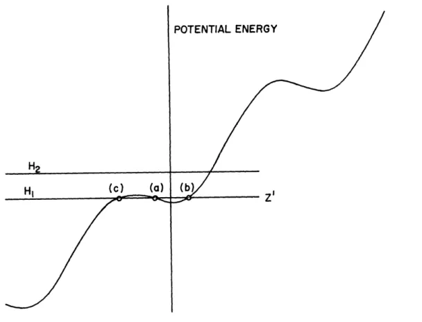
As a result of these general theorems, a plot of w as a function of will have the form shown in Fig. 2. Here it is convenient to plot /2nc = l/o 0 instead of , and
Bo/2m l/Xg instead- of Bo, where c is the velocity of light in free space, )k is the wave-length of the wave in free space, and kg is the guide wavelength associated with the com-ponent of n = O. We see that this guide wavelength cannot be uniquely defined, but that we can add any integral multiple of 1/L to /Xg, and have an equally valid guide wave-length. Otherwise stated, /Xo is a periodic function of 1/kg, with a period 1/L. Now we
-7-I/Xg
Figure 2. Frequency as function of reciprocal guide wavelength, for periodi-cally loaded line. Slopes of radius vectors represent phase veloc-ities of various Fourier components, divided by velocity of light.
see that the phase velocity of the component n = 0, divided by the velocity of light c, is
VO/c
W/BOc
=(I/O)/(l/g). or
is
the
slope of
the radius vector out to a point of the
curve. If this slope is greater than that of the 45o line, the velocity is greater than that of light, and if it is less,the velocity is less than that of light. We can now see graphi-cally the velocities of all the components of different n values associated with a given wave function, by setting up the values of 1/Xg spaced by intervals /L, and drawing the radius vector to each, as is done in Fig. 2. It is clear from this diagram how the com-ponents of higher n value have smaller phase velocities. Also it is clear that there are components with both positive and negative phase velocity, or components traveling both to the right and the left.
We shall now discuss in qualitative language the way in which curves like those of Fig. 2 arise, by using a specific example. 'We take the example of the iris tube, as
shown in Fig. la, and ask how the curves change as the holes in the irises change their size, at constant iris spacing, from holes as large as the iris, (so that the iris does not exist) down through smaller and smaller holes, to the limiting case where the hole vanishes, and the tube consists of a set of cylindrical cavities, separated by conducting walls. This problem will be considered in detail by the writer in a forthcoming paper. We consider only the transverse magnetic mode in which the magnetic field runs in circles about the axis of the circular guide, and the electric field is in a plane containing the axis, and independent of the angle of rotation of that plane about the axis. This is the mode ordinarily met in a cylindrical cavity, in which the electric field runs along the z axis from one wall to the other, being proportional to J(kr), where k = Z/k, and where the magnetic field is proportional to Jl(kr). In the cavity, the resonant frequency is fixed by the condition that must be zero at the outer wall of the cavity, or at r = R, where R is the radius of the cylinder; thus we must have J(2n/ko) - 0. But the first zero of Jo' which is concerned in the mode we are interested in, comes for a value 2.405 of the argument of the Bessel function. Hence the resonance comes for 2n/ko = 2.405, We now
consider a succession of cases with fixed iris spacing, but varying iris openings, related to this mode of the circular cavity.
We start with the case where there are no irises at all, or where the radius a of the iris opening equals the radius R of the cylinder. Then we have an ordinary unloaded waveguide. It is well known that the free space wavelength
n
o and the guide wavelengthXg are related by the equation
-8-1 _ 1
2 2 x
2
o g c
(2)
where Xc is the cutoff wavelength. This latter quantity is determined as the free-space wavelength for which the guide wavelength becomes infinite, or in which the field is
independent of z. In this case, the problem becomes ust like that in the cylindrical cavity which we have ust discussed, so that the cutoff wavelength is the free-space wave-length found in that case, or is given by
2R/Xc = 2.405. (3)
We now see that the relation between /ko and l/%g given by (2) is the equation of a
hyperbola, shown in ig. 3. At values of l/l
oless than l/X
c(that is,
for free-space
wavelengths greater than the cutoff wavelength) the curve indicates no real value of Xg; that is, no real propagation is possible, but there is a pure imaginary wavelength, result-ing in attenuation. For all higher frequencies, the hyperbola lies above the 450 line,LINE
t/X
Figure 3. Hyperbola representing l/Xo vs. 1/g for an unloaded waveguide.
indicating a phase velocity greater than the velocity of light, reducing asymptotically to the velocity of light as the frequency becomes very large. In this case, of course, there is no periodicity in the guide, and consequently no periodicity in the plot of Fig. 3.
A very small iris, however (that is, an iris whose hole radius a is nearly as large as the tube radius R), produces a change in the situation resulting in periodicity,
and we see in Fig. 4 how this can come about. Over most of the range of o, the change of frequency is negligible, but ust in the neighborhood of the value ,0/2LT = 1/2L, the
-9-Figure 4. l/XA0 s. l/kg for slight periodic loading of wavguide. Heavily shaded part of curve corresponds to ig. 3.
change is considerable. This particular value has a simple significance: it corresponds to the situation L = ?y2, or the case where the iris spacing equals a half guide wave-length. Consider now the propagation of a wave of this wavelength down the guide. We may consider that each iris acts as a scatterer, so that a wave approaching an iris results in a reflected wave traveling backward, as well as a transmitted wave. With irises spaced a
half guide wavelength apart, the reflected wave from each successive iris will be a whole
period out of phase from the reflected wave from the preceding iris, since the direct wave will have traveled a half wavelength farther, and so will the reflected wave. Thus all these reflected waves can interfere with each other, and can produce a large effect. As a matter of fact, they interfere so strongly that no direct wave at all can be propagated through a lossless guide of infinite length of this sort; the reflected wve proves on analysis to equal the incident wave in amplitude, and a pure standing wave is set up. This is the phenomenon which, in the study of x-ray diffraction, becomes Bragg reflection.
The situation becomes clearer when we consider the amplitudes of the various
Fourier components of propagation constant n' in this problem. Let us assume that Bo/2n
equals the value of n/2f nearest to the reciprocal of the guide wavelength that a guide
without irises would have for the corresponding frequency. Then for most frequencies or
f's, only one Fourier component in the expansion of the field will be appreciable, that associated with o0. We readily find that, for positive Io s, the wave reflected from the
irises is characterized by n = -1, and waves that have made multiple reflections are given
by other values of n. Unless the interference conditions we have mentioned in the
constructive interference between waves reflected from the various irises, and the Fourier component associated with n = -1 will be small, and all the others even smaller. As we approach our critical value of o/2fm = 1/2L, however, the amplitude of the component n = -1 becomes large, equalling the amplitude of the component n = 0 at the critical value. As we pass beyond this value, the amplitudes of other components than n = 0 again become small. At the value 0/2T = 3/2L, where the iris spacing is three half wavelengths, we again get interference, and the building up of a reflected wave, this time corresponding to n = -3;
and so on.
We now consider the periodic nature of the cruves of Fig. 4. The part of the curve drawn with a heavy line refers to the frequency as a function of 0o which we have described in the preceding paragraph, departing from the hyperbola characteristic of the waveguide without irises only in the neighborhood of the critical values given by o/2T = m/2L, where m is an odd integer. At each of these critical values, the curve proves to
have a break, there being two possible frequencies associated with the same guide
wave-length. These two frequencies can be shown to be associated with two modes, both standing
rather than traveling waves (on account of the fact that a progressive wave under these conditions is completely reflected), and one of sine-like, the other of cosine-like, character, so that for one of the waves the irises come at nodes, for the other at anti-nodes; it is natural that the irises have different effects on the frequency in these two positions. For frequencies lying within these breaks, thereis no possible propagated mode, but the value of o0 becomes imaginary, or there is an attenuated wave. The range of fre-quencies is broken up, in other words, into certain pass bands of frequency, in which we can get propagation, with bands of attenuation between. The periodically loaded line acts like a bandpass filter, with an infinite number of pass bands; and in case the loading reduces to zero, and we get the case of Fig. 3, the bands coalesce, so that all frequencies greater than the cutoff frequency of the unloaded guide can be propagated.
On account of the periodicity of the curve of frequency vs o, of which we have already spoken, we see that the curves of Fig. 4 should be drawn in a periodic way, as we have done. The branch of the curve which is drawn heavily, as we have already seen, is the one which reduces to the hyperbola of Fig. 3 in the limiting case where the irises disappear, but the other branches are equally legitimate. They correspond to different conventions for the numbering of the ls. -So far, we have named that component which had the largest Fourier component o. These other branches correspond to numberings in which the component for n = 0 has small amplitude, but some other component has a large amplitude. In this problem, one numbering, the one we used originally, is far more natural than any other; but when the iris becomes more important, the distinction is no longer clear, many Fourier components being large, and some of these other methods of numbering are equally reasonable.
When we look at the curves of Fig. 4, we see that now, in contrast to Fig. 3, we can have a phase velocity less than the velocity of light. The curves are of the form already discussed in Fig. 2, and we know that for any frequency in one of the pass bands, we can find an infinite number of velocities, one associated with each intersection of the curve with the straight line = constant. Each of these velocities is that of a particular
-11-Fourier component, however, and the only -11-Fourier component which is large is that
represented by the heavy line in ig. 4, which still, over most of its length, lies above the 450 line, and corresponds to a velocity greater than that of light. In other words,
though the irises have introduced Fourier components of low velocity into the Fourier resolution of the field, these components have small amplitude, for a small iris, and would not be effective components to use in a linear accelerator.
The situation is different, however, when the iris projects further into the tube; that is, when the ratio a/R is smaller, where a is the radius of the hole in the iris. In this case, the curve is more like that of Fig. 2. The curve can become so depressed that the velocity of the Fourier component of largest amplitude can become less
than that of light. Furthermore, the amplitudes of other Fourier components increase so much, on account of the large scattering by the irises, that other Fourier components of lower velocity have considerable amplitudes. These two effects are of course related; and while we now have components of considerable amplitude with velocities suitable for a
linear accelerator, there is a compensating disadvantage, in that other components have considerable amplitude as well and they absorb power, which is useless as far as the accelerator is concerned. For instance, suppose we have loaded the guide so much that the so-called n-mode (that is, the mode in which the phase difference BoL from one section to the next is rT; this corresponds to ol/2 = 1/2L , or the critical value for reflection) has a velocity less than the velocity of light, and we use that mode. Then we have already seen that we have a reflected wave of amplitude equal to the direct amplitude, which is of no use, so that the power used to set up this reflected wave is thrown away. Or suppose we use the
n/2-mode,
for which OL = -/2, o/2n = 1/4L. In this case, as we see from the figure,-we shall have to load even more heavily to bring the velocity of this mode down below that of light, the amplitudes of other Fourier components traveling in the same direction as the wave will become considerable, and we shall throw power away in them. In any case we paya penalty for slowing the wave down, the penalty being greater the greater the slowing down.
The limiting case is that in which the hole in the iris vanishes altogether. Then the guide becomes a set of disconnected cylindrical cavities, each oscillating like a
single cavity. To set up modes corresponding to different values of ,o' we merely arrange to have the phases of the oscillation differ from cavity to cavity by o L. The frequency will be independent of o, so that in this limit the curves of w vs to degenerate to horizontal lines, and the pass bands have shrunk to zero. The allowed frequencies, or
frequencies of these limiting pass bands, are easily found; they are ust the resonant frequencies of the cylindrical cavity. The lowest one is given by Eq. (3), and oor-responds to the lowest pass band; the higher ones correspond to the cases in which the
disturbance varies sinusoidally along the length of the cavity, the tangential component of E having nodes at both plane walls of the cavity, so that the length L equals an integral number of half wavelengths. In this limiting case, we can find easily the Fourier resolution of the field, and the magnitude of the various Fourier components, and these limiting values hold approximately for irises with very small holes, a<< R. Thus for instance in the lowest pass band, the value of the z component of field is approximately
-12-constant in each cavity, and equal to eJ o p L in the pth cavity. All we have to do to get the Fourier components is to expand this simple step function in tiLe wag we have already
described.
2. Fourier Resolution of the Field, Modulation Coefficient, and Transit Time Correction. We have stated in the preceding section that, to handle the operation of the loaded guide as a linear accelerator, we need only consider the Fourier component of the field which resonates with the particle, or has the same phase velocity. If we consider only this component, the particle remains in a fixed phase relation to It, is acted on by a con-stant force, and the dynamical problem is very simple. On the other hand, various writers on the subject proceed by a different method, familiar from conventional analyses of triodes and klystrons: they consider the effect of the finite transit time of particles between the two sides of the cavity. Suppose for instance that the iris hole is small; then the two irises are similar to two grids of a triode or klystron, and the field between them is approximately a constant, independent of z, but of course varying sinu-soidally with time. As a particle moves from one to the other, the field cannot remain at
its peak value for the whole transit; for it is varying with time. If we calculate the aver-age force acting on the particle, we find that it is the peak value, multiplied by a certain coefficient, which in the language of klystron theory is called a modulation coefficient, equal to unity if the grids are so close together that the transit time is zero, but decreasing as the transit time increases, being a function of the form (sin x)/x of the transit time. This function can go to zero for certain transit times, or go negative, and such effects are encountered in the theory of high-frequency operation of triodes, where transit time becomes important.
We shall now show that this modulation coefficient or transit time effect is not a new effect which we must handle separately, but that in fact our procedure of using a
single Fourier component is itself an elegant way of making the transit time correction. Suppose our particle is traveling along the z axis with a velocity v, so that its position is given by z = vt. Let the value of z, the longitudinal component of electric field, as a function of z and t along the z axis, be
E
=
2F ej
w(
t- z/Tn),
where is the amplitudev the velocity, of the nth Fourier component in the analysis of
the field. As the particle moves, the field will .change with time, and we can take account of this by substituting for the time t when the particle is found at position z the value t = z/v. Thus the field acting on the particle at the point z is
2 n e 4 l/) - (l/vn z
n
The average of the nth term, averaged over z (assuming the particle is traveling for a long distance) is zero if v is different from vn, since the resulting sinusoidal function
-13-will average to zero. Thus the average field -13-will be zero unless the velocity of the particle equals the velocity of one of the Fourier components, and in that case it will be Just the , or amplitude of that Fourier component. It is to be noticed that this result is only correct if the particle is traveling for a long distance at constant velocity in the field; this condition is approximately, though not exactly, met in the linear accelera-tor, and deviations from it do not enter in a way to affect our subsequent arguments.
We see, then, that our procedure of Fourier analysis is all that we need to do to take account of the transit time of the particles from cavity to cavity or iris to iris. This result, we notice, is quite general, and not dependent on the fact that we are using a waveguide loaded by irises, but applicable to any periodic structure. Any modification of the structure which results in an increase of the amplitude of the Fourier component which resonates with the particle will have an effect which can alternatively be described as improving the modulation coefficient or transit time situation. Our method, however, is much more general than the conventional argument in terms of transit time, in that that argument is often set up only for the case of a constant field between parallel grids or electrodes, whereas our method is correct for an arbitrary variation of longi-tudinal field with z. It is possible, as a matter of fact, to adapt our method, not for periodic structures, Bout for single grid systems, as in the triode or klystron, by the use of Fourier integrals instead of Fourier series. One can then prove familiar theorems about modulation coefficients and transit time, and as we shall see later about the trans-verse motions of particles and focussing. We shall not make further use of this fact, however.
3. Group Velocity in the Loaded Guide. In Section 1, we have shown that the ratio of the phase velocity of the wave in a loaded guide, to the velocity of light, is given by the slope of the radius vector out to the point representing the wave, in the graph of
(1/ko) vs (l/kg). Now we shall consider the group velocity, which we shall call vg, and show that it is given, not by the slope of the radius vector, but by the slope of the tangent:
v d(l/ )
cZ = * (4)
We shall find the group velocity to be important in the study of power flow in the guide, and in the question of how much power dissipation we must have to set up a field of a given strength.
The conventional derivation of the formula for group velocity sets up a super-position of two waves, one with angular frequency w and propagation constant , the other
with angular frequency w +Aw and propagation constant +A8, and considers the velocity
of the beats between these two waves. It is easy to show (see for instance Slater and Frank,"Mechanics' McGraw-Hill, New York, 1947, p. 168) that this velocity is given by AWA. This is closely related to the slope of the plot of the type given in Fig. 2. The
abscissa in
that figure is /xg
=
/2rr, the ordinate /%.
=
w/2c, we see that
beatv elocit
= ~(1
(5)
If the frequencies and propagation constants of the two waves are close together, we can replace the quantity (5), which is the slope of the chord, by the slope of the tangent to the curve, getting a common velocity of beat propagation for all waves of neighboring
fre-quencies. This is the roup velocity, as given by (4).
We may now set p a group of waves, such for instance as a wave train of finite length, by superposing sinusoidal waves of a variety of frequencies or wavelengths, the
necessary band of wavelengths or frequencies being narrower, the longer the packet is in space or time. If the curve of 1/xO vs l/kg can be considered to be straight over this range of wavelength or frequency, the beat velocity as defined in (5) will be the same for all pairs of waves in the wave train, and the whole pattern will move forward with a single velocity, the group velocity. If on the other hand the wave train is too short, so that its Fourier analysis extends over a wide range of frequencies or wavelengths, the beat velocities of different pairs of components will be different, the pattern will not be
preserved, and the disturbance will spread in a complicated way.
The group velocity is the velocity with which energy is propagated in the guide. This is most easily seen by considering a finite wave train, of definite length, traveling say to the right. The energy crossing a given cross section of the guide, per unit time, will then clearly be the energy contained in a length
vg
of the guide, since ust thisenergy will pass the cross section in a second. Thus we have a relation between the Poynting's vector as integrated over a cross section of the guide (the energy flux) and the energy density per unit length in the guide: the energy flux is vg times the energy density per unit length.
As we look at the curves of / o0 vs l/kg, as in ig. 2 and Fig. 4, we see that
the slope of the curves is in every case less than unity, so that the group velocity is less than the velocity of light, as we expect from relativistic arguments. Furthermore, we see that as we approach the w-mode, the slope becomes horizontal, and the group velocity goes to zero. This is consistent with statements which we have made already about the n-mode. We saw earlier that as we approach that mode, the reflected wave becomes stronger,
until the -mode itself is a standing wave, with equal amplitudes for direct and reflected waves. In this case, there is no net flow of energy, so that vg is zero. Near the WT-mode, the reflected wave almost equals the direct wave, there is small energy flux, and
consequently the group velocity must be very small. Furthermore,we see that if the holes in the irises are small, the whole band of frequencies will shrink, so that even in the v/2 mode, where the group velocity has its maximum value, the group velocity will still be very small. In the limit, as the holes shrink to zero, and the frequency becomes
independent of the guide wavelength, the group velocity will approach zero as well. This is obviously consistent with the fact that, with vanishing holes in the irises, there can be no flow of power.
-15-4. Attenuation in the Guide. So far we have been neglecting attenuation in the guide; but it plays an essential part in the operation of the linear accelerator, and we must next consider its effect. If we have a given energy density within a short section of loaded guide, therewill be a flow of energy into the walls of the guide, on account of the
resistive losses in the walls. We can relate this loss of energy to the unloaded Q of the
guide, which we shall Qo. This is defined by the relation
_ enerv issiation er second _issi gn Der sec in walls (6)
QO w x stored energy
It is the Q which the guide would have if it were converted into a resonant cavity by perfectly reflecting end plates, so that no energy would be dissipated in the ends. Since
the energy dissipation per second in the walls, and the stored energy, are both
propor-tional to the length of the section of guide we are considering, we see that is inde-pendent of the length.
If we now have a traveling wave flowing down the guide, its power will be attenuated as it travels down the guide; for some of its energy will be drained off into the losses in the walls. We can easily find the rate of attenuation resulting from this. Let us set up an equation of continuity for the energy flow. If W is the energy per unit length in the guide, S the energy flux across a given cross section, D the power dis-sipation per unit length in the wall, then the equation of continuity states that the time rate of increase of W equals the negative of the divergence of S, minus the power dis-sipation D. That is, since S will depend only on z, the distance along the guide, we have
+
S + D = o.
(7)
at 6z
We have ust seen from (6), however, that D = wW/Qo; and from the preceding section we have seen that S = v W. Thus (7) becomes
+
a
+-
0 , a +v as+
S0
(8)Assuming a steady state, so that the time derivatives are zero, we find
S-2/e o _
S =S0 ' o = W
Thus the flux is attenuated, with an attenuation constant /lto, where o, the distance in which the flux falls to l/e of its value, may be called the attenuation length. The at-tenuation represented by this expression must be applied to the fields as found in
Section 1; the electric and magnetic fields separately will have attenuation coefficients half as great as the flux.
-16-The attenuation length may be interpreted easily in terms of the time required for an oscillation in a resonant cavity to die down to 1/s of its initial value. In a resonant section of waveguide, there will be no variation of energy density with ; thut the derivatives with respect to z in (8) must be set equal to zero. Then we shall find
-(W/q)t
W Wo e
showing that the energy density falls to l/e of its initial value in a time Q0/w. We now see that the attenuation length is ust the distance which the energy will travel, moving with the group velocity, in the time in which the energy density falls to 1/e of its initial value, a time which we shall call T0 . The attenuation length, then, becomes
greater as Qo becomes greater, but it becomes smaller as the group velocity decreases. We shall find that the attenuation length is a very important concept in the discussion of linear accelerators. We shall call a linear accelerator long if its length is large compared to the attenuation length, short if its length is short compared to the attenuation length. It is clear that long accelerators will involve us in difficulties. Any signal introduced at one end of the accelerator will be attenuated to negligible amounts by the time it reaches the other end, and if we start building up a signal at one end at a
given time, this signal will not even have reached the other end by the time To, at which the field at the first end will have built up to its steady state value (for the build-up of energy naturally has the same time constant as the decay). This situation means that the two ends of a long accelerator are effectively decoupled from each other, both in space and in time. Yet we shall find that to set up a proper field in a long accelerator we must have definite phase relations between the fields at its two ends. This imposes problems
of excitation, which we must consider; for it appears that if we wish accelerators long enough to produce particles with energies in the billions of electron-volts, the acceler-ators must be long in the sense in which we are using the word.
5. Power Input to the Guide. To operate a linear accelerator, we must build up a very strong electric field along the z axis, associated with the Fourier component traveling with the same velocity as the particle to be accelerated. If we know the whole pattern of the field within the accelerator, we shall find the integral of the square of the electric field per unit length of the accelerator, and hence the stored energy per unit length, to be proportional to the square of this field component. In fact, if the electric field along the z axis has the component
ejW(t - /v)
associated with the resonant wave, we must have the stored energy per unit length equal to a constant times
Eco2
times the cross section of the guide. For a given geometrical shape (that is, given iris spacings, dimensions, etc.) but arbitrary scale, the cross section will be proportional to the square of the free space wavelength at which the-17-accelerator is operated, since all linear dimensions of the cavities will be proportional to the wavelength. Thus we have
W = A o o0 '
where A is a constant which can be determined when the field distribution is known. It is assumed above that W is the total stored energy, which of course is twice the electrostatic energy.
To produce a large value of E, then, we must have a large stored energy, and hence, in a steady state, a large dissipation of energy, and a large amount of power fed into the accelerator. During the build-up process, W will be less than in the steady
state. Hence the accelerating field I will be less during buildup than in the steady state, and the proper way to operate the accelerator is to let the field bild up first, then introduce the particles to be accelerated, when the field has reached substantially its final value. We shall consider in this section the amount of power which must be fed in in the steady state, to produce a given field E, and shall also consider the transient process of building up the steady state.
The results are somewhat different, depending on whether the accelerator is closed with perfectly reflecting walls at the ends, so that a standing wave is set up in it, or whether the ends are terminated with non-reflecting or matching resistances, so that traveling waves will not be reflected from the ends. They are also somewhat different depending on the distribution of power inputs along the length of the accelerator. Let us start with the case of reflecting end walls, and uniform distribution of power sources along the tube, as in the M.I.T. and Berkeley accelerators. In this case, all the power fed into unit length will be dissipated in power loss in unit length of walls. We have already seen that this dissipation is wW/Qo . Hence, if the power fed in per unit length
is P, we have
2 2
P = q
Remembering that
w/c
=2n/X
, c
=1/
, and
=377 ohms,
we find
J
so
where a,
, (9)9
We note that the accelerating voltage per unit length is proportional to the square root of power per unit length; thus if we wish to have an accelerator producing a given vol-tage as short as possible, or to make as large as possible, we wish to feed in as much power as possible per unit length. On the other hand, if the total power at our disposal is fixed, or if we wish to economize on power sources, we should go to the other extreme, and make the accelerator as long as possible. Te see this fact, we rewrite (9) in a form
to give the total voltage acquired by a particle, UZ, where is the total length of the accelerator, in terms of P, the total power input. We have
377 (P&)Qo£
showing that the total voltage is proportional to the square root of the length, so that by making the length indefinitely large, we can in theory get any amount of acceleration
from a fixed power input.
from the equation ust written, we see that a given amount of total voltage can be produced either by using a large amount of total power and a short length, or a small power and large length, and that the total voltage is a function of the product of total power and length. There seems to be no scientific way of deciding what separate values of power and length to use, and therefore the decision will presumably be based on economic
arguments. The cost of a linear accelerator, aside from the fixed cost of end termina-tions, will consist of two parts: the cost of the accelerator tube, pumping, housing, etc., which will be proportional to the length, and the cost of the power sources with their feeds into the accelerator tube, which will be proportional to the power input, and hence, for a definite total voltage, inversely proportional to the length. Hence the cost will be the sum of two parts, one proportional to the length, the other (for a fixed voltage) inversely proportional to the length. We choose the length to minimize the cost. Now the
function x + 1/x has its minimum for x = 1, where both terms are equal in magnitude. Thus
the accelerator will cost l.east if the tube (that is, the parts whose cost is proportional to length) and the power sources cost equal amounts. If a decision has been made as to the type of power source to use, and if the sources are to be equally spaced along the line, the economic way to determine the spacing of sources is to build a length of line whose cost equals that of the power source, We shall see later that the spacing between oscillators must not be large compared to the attenuation length; therefore we must be
sure that our design is such that the economic spacing of oscillators is less than the attenuation length. Presumably by the time the various preliminary accelerator projects now under way in the various institutions are completed, accurate enough cost estimates can be made to find these economic spacings between oscillators, but reliable figures are not yet available, so that it is not clear whether a close spacing of oscillators, as at M.I.T., or a wide spacing as at Stanford, or something intermediate, will eventually turn out to be most economical.
The situation is quite different if we have a traveling wave. Again we assume a fixed power input P per unit length. Nowhowever,power is lost in two ways: there is still a dissipation wW/Qo per unit length on account of resistive losses in the walls, but there
is also a flux v W out through the end of the tube, into the non-reflecting termination. Thus the total power P supplied to the tube must equal (/1% + vg) W. This amounts to