HAL Id: hal-00316714
https://hal.archives-ouvertes.fr/hal-00316714
Submitted on 1 Jan 1999
HAL is a multi-disciplinary open access
archive for the deposit and dissemination of sci-entific research documents, whether they are pub-lished or not. The documents may come from teaching and research institutions in France or abroad, or from public or private research centers.
L’archive ouverte pluridisciplinaire HAL, est destinée au dépôt et à la diffusion de documents scientifiques de niveau recherche, publiés ou non, émanant des établissements d’enseignement et de recherche français ou étrangers, des laboratoires publics ou privés.
Introduction: The Equator-S mission
G. Haerendel, R. B. Torbert, H. Höfner
To cite this version:
G. Haerendel, R. B. Torbert, H. Höfner. Introduction: The Equator-S mission. Annales Geophysicae, European Geosciences Union, 1999, 17 (12), pp.1499-1502. �hal-00316714�
Introduction
The Equator-S mission
G. Haerendel1, R. B. Torbert2, H. HoÈfner1
1Max-Planck-Institut fuÈr extraterrestrische Physik, Garching, Germany 2University of New Hampshire, Durham, NH
Abstract. In spite of its short operational life of only ®ve months, the major goals of the Equator-S mission were ful®lled, except that its contribution to the ISTP science is restricted to the morning sector of the outer magne-tosphere. A set of twelve papers following this intro-duction is a ®rst documentation of the achievements. They span from the successful testing and operation of the most advanced and complex way of measuring electric ®elds in a hot plasma environment by means of electron beams, to various investigations at or near the equatorial magnetopause and in the plasma sheet. 1 Introduction
The Equator-S mission was dierent from most contem-porary scienti®c satellite missions in that spacecraft and mission were designed and developed at a research institute, the Max-Planck-Institut fuÈr extraterrestrische Physik (MPE) with a few items supplied by agencies and industry. Only for mission analysis and operations the German Space Operations Center (GSOC) stepped in. Neither the European nor the German space agency was in the position to accommodate this mission in their regular programs within the desired time frame. Only a low-cost approach, enabled by the past satellite-building experience of MPE, oered a solution and was accepted for funding by the then still existing German Space Agency (DARA) in December 1994. Support promised and subsequently given by ESA and NASA was impor-tant for that decision. This paper will brie¯y review the motivation for this mission, the spacecraft development, the short mission history, and ®nally introduce the subsequent set of twelve papers presenting ®rst results and discoveries.
2 Motivation
The primary objective of MPE emerged from its responsibility for the Electron Drift Instrument (EDI)
on the Cluster mission. EDI uses an electron beam technique to determine the electric ®eld by sensing the displacement of electrons during one gyroperiod. In order to cope with any possible direction of the magnetic ®eld and with its rapid changes, electron gun and detector were designed to allow beam injection and detection into and from any direction within a half sphere. The operation of EDI, i.e., the onboard program for the tracking algorithm, is exceedingly complex. Hence, the EDI team had a high interest in learning to employ this method in space before the launch of Cluster, because it was feared that the learning curve may be rather steep, leading to substantial data losses when ®rst attempted on the four-satellite Cluster mission.
Hence, one was looking for a test ¯ight opportunity. Since return of the beam to the detector is only possible if it is emitted into the plane transverse to the magnetic ®eld with an accuracy better than 0.5°, instantaneous measurements of the ®eld have to be included into the tracking algorithm, and thus the payload had to include a very sensitive and stable magnetometer. The chance of a realization appeared in late 1990, when the general idea of the Equator-S mission was born. But, of course, one would not design a satellite mission just with EDI and a magnetometer. The ®nal mission concept was to contribute substantially to the ISTP program by choos-ing an eccentric equatorial orbit and thus ®llchoos-ing the equatorial gap of that program (hence the name Equator-S, with S for small) and by adding a few key particle instruments. As a third element, all measure-ments, including those of 3D particle distributions, were to be done with the highest possible temporal resolution. To this end, a spin period of 1.5 sec was chosen, which had strong implications on the S/C design.
The search for economical launch opportunities took several years, until by the end of 1994, a launch as Auxiliary Passenger on an Ariane 4 appeared aordable to DARA, and green light was given for this mission. Although, the hope to launch Equator-S before Cluster had meanwhile faded away, the mission was still judged
to be worthwhile because of its contribution to the ISTP. When the launch of Cluster failed in June 1996 and ESA decided to have a recovery Cluster-II mission with a launch in mid-2000, the original primary goal was re-established.
3 Spacecraft development
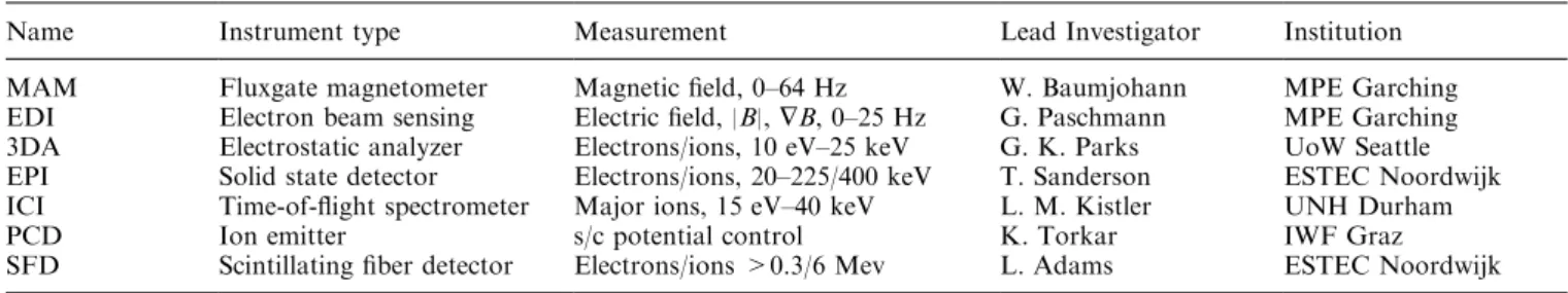
A group of experimenters had gathered around the Equator-S planning team already in early 1991. The core group consisted of participants in the Equator mission of NASA's Global Geospace Science program, a mission cancelled in 1986. But NASA had promised to support these teams, in case an opportunity for replace-ment showed up. When, during the subsequent years, it became a realistic possibility to build a reasonably sized spacecraft, the payload summarized in Table 1 was accepted and an appropriate spacecraft designed. Fur-thermore, two technological experiments (GPS and solar cell diagnostics) were added to the primary payload. Designs and even some instrument hardware were taken from the Cluster and Wind missions. The table also lists the key institutes and some of the actors involved.
The design criteria of the spacecraft were as follows. It had to be built around a solid fuel kick-motor (provided by NASA) needed for injection from geosta-tionary transfer orbit into the ®nal orbit. Various particle detectors and the electron gun-detector units had to be accommodated with their particular viewing conditions. Two magnetometers each were mounted on two rigid 1.8-m booms. The spacecraft surface had to provide space for solar panels providing an average power of at least 60 W. For attitude control and spin-up, magnetic torquing was chosen. This implied the installation of circular and linear coils. They had to be operated in the stronger geomagnetic ®eld near perigee, in order to ®nally achieve stable isolation by rotating the spin-axis out of the orbital plane to perpendicular to the ecliptic plane, a procedure requiring several months. The spacecraft had to ®t into the Ariane 4 passenger capsule and needed altogether ®ve TM antennas in order to cope with all potential visibility constraints from the ground station at Weilheim. A detailed description of the spacecraft was given by StoÈcker et al. (1996).
For the electrical system, cost reasons required that almost exclusively left-over parts of the AMPTE and
Rosat missions were used. The ¯ight system unit was shielded with 8 mm Al against the harsh radiation environment in the eccentric equatorial orbit. The solar panels had highly ecient GaAs cells and were provided and mounted by German industry. In order to achieve a data transmission with minimal contact times with the ground station, a mass memory with 192 MBytes was provided by UNH and funded by NASA.
The spacecraft was developed and built at MPE between January 1995 and September 1997 by a team of about eight persons with involvement of the workshops and other facilities of the institute and of industry. The launch mass was 229 kg. The costs of the spacecraft, including the MPE eort, were approximately 8.5 MioDM. Figure 1 shows the spacecraft with booms not extended. Two major instruments, EDI and ICI (see Table 1), and several antennas on the bottom side are well visible.
4 Mission history
Equator-S was launched on 2 December 1997 from French Guyana as auxiliary passenger on an Ariane 4 together with a Japanese telecom satellite. After spin-up to 48 rpm with help of the torquing system, it was injected into the ®nal orbit by the kick-motor on 11 December 1997. The orbital characteristics are: 497 km perigee, 67275 km height of apogee or 11.5 RE geocen-tric distance, 3.9 degrees inclination, and 22.3-hour period. The commissioning phase lasted into February 1998.
Unfortunately, the mission was damaged by several malfunctions. On 17 December 1997 the primary master processor unit failed, and on 30 April 1998 the second unit experienced the same problem. This caused the premature end of the mission. Failure analysis attribut-ed both events to a latch-up in one the RAM-chips usattribut-ed by the processors. It is not unlikely that deep dielectric charging by the high energetic electron ¯uxes in December 1997 as well as in April 1998 was the cause of the latch-ups. Unfortunately, that part of the processor system had no latch-up protection and for safety reasons no switch-o capability was installed.
Besides the rather short mission duration (a mini-mum of 15 months was planned) a serious instrument failure occurred. In January 1998, the 3D Electron Analyzer suered a sudden failure of all pre-ampli®ers, which was caused by an undetected software error. As a
Table 1. Scienti®c payload
Name Instrument type Measurement Lead Investigator Institution
MAM Fluxgate magnetometer Magnetic ®eld, 0±64 Hz W. Baumjohann MPE Garching
EDI Electron beam sensing Electric ®eld, |B|, ÑB, 0±25 Hz G. Paschmann MPE Garching
3DA Electrostatic analyzer Electrons/ions, 10 eV±25 keV G. K. Parks UoW Seattle
EPI Solid state detector Electrons/ions, 20±225/400 keV T. Sanderson ESTEC Noordwijk
ICI Time-of-¯ight spectrometer Major ions, 15 eV±40 keV L. M. Kistler UNH Durham
PCD Ion emitter s/c potential control K. Torkar IWF Graz
SFD Scintillating ®ber detector Electrons/ions >0.3/6 Mev L. Adams ESTEC Noordwijk
similar problem with the ion sensor was feared, the experimenters decided to leave it switched o, until the cause of the electron analyzer failure was clearly established. This took longer than expected, and when the new ¯ight software was ready to be unloaded at the end of April, the whole S/C had gone out of service. So, the payload complement was operated without the 3D ion/electron detectors, except for one brief period during commissioning. This rendered also the potential control device useless, because it had to be controlled by the measurements of the electron sensor. Mass-resolved 3D-ion measurements were, however, available from the Ion Composition Instrument.
Again for ®nancial reasons, mission operations were designed so that support by the ground station at Weilheim for data dumps was needed for only 3 hours a day, while commanding was scheduled only every third contact period. The capacity of the mass memory allowed 13.5 hours of data storage in low rate and 3.4 hours in high rate telemetry. Therefore, four types of orbit coverage were designed:
1. low rate data coverage starting at about 5.5 RE and extending beyond apogee,
2. similar to (1) but with a low altitude hour of high rate data taking,
3. same as (1) but starting apogee,
4. symmetrical around apogee with 90 min of high rate data.
From time to time perigee data were taken for attitude determination.
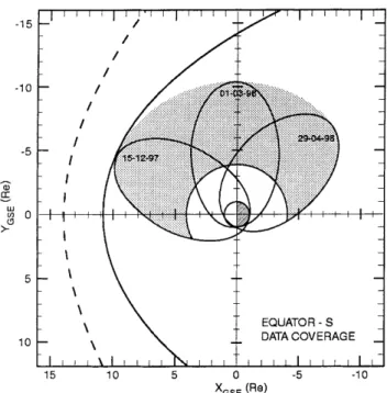
This strategy restrained the Equator-S science to altitudes essentially outside the radiation belts, quite consistent with its payload complement. Figure 2 shows
in GSE X-Y-coordinates the orbits during the active phase of the spacecraft. The region of data coverage is grey shaded.
Standard processing of the Equator-S data is carried out at the German Cluster Science Data Center at MPE, which has taken on also the task of an Equator-S Data Center (EDC). It obtained the telemetry data received and processed at GSOC directly via a leased ISDN line, and also via CD-ROM. With software provided by the instrument teams, the EDC then generates two sets of key parameters, both closely modelled after the Cluster data sets: the Summary Parameter Data Base (SPDB) with 1-minute time resolution, and the Prime Parameter Data Base (PPDB) with 1.5s (i.e., spin) resolution. The SPDB and PPDB contain ion moments, energetic particle ¯uxes, and magnetic and electric ®eld values. A standard set of plots of SPDB parameters is generated at the same time. The EDC also archives the data. Once validated by the Lead Investigators, the key parameters can be obtained via NASA's or MPE's CDAWeb. The one-minute data (SPDB) is available to everybody, while access to the 1.5-s data (PPDB) is initially restricted to the Equator-S Science Team.
5 First results
In spite of the short operational life of the Equator-S spacecraft and its reduced operational payload, all three major objectives named in Section 2 have been ful®lled. The EDI technique has been successfully proven in space ¯ight, the data obtained during the ®ve months of operation will make a substantial contribution to the ISTP, albeit restricted to the morning sector of the magnetosphere, and the high time resolution has been successfully exploited. This is documented in the
fol-Fig. 2. Equator-S operational orbits projected into the GSE X-Y plane. Grey shading indicates the region of data coverage
Fig. 1. The Equator-S spacecraft, booms not deployed. One gun-detector unit of the Electron Drift Instrument is seen left from center, to the right the Ion Composition Instrument. Several antennae on the bottom side are extended
lowing twelve papers of which we will here give a very brief preview.
The papers by Quinn et al. and Paschmann et al. describe the two complementary techniques to measure the electric ®eld by (a) triangulation and (b) time-of-¯ight measurements of the electron beams from two gun-detector units on board the spacecraft. The validity of the techniques in weak and highly variable magnetic and electric ®elds is demonstrated and data of ®elds of only a few tenths of mv/m are presented. So E ´ B-drifts two or more orders of magnitude smaller than the thermal velocity of the ions can be precisely measured. The time-of-¯ight technique, in addition, delivers values of the magnitude of B with an accuracy of better than 1% and can thus be applied to determine magnetometer osets along the spin axis. The amount of valid electric ®eld data obtained during the lifetime of Equator-S is, however, small, because the learning how to operate these complex instruments with their closed-loop con-trol algorithms was quite time consuming. Furthermore, stray ®elds set up by the operation of the magneto-rquers, which was needed during the initial 5 months, compromised the exact pointing of the electron beams in the weak ®elds of the outer magnetosphere. In total, invaluable experience was gained for the operation of the electron drift instruments on the Cluster II mission. Important as baseline instruments and necessary providers of real-time ®eld orientations for the Electron Drift Instrument were the ¯ux-gate magnetometers (Fornacon et al.). They combined a wide dynamic range with high accuracy at frequencies up to 64 Hz and high stability. These excellent properties allowed, for the ®rst time, to determine with ¯ux-gate magnetometers the wave forms of so-called lion roars found typically in the troughs of magnetosheath mirror waves (Baumjohann et al.). Wavelet analysis of a great number of events showed that these electron whistler mode waves exist preferentially in the frequency range of 0.05±0.15 fce (fce= electron gyrofrequency) and propagate almost precisely along the ambient ®eld direction. In the high-beta environment in which they are found to occur, only small temperature anisotropies suce for their excita-tion.
The other contributions in this issue relate to the ISTP. The long dwelling time near the magnetopause gave rise to careful determinations of the position and dynamics of the magnetopause during morning hours (Dunlop et al.) and to a thorough study of the occur-rence and characteristics of mirror modes outside, but close to the magnetopause (Lucek et al.). It is found that the location of the magnetopause scales very well with ram pressure and has mostly rather stable normal vectors. The mirror modes, large amplitude compres-sional structures, are found to be parallel to the magnetopause. Because of lack of plasma measurements in the initial phase, these studies were based solely on the magnetometer data. Fortunately, before the above-described failure of the 3D electron analyzer happened,
valuable measurements of the 3D plasma analyzer and the solid-state telescopes could be performed during multiple crossings of the magnetopause (Parks et al.). The accurate measurement of electrons from 7 to 100 eV was enabled by the operation of the potential control device reducing the spacecraft potential to near zero (Torkar et al.), when normally the energy spectra are contaminated by photoelectrons.
Later in the mission, when Equator-S had its apogee in the morningside plasma sheet, ®eld-aligned very high-beta structures, named plasma blobs, were observed which appear to be the magnetospheric relatives of the well-known mirror modes in the magnetosheath (Ha-erendel et al.). The elucidation of the large scale morphology and motion of these blobs was made possible by simultaneous measurements of the Geotail spacecraft during close conjunctions with Equator-S. Such a conjunction during a substorm extending into the late night sector also allowed to analyze the reaction of the plasma sheet at this late time, in particular the ¯ow reversals upon transits from plasma sheet to the lobe (polar cap) ®eld lines (Nakamura et al.).
Equator-S was instrumented mainly with the goal to study the outer parts and boundary regions of the magnetosphere including the ring current. In the latter region ion composition measurements were made in the recovery phase of a magnetic storm. Changes in the energy spectra of H+and O)were interpreted in the light of charge exchange losses along their energy-dependent drift paths (Kistler et al.). This led to a critical compar-ison of existing electric ®eld models. The last paper in this series describes the ®ndings with a new technique, a scintillating ®bre detector, designed to measure integral ¯uxes of more than 400 keV (Cyamukungu et al.). The whole operation period of Equator-S is covered, and the correlation of the energetic electron belt population with geomagnetic storms is demonstrated.
In summary, Equator-S covers a wide range of aspects, new measuring techniques, detailed studies of the magnetopause, and adjacent magnetosheath, hith-erto unknown structures and dynamics of the morning-side plasma sheet, and investigations of ring current and radiation belts. In view of these initial results (more are to come), one can only deplore the short life of the spacecraft.
Acknowledgements. The spacecraft development was supported by DARA/DLR with grant 50OC94024. The contributions of NASA, ESA and Arianespace to spacecraft, instrumentation and mission are gratefully acknowledged. Particular thanks are owed to the mission analysis and operation teams at GSOC for their excellent service. Furthermore, we are deeply indebted to the spacecraft development team for the dedicated work and creation of a beautiful spacecraft.
References
StoÈcker, J., P. Parigger, and M. Thiel, Structural development of Equator-S, ESA-SP, 386, 21±27, 1996.