Decubitus prophylaxes in surgery:
A novel approach using active load controlled bedding system
D. Hradetzky1, D. Messerli2, S. Harsch3, M. Jeker1, S. Böhringer1, E. Schkommodau11 Institute for Medical and Analytical Technologies, School of Life Sciences, University of Applied Sciences and Arts Northwestern Switzerland, Muttenz, Switzerland, corresponding author: [email protected]
2 Messerli & Partner GmbH, Rubigen, Switzerland
3 was with Institute for Medical and Analytical Technologies, School of Life Sciences, University of Applied Sciences and Arts Northwestern Switzerland, Muttenz, Switzerland
Abstract
Suffering from decubitus ulcer, also known as bedsore, leads to long lasting treatment of the affected region as well as it provides a significant contribution to expenditures in health care. Acquiring a decubitus ulcer during a hospital stay is often related to surgical procedures. Therefore an improvement of the intraoperative situation is eligible. In contrast to common approaches focusing on passive pressure redistribution of the mat a new approach towards an active load con-trolled bedding system is presented. This active support system consists of multiple elements, enabled to change height and detecting the applied load on each element. Due to lowering an overloaded region a decrease of applied load is ex-pected while the load on the surrounding elements will increase.
1
Introduction
1.1 Decubitus ulcer
Decubitus ulcer, known as bedsore or pressure ulcer, is often induced by an increased external local load or pres-sure on tissue. This results in squeezing the tissue towards underlying bones and decreasing or disabling peripheral circulation and perfusion. Typically tissue not protected by muscles or fatty tissue is affected. Therefore anatomi-cally exposed bony regions of the human body like sa-crum, ischium and calcaneus are subjects to an increased risk of developing a decubitus ulcer. According the Euro-pean Pressure Ulcer Advisory Panel pressure ulcer is de-fined as “an area of localised damage to skin and underly-ing tissue caused by pressure, shear friction or a combina-tion of these” [1]. It is internacombina-tionally classified into four classes ranging from “non-blanchable erythema” (class I) up to “full thickness tissue loss” (class IV).
Besides the applied mechanical load on the tissue the du-ration of this is a second major risk factor on developing a decubitus ulcer. Reswick observed an increase of risk at decreased pressure when increasing the exposure period [2]. Therefore bedridden persons with limited movement opportunities are particularly affected. This risky situation is reflected in different scenarios, where prolonged peri-ods of lying down without repositioning the body occur, like in home care or intensive care.
1.2 Social and economic impact
Suffering from decubitus ulcer, leads to long lasting ther-apeutic treatment of the affected region, as the healing is rather poor. It constrains the patients significantly.
Besides the impact on life of the individuals, decubitus ulcer is also a significant clinical and financial issue for health care providers. A decubitus ulcer may cause an ex-cessed length of hospital stay. Graves determined a medi-an prolongation of 4.3 days [3]. The Germmedi-an Robert Koch Institute estimates a financial burden of around 2 billion Euros in 2002 in Germany for the health care system, while other experts estimates the same cost only for class III and class IV decubitus ulcers [4]. For the UK annual costs from 1.4 to 2.1 GBP corresponding to 4% of the to-tal National Health Service (NHS) expenditures where observed [5].
1.3 Decubitus ulcer in OR environment
Besides the home care or intensive care scenario as a risky situation, the operating room (OR) is getting more and more attention. This environment may increase the risk for pressure ulcer, as the patients are kept immobile for long periods of time. Due to anaesthesia procedure the patient are unable to shift their weight, feel pain or to complain [6]. Enhancing the anaesthetic procedure ena-bles surgeons to perform complex and time-consuming interventions, prolonging the period of duration and in-creasing the risk of decubitus ulcer. Approximately 23% of the total numbers of decubitus ulcers developed in hos-pital are intraoperatively acquired [7].
In addition certain anaesthetic agents may decrease the peripheral circulation and perfusion, resulting in an in-creased risk of developing decubitus ulcer [8].
Nowadays strategies to decrease this risk in an operating room environment are limited to reduce the load by opti-mizing the mat materials and pressure redistributing sur-faces [3, 9, 10]. So far no active or controlled pressure regulating system is known.
Biomed Tech 2012; 57 (Suppl. 1) © 2012 by Walter de Gruyter · Berlin · Boston. DOI 10.1515/bmt-2012-4172
Within this paper we present a novel approach for an ac-tive support system, capable to reduce the local pressure on tissue by an active load controlled bedding system.
2
System
2.1 Basic concept
Our basic approach towards a smart decubitus prophylax-es system within the OR environment is focused on de-tecting the load distribution applied from patient to the table and relaxing overloaded regions. This can be real-ized either by lowering this region or raising neighbored areas. Therefore an array-like structure of single elements containing load detection as well as a mechanism for the change of height is required. A first approach of this con-cept towards an OR-table with integrated decubitus prophylaxes is shown in Figure 1.
Figure 1: Concept of a modified OR-table with integrated
active bedding system.
The load controlled bedding systems relies on a sensor within each height changing element, which detects the applied force on each element. These data are transferred to an external processing unit with graphical interface for the OR-personnel. Depending on the currently applied load, the applied load on neighbored elements and the his-tory of the load applied, the system indicates a local over-load and suggests moving the particular affected or neighbored elements. The decision of changing patient positioning has to be verified and admitted by OR-personnel. Admitting this change an electric motor will lower the affected element and/or raise the neighbored ones until the applied load decreases to a suitable ac-ceptance level.
To assure a modularity and compatibility to existing OR-tables, the arrays of elements are designed in a modular racks, suitable to replace single modules of the OR-table. As the modified OR-table still should provide a partial area of transparency for x-ray imaging, there are major restrictions concerning the material place able within this x-ray window. Materials with low x-ray attenuation still offering high mechanical stability, like carbon fiber, are of particular interest as construction material. Further-more the active devices for the change of height, in par-ticular electric motors, are placed outside this window.
Therefore a moving stage is integrated within each rack, containing the electric motors which are temporarily me-chanically connected to each element, when a change of height is required. If there is no action required, the stage moves outside the x-ray window into a parking position. This concept reduces the number of required electric mo-tors significantly.
The sensor and its electrical interconnect are the only re-maining electric device within the x-ray window.
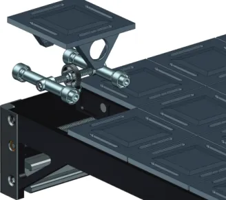
The mechanics of each element is based on two rollers, driven by a worm gear, approaching or departing each other. The rollers create a height change of a surface with a tilted sub-construction, as shown in Figure 2.
Figure 2: Height changing mechanism (low position
(left), high position (right)) consisting of two movable rollers driven by worm gear.
2.2 Mechanics
For proof of concept a first demonstrator was realized. The demonstrator consists of an array of 5x5 single height changing elements, mounted within a mechanical support structure made of plastics using conventional milling. A schematic sketch is shown in Figure 3. Besides the mounting or the elements the support structure encloses a roller guided linear stage, positioning a rack with 5 elec-tric motors below the height-changing elements on de-mand.
Figure 3: Schematic drawing of the single height
chang-ing element within a mechanical support structure. The mechanics of each element, including the gearing, is generated by rapid prototyping using an Eden 250™ 3D
Biomed Tech 2012; 57 (Suppl. 1) © 2012 by Walter de Gruyter · Berlin · Boston. DOI 10.1515/bmt-2012-4172
Printing System (Objet) to process a photopolymer (Full-Cure®850 VeroGray from Objet).
The gearing is designed in a self-blocking way; therefore only when changing the height an external power source is required.
For detecting the applied load on each element a force sensing resistor from interlink electronics (FSR406) is integrated below a force distributing plate. This is located at the top of the element.
2.3 Active load control
As feedback loop for an active load control the data of the sensors are used. The data of each sensor are transferred to a mobile computer and monitored, stored and evaluat-ed. Various approaches to control the height are currently under investigation. Based on the up-to-date and preced-ing data of the elements, includpreced-ing neighbored elements, the OR-personnel will receive a recommendation to shift the height of single or multiple elements if a recommend-ed threshold value is excerecommend-edrecommend-ed. If acceptrecommend-ed, the linear stage will be position the driving motors below the in-volved elements an lever them, until the applied load is decreasing below a second predefined threshold value. As a matter of fact the applied load relies on the patient. Therefore the patient has to be considered within design of the control.
Figure 4: A demonstrator for a 5x5 module with 25
height-changing elements.
For experimental investigation on the behavior of control a set-up using a spring-mass combination was realized. Using this setup, a simulation of reducing load while low-ering an element can be realized for a single height-changing element.
3
Results
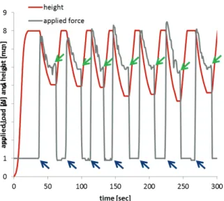
In a first step a particular focus was set on the design of control for a single element. Neglecting the preceding his-tory of applied load, the response of a single element (red) due to an applied load (grey) exceeding the predefined threshold is shown in Figure 5. As the load is increased above the threshold (6 N), the system starts to lower the
height immediately until a lower threshold (4 N) is reached.
Figure 5: Response of the height-changing element (red)
due an increased applied load (grey) without an evalua-tion of load history.
A repetitive application (indicated by blue arrow) and re-moval (indicated by green arrows) of a load is shown in Figure 6. As soon as the load is exceeding the threshold value the height changing element is lowered until the ap-plied force drops below a second threshold value.
Figure 6: Repetitive application (blue arrows) and removal
(green arrows) of load (grey) resulting in an immediate change of height (red) of the element.
Concerning the 5x5 module a particular focus was set on the basic mechanics. A height change at a speed of ap-proximately 2cm/min results in a full shift of height (2 cm) within a minute. This leads to duration slightly above 10 minutes, to shift all 25 elements within the full shift of height. For an operational device a higher stiffness of the supporting frame is required.
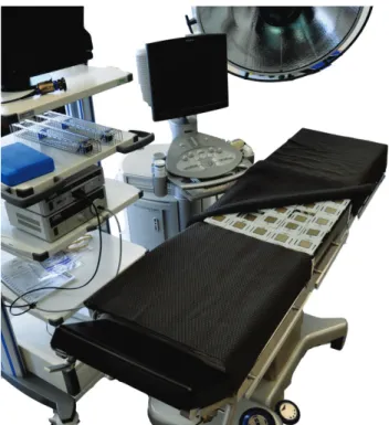
A demonstrator, proofing the feasibility of the linear stage concept was established and integrated within a commer-cial OR-table in our demo lab (Figure 7).
Biomed Tech 2012; 57 (Suppl. 1) © 2012 by Walter de Gruyter · Berlin · Boston. DOI 10.1515/bmt-2012-4172
Figure 7: Integration of a 5x5 module within an OR-table
(OR demo lab).
4
Conclusion
Within this feasibility study, we set up an active bedding module, as a demonstrator for a decubitus prophylaxes during surgical procedures.
As the current demonstrator is manufactured not in the way intended, the mechanical properties do not meet the requirements yet. Anyway the basic concept could be ver-ified successfully and further work packages could be identified.
Up-to-date there is no final decision concerning the ele-ments footprint made. This topic has to be covered in more detail, requiring a complete active bedding system. Up to now only single elements were evaluated. Extend-ing the control towards multiple elements, new strategies of control are arising. For elaborating and testing these strategies this demonstrator offers promising experimental set-up.
Creating this demonstrator the proof of concept of the chosen approach was successfully verified and enables the authors to succeed with the development of an active load controlled bedding system.
5
Acknowledgement
We would like to thank Commission for Technology and Innovation CTI of the Federal Department of Economic Affairs (Switzerland) for financial support.
6
References
[1] EPUAP, Prevention and treatment of pressure
ulcers: quick reference guide.: European Pressure
Ulcer Advisory Panel and National Pressure Ulcer Advisory Panel, 2009.
[2] J. B. Reswick and J. E. Rogers, "Experience at Rancho Los Amigos Hospital with devices and techniques to prevent pressure sores," in Bed Sores
Biomechanics, R. M. Kenedi, et al., Eds., ed
London: University Park Press, 1976, pp. 301-310. [3] N. P. Graves, et al., "Effect of Pressure Ulcers on
Length of Hospital Stay," Infection Control and
Hospital Epidemiology, vol. 26, pp. 293-297, 2005.
[4] C. Leffmann, et al., "Dekubitus," Robert Koch-Institut Berlin 2002.
[5] G. Bennett, et al., "The cost of pressure ulcers in the UK," Age and Ageing, vol. 33, pp. 230-235, May 1, 2004 2004.
[6] S. Baron, "Reducing pressure ulcer risk in the operating room," ed: Allen Medcial Systems, 2009. [7] K. Beckrich and S. A. Aronovitch,
"Hospital-acquired pressure ulcers: A comparison of costs in medical vs. surgical patients," Nursing Economic$, vol. 17, p. 263, 1999.
[8] J. H. Silverstein, et al., Geriatric Anesthesiology, 2nd ed.: Springer New York, 2007.
[9] M. Clark and J. Andrews, "Comparison of Interface Pressures Measured at the Sacrum while Resting upon Two Types of Foam Mattresses and between Platilon and Plastic Mattress Covers," Age and
Ageing, vol. 20, pp. 267-270, July 1, 1991 1991.
[10] C. Tebel and B. Karsunke, "Messung von Drücken auf der Haut während chirurgischer Eingriffe," ed. Puchheim, Saalfeld: unveröffentlichte Studie der Trumpf Medizin Systeme GmbH, 2009.
Biomed Tech 2012; 57 (Suppl. 1) © 2012 by Walter de Gruyter · Berlin · Boston. DOI 10.1515/bmt-2012-4172