Publisher’s version / Version de l'éditeur:
Coastal Structures 2011 : Proceedings of the 6th International Conference, pp.
599-610, 2013-01-01
READ THESE TERMS AND CONDITIONS CAREFULLY BEFORE USING THIS WEBSITE. https://nrc-publications.canada.ca/eng/copyright
Vous avez des questions? Nous pouvons vous aider. Pour communiquer directement avec un auteur, consultez la première page de la revue dans laquelle son article a été publié afin de trouver ses coordonnées. Si vous n’arrivez pas à les repérer, communiquez avec nous à PublicationsArchive-ArchivesPublications@nrc-cnrc.gc.ca.
Questions? Contact the NRC Publications Archive team at
PublicationsArchive-ArchivesPublications@nrc-cnrc.gc.ca. If you wish to email the authors directly, please see the first page of the publication for their contact information.
Archives des publications du CNRC
This publication could be one of several versions: author’s original, accepted manuscript or the publisher’s version. / La version de cette publication peut être l’une des suivantes : la version prépublication de l’auteur, la version acceptée du manuscrit ou la version de l’éditeur.
For the publisher’s version, please access the DOI link below./ Pour consulter la version de l’éditeur, utilisez le lien DOI ci-dessous.
https://doi.org/10.1142/9789814412216_0052
Access and use of this website and the material on it are subject to the Terms and Conditions set forth at
Laboratory investigation of breakwater crown wall comprised of
permeable rock cages
Baker, Scott; Cornett, Andrew; Mahlujy, Keyvan
https://publications-cnrc.canada.ca/fra/droits
L’accès à ce site Web et l’utilisation de son contenu sont assujettis aux conditions présentées dans le site LISEZ CES CONDITIONS ATTENTIVEMENT AVANT D’UTILISER CE SITE WEB.
NRC Publications Record / Notice d'Archives des publications de CNRC:
https://nrc-publications.canada.ca/eng/view/object/?id=0dd6c45c-8ea6-4b2e-89d3-c24e78134545 https://publications-cnrc.canada.ca/fra/voir/objet/?id=0dd6c45c-8ea6-4b2e-89d3-c24e78134545COMPRISED OF PERMEABLE ROCK CAGES Scott Baker1, Andrew Cornett2, and Keyvan Mahlujy3
In this paper we explore the use of large permeable rock-filled cages as an innovative, economical and effective means of reducing overtopping on a large rubble-mound breakwater exposed to energetic breaking waves. The results of a physical modelling study demonstrate that significant reductions in wave overtopping can be achieved by erecting crown walls comprised of permeable rock-filled cages. The testing program included several different arrangements of rock cages and also included a sensitivity analysis with regards to rock cage permeability and interlocking friction.
INTRODUCTION
Coastal engineers are constantly searching for new ways to optimize the design of rubble-mound breakwaters to improve stability, performance and constructability while also minimizing costs. For many breakwaters, overtopping rates must be minimized in order to protect valuable infrastructure located behind the crest, such as vessels, roadways and material handling equipment. Ensuring that rates of wave overtopping remain below acceptable levels in all conditions is an important aspect of performance in many situations.
In general, overtopping rates can be reduced in many ways, for example: by raising the crest elevation, increasing the crest width, constructing a horizontal bench below the crest, and by increasing the permeability and/or roughness of the armour layer and underlayers. However, all these methods tend to drive up costs. Concrete crown walls in various sizes and with various profiles can be used to reduce overtopping, but in many situations these can be relatively expensive to fabricate and install.
Many researchers, including Ingram et al. (2008), Martin et al. (1999), Monso et al. (1997) and Wijetunge (2007), have studied the stability and effectiveness of concrete crown walls. Hamilton & Hall (1993) carried out a series of 2D hydraulic model studies to investigate the stability of rubble-mound breakwater crown walls. The crown wall superstructure was located on the crest of a conventional multi-layer breakwater. Pedersen & Burcharth (1993) studied both the wave forces imposed on the breakwater crown wall and the performance of the structure in reducing wave overtopping. However, we are unaware of previous research considering the use of permeable rock-filled cages to construct crown walls on rubble mound breakwaters.
In this paper, we explore the use of large permeable rock-filled cages as an innovative, economical and effective means of reducing overtopping on a large
1
NRC Canadian Hydraulics Centre, Ottawa, Canada. scott.baker@nrc-cnrc.gc.ca
2
NRC Canadian Hydraulics Centre, Ottawa, Canada. andrew.cornett@nrc-cnrc.gc.ca
3
rubble-mound breakwater exposed to energetic breaking waves. This research was conducted as part of a larger 2D hydraulic modelling study which also explored the measurement of wave overtopping forces, the variation in overtopping force behind the crest, and Core-Loc stability on a horizontal crest. PROJECT INFORMATION
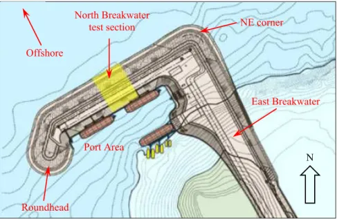
A new port facility is to be constructed in conjunction with the development of a large iron-ore deposit located nearby. The proposed development includes a new breakwater that incorporates a sheltered berthing area for tugs and several berths with loading facilities for feeder ships. The main parts of the port facility are named in Figure 1. Wave conditions at the site are generally quite mild, but can become severe at times due to the effects of tropical cyclones moving through the area. The cyclones can also generate large storm surges. The seabed elevation at the base of the breakwater is approximately -12 m. The maximum surge plus tide elevation at the site is predicted to be 6.1 m above datum. During such an event, the water depth near the edge of the breakwater will be close to 18 m. The northern side of the structure will be exposed to large and highly energetic waves during these storms. Preliminary alternatives for the north breakwater (the focus of this study) consisted of various designs with crest heights varying between +15 m to +20 m. The side exposed to wave attack is to be protected with large Core-Loc concrete armour units, while the sheltered side of the structure facing the port area is to be covered with rock armouring.
A physical modelling study was undertaken to support the design of this new infrastructure. The main objectives for the study were to:
• Reduce the intensity of wave overtopping beyond the crest to reduce forces on topside structures (conveyor, barge loader, etc.);
• Assess the feasibility of using permeable rock-filled cages to form a crown wall as protection against severe overtopping flows;
• Assess the performance of Core-Loc units placed on a flat crest, and establish an acceptable elevation for the crest;
• Assess the performance of armour rock beyond the Core-Loc on the crest and the overall crest width required; and,
• Optimize the proposed designs to improve their performance and constructability, and to reduce their costs.
These objectives were fulfilled by designing and constructing a 1:52.5 scale 2D physical hydraulic model of a short length of the north breakwater, and by conducting tests to investigate the wave–structure interactions and the hydraulic stability of the structure in a range of severe metocean conditions. The investigations were conducted in the Multidirectional Wave Basin test facility at the NRC Canadian Hydraulics Centre (CHC) located in Ottawa, Canada.
A design storm sequence (see Table 1) was developed for testing the breakwater. A single antecedent seastate corresponding to less extreme conditions with a return period of approximately 15 years was used to
“shakedown” the model structure. The structure was then exposed to various combinations of water levels and seastates associated with return periods from 50 to 100 years. Finally, the model structure was exposed to two additional seastates with return periods greater than 100 years, representing overload conditions.
Offshore
North Breakwater
test section NE corner
East Breakwater
Port Area
N
Roundhead
Figure 1. Plan view of the northern section of the port facility.
Table 1. Design wave conditions and water levels for model testing.
Seastate Water Level (m) Hs (m) Tp (s) Duration (hrs)
A1 3.1 4.0 15 3 D1 3.1 5.0 17 4 D2a 3.1 5.5 15 3 D2b 5.1 5.5 15 3 D3 5.1 4.7 11 3 D4 5.1 6.0 13 3 D5 6.1 6.0 15 3 D6 6.1 6.0 18 4 O1 6.1 5.6 11 3 O2 7.1 6.9 18 4 PHYSICAL MODELLING
The model tests were conducted in CHC’s 36 m by 30 m Multidirectional Wave Basin, a state-of-the-art facility for engineering research and testing of maritime structures in the ocean environment. The physical model layout was designed and constructed to evaluate the performance of a small portion of the north breakwater under normally incident waves. A 30 m long segmented wave generator located along the side of the basin was used to generate a wide range
of long-crested wave conditions in the model. The model studies were conducted at a geometric scale of 1:52.5. Froude scaling laws were used to convert quantities measured in the model to full scale values. Freshwater was used in this study to represent seawater. The rock materials and armour units on the surface of the structure were sized to have the same hydraulic stability as in nature, including the effects of the different water densities in the model and nature.
Model Construction
The bathymetry directly offshore of the future port facility is relatively flat and level at a depth of approximately -12 m. For this reason, it was decided that the breakwater model could be constructed on a level floor. In the model, the level bathymetry area was preceded by a mild slope leading down to the wave generator, which was located near the -23 m depth contour. Unidirectional (long-crested) irregular waves were used in this study. To increase the spatial uniformity of these waves, 20 m long solid vertical walls were installed extending from both ends of the 30 m long wave generator to prevent diffraction and to retain all the wave energy until the waves reached the absorbing beaches. Additional wave absorbers were also installed opposite to the wave generator in order to minimize wave reflections.
After the model was equipped with wave gauges, the incident wave conditions to be used in the study were calibrated and verified to ensure conformity with design values. For all seastates, the variance of Hs was less than
1% from the target significant wave height.
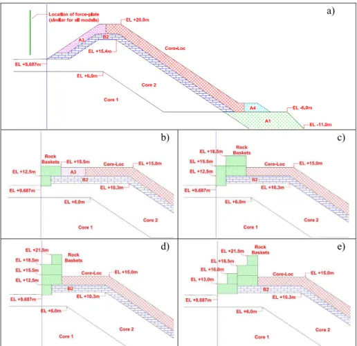
Once the wave calibrations were completed, scaled replicas of various alternative breakwater cross-sections (two at a time) were constructed in the model using rock materials and armour units selected to replicate the hydraulic stability of the prototype materials. The test sections were located near the centre of the 30 m wide basin. Each test section was 1.5 m wide in the model and represented ~79 m length of the breakwater trunk at full scale. Two sturdy walls were used to define the outer edges of the cross-sections. A transparent sheet of Plexiglass was used to separate the two different cross-sections from each other. The model layout is shown in Figure 2. The Base Case alternative is a conventional breakwater design with a tall crest armoured with Core-Loc, seen in Figure 3a.
Due to an insufficient supply of model Core-Loc units, larger model Accropode units were used in dummy sections that were not considered as part of the testing cross-section. In the dummy sections (near the solid walls), the thickness of the filter layer was suitably reduced such that the surface of the larger Accropode units would remain flush with the surface of the Core-Loc slope. Approximately 925 scaled Core-Loc units were employed in this study.
Working from CAD cross-section drawings, accurate fibre-board templates were constructed to define the outline of the core and underlayer materials. The
templates were erected on shims that were levelled using precise surveying equipment. The core material was then placed and compacted to match the profile at each template. The crest elevation of the core was also checked by surveying. The filter materials were then bulk placed and lightly packed to match the profile at each template. The templates were removed once the filter materials were placed and verified. The underlayer was painted before continuing. Armour stone material was generally bulk placed and packed to approximate specified profiles, then touched up by hand to carefully match the proposed design. The exposed surface of the armour stone was painted to facilitate the visual assessment of damage.
Figure 2. Plan view of the model in the Multidirectional Wave Basin.
The concrete armour units were placed individually by hand according to the methods specified by Concrete Layer Innovations (CLI). Templates were prepared to guide the horizontal and vertical spacing of each unit. The units were placed individually by hand in specific locations but with pseudo-random orientations. The placement was inspected prior to testing to verify good agreement with specifications. This study utilized the performance criteria recommended by CLI to assess the stability of Core-Loc units in physical model studies.
One of the initial design alternatives included a modest 6 m high crown wall comprised of large rectangular wire cages (6 m by 3 m by 3 m at full scale) filled with rock. The model cages were designed with a mesh size approximately half the size of the smallest rock material that was used to fill them. Forty individual cages were constructed before the testing program began.
Figure 3. Comparison of selected design alternatives for the breakwater trunk (see Table 2 for descriptions).
Based on the encouraging performance of this particular design alternative, and a desire to minimize overtopping without increasing the overall cost of the breakwater, nine different design sections with crown walls comprised of rock cages were subsequently studied in the physical model. Several of the designs featured crown walls comprised of numerous rock cages that extended as much as 11.2 m above the crest of the core material (see Figure 3d and 3e).
a)
b) c)
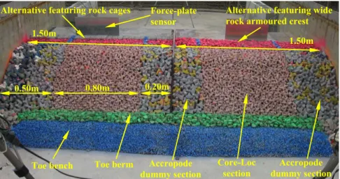
In some cases, the cages were arranged in various ways in order to improve the overall stability of the crown wall. Several larger rock cages (the size of 6 cages side-by-side) were constructed in order to test some of these alternate configurations. Throughout the testing program, wooden shims were used at the outer edges of the cross-section to prevent the rock cages from being wedged too tightly together which might provide them with unrealistic interlocking capabilities. After installation, each unit was physically checked to ensure that it was free to move relative to its neighbours. Figure 4 depicts an overview of the model structures before testing.
Figure 4. Overview of the two model test-sections.
Instrumentation
Nine capacitance wave gauges were deployed to measure wave conditions at various locations throughout the model domain. The measured wave records were analyzed using comprehensive and well-proven analysis procedures. Numerous statistics and derived parameters were computed from the time histories recorded at each gauge.
Instead of measuring overtopping discharge, two force-plate sensors (shown in Figure 4) were developed and used to measure the hydrodynamic forcing exerted by the overtopping flow on a vertical wall at various locations on and behind the crest of the breakwater. Each force-plate consisted of a rectangular aluminum plate connected by 3 stiff rods to 3 high-precision shear beam load cells, which were mounted to a sturdy base. Each aluminum plate was 250 mm tall by 500 mm wide in model scale, representing approximately 13 m by 26 m at full scale. The force-plates were sampled at a rate of 500 Hz (model scale). Each load cell was calibrated prior to assembly. Once constructed, the force-plates were checked in situ by applying a time-varying load through a reference
Toe bench Toe berm Accropode
dummy section Accropode dummy section Core-Loc section 1.50m 1.50m
Alternative featuring rock cages Force-plate
sensor
Alternative featuring wide rock armoured crest
0.20m 0.80m
load cell to verify the accuracy and set-up. The plates were able to measure the applied force with an accuracy of approximately 2%.
A photographic damage analysis system comprising three remotely-operated digital cameras was used to monitor the movement of the Core-Loc, armour stone, and rock cages used in this study. Since each camera remained fixed throughout the testing, the movement of individual elements could be detected by comparing photographs taken at different times. The visual detection of movement was enhanced by carefully overlaying two images and rapidly alternating which of the two images was visible.
RESULTS AND OBSERVATIONS Measuring overtopping force
Overtopping flows are normally measured and assessed in terms of a time-averaged flow rate. While this approach can be helpful when establishing requirements for drainage, the impacts of the overtopping flows on infrastructure and equipment located on or behind the breakwater crest remains unknown. For this reason, the forcing due to the overtopping flows was measured in this study, rather than the overtopping discharge.
The force-plates employed in this study provided an excellent means of quantifying and understanding the hydrodynamic forces due to wave overtopping at the structure’s crest and behind the crown walls, on a wave-by-wave basis. The high-precision load cells were able to capture the smallest of forces from splash and spray behind the crown wall, right up to the maximum forcing generated by green-water impact seaward of the crown wall. A peak detection algorithm was applied to the force-time history to detect the local maxima in each record. Numerous statistics and derived parameters were also computed.
Unfortunately, the force measurements could not be reliably converted to pressures due to the large size of the plates and the spatial variability of the loading across each plate at any instant. Pressures could be more reliably determined by using smaller force-plates. However, due to the randomness of the overtopping, the peak overtopping forces could easily be missed by a smaller instrument. Nevertheless, the force measurements obtained in this study were helpful in assessing the risks to sensitive infrastructure and equipment located behind the breakwater crest due to the overtopping flows. This approach also proved to be an effective and reliable method of measuring and comparing the relative performance of the various crown wall designs that were investigated in this study.
In addition to collecting overtopping force measurements at one critical location behind the breakwater crest, additional tests were performed to determine the variation in overtopping force with respect to horizontal distance behind the crest in order to develop a force-decay curve. In this case, “behind the crest” is defined as the point where the backside slope of the crest meets
with the level working surface area located lee-ward (shown as the vertical blue lines in Figure 3). Measurements were performed with offsets of 5.0, 14.5 and 23.9 m (prototype scale) behind the crest. An additional measurement was taken with the force-plate located at the front side crest atop the Core-Loc on a flat crest. This measurement location corresponds to 15.3 m (prototype scale) in front of the defining point behind the crest. The results from this analysis indicated a linear decrease in peak horizontal force was observed with increasing crest offset.
Use of rock cages to reduce overtopping
From a structural perspective, the results of the study demonstrated that crown walls formed by stacking large rock cages are capable of not only surviving extreme overload conditions but also providing a significant reduction in overtopping flows. A number of different rock cage configurations were investigated during this study and many of these configurations were very stable, even during overload conditions. However, as the wall of cages became higher in order to further decrease the overtopping, the integrity and stability of the structure decreased. It was determined that using a “stepped” configuration of rock cages, as shown in Figure 3e, was the most structurally sound, while offering the greatest reduction in overtopping. The importance of recessing the bottom row of cages into the filter materials was also clearly demonstrated in these tests. Table 2 describes the overall performance of several selected design alternatives. All of these alternatives are sketched in Figure 3. The design sketched in Figure 3e remained stable and provided excellent protection against overtopping, even during severe overload conditions. For the design section sketched in Figure 3e, the maximum force exerted by the overtopping flows in the design storm was just 2% of the forcing for the Base Case design, sketched in Figure 3a.
Table 2. Comparison of overtopping and stability for selected design alternatives.
Design Alternative Maximum overtopping force
(% relative to Base Case) Stability performance rating Base Case (Fig. 3a) 100% Moderate damage, allows notable
overtopping flows Single layer rock cage crown wall
with 21.6 m wide crest (Fig. 3b) 100%
Rock cages stable, allows significant overtopping flows Two layer rock cage crown wall with
14.3 m wide crest (Fig. 3c) 21%
Rock cages moderately stable, notable reduction in overtopping flows Three layer rock cage crown wall with
14.3 m wide crest (Fig. 3d) 6%
Rock cages unstable, significant reduction in overtopping flows Stepped three layer rock cage crown
wall with 14.3 m wide crest (Fig. 3e) 2%
Rock cages stable, significant reduction in overtopping flows
Sensitivity to rock cage permeability
Following the excellent performance of one of the initial rock cage layouts, sensitivity tests were conducted to assess, in a qualitative manner, the influence
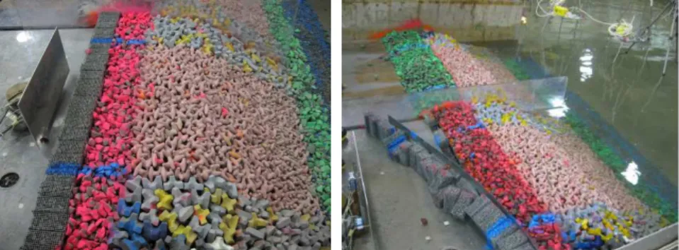
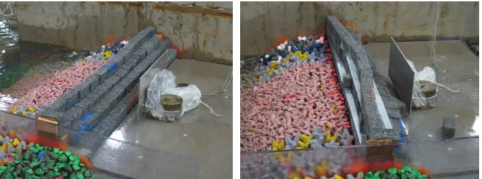
of changes in the horizontal permeability of the cages. Impermeable metal sheets were installed in front of the rock cages in order to simulate the situation where the porous cages were replaced by a rock filled rectangular prism that did not have any perforations on its seaward face (such as a shipping container).
After testing this alternative, it was clearly observed that the solid metal sheet on the seaward side of the cages prevented the overtopping flows from seeping into and dissipating within the rock cages. The hydrodynamic forcing on the impermeable rock cages was clearly larger than on the permeable cages. In one overload test condition, the forcing was sufficient to displace many of the cages a considerable distance from their initial locations, which caused the crown wall to fail. Open permeable rock cages were shown to be more stable than closed impermeable ones. Figure 5 shows a comparison of the performance of the two options (impermeable versus permeable cages) following exposure to the same overload event.
Figure 5. Demonstration of the influence of rock cage permeability: a) permeable; b) impermeable.
Sensitivity to rock cage friction
Following the superior performance of one of the final rock cage layouts, it was desired to investigate what effect, if any, the friction between individual rock cage units had on the overall stability of the barrier. In order to examine this, thin metal sheets were placed between each vertical layer of rock cages. Smaller sheets were also inserted vertically between the individual rock cage units within each row. The desired effect of the metal sheets was to reduce the friction between adjacent rock cages; however, the magnitude of the reduction was not measured. Metal sheets were not inserted below the rock cages in the bottom rows, as these units rested directly on the core or filter material below them.
The resulting tests demonstrated clearly that the inter-cage friction plays an important role. The crown wall with the metal sheets was clearly less stable than the comparable barrier without metal sheets. Many rock cages were displaced farther than previously observed, and several rock cages were pushed completely off the crest onto the level working area. Figure 6 shows a
comparison of the performance of the two options (regular friction versus reduced friction) following exposure to the same overload event.
Figure 6. Demonstration of the influence of inter-cage friction: a) regular friction; b) reduced friction.
Core-Loc stability on a horizontal crest section
Core-Loc placement on the front slope was performed as per CLI standards. At the wide horizontal crest, the placement technique was modified to follow the recommended arcing/semi-circle procedure. On the crest, Core-Loc placement started from the back (at the interface with the rock cages) in order to have proper contact of the back row. Units were then placed towards the last row of the slope in a more-or-less semi-circular fashion.
During testing, the Core-Loc on both the slope and the crest performed well, even after repeated exposure to overload wave conditions. In order to prevent any rocking of the last row of units abutting the rock cages, a few armour stones were placed in the small gaps between the units and the rock cages. This chinking appeared to increase the stability of the Core-Loc units.
CONCLUDING REMARKS
The results of this study show that permeable rock-filled cages can be stacked to form effective barriers on top of coastal structures, and that this approach can be more cost effective than other design options, such as raising the structure’s core, or erecting a concrete crown-wall. For a given cross-section and metocean conditions, the stability of a rock cage barrier is dependent on several factors, including:
• the pattern in which the cages are stacked and the degree of interlocking between them;
• whether the bottom row of cages are recessed into the filter and core materials;
• the permeability of the cages; and, • the friction between the cages.
While these influences have been investigated qualitatively in this study, further research to quantify the influence of these factors is encouraged.
Measuring the forces exerted on a vertical wall located behind the crest of a coastal structure is a simple and effective means to quantify the relative severity of the overtopping flows on a wave by wave basis. The reduction in wave overtopping depends primarily on the overall height and width of the barrier, and on the permeability of the rock-filled cages. The overtopping is lower for barriers that are higher, wider and comprised of cages with low permeability. The horizontal forcing due to the overtopping flows also decreases significantly with increasing horizontal distance behind the crest. Further research to develop relationships between the forcing and the flow rate is encouraged.
Some consideration has been given to the practicality and constructability of these rock cages. Ideally, the cages would be constructed on-site and installed using either land or sea-based cranes. The cages could be constructed out of large sections of pre-assembled wire mesh sheets, which could then be folded into shape, filled with rock, and joined with neighbouring cages. The bottom of the cage could be left open to maximize inter-locking friction between stacked units as well as the core/underlayer. To prevent corrosion issues and to prolong the design life of the structure, galvanized steel mesh could be used; otherwise an allowance for steel corrosion should be considered in the design.
Significant reductions in wave overtopping at rubble-mound coastal structures can be achieved by erecting crown walls comprised of interlocked arrangements of permeable filled cages. Crown walls comprised of rock-filled cages with low permeability are effective at minimizing overtopping flows, but are less stable than walls comprised of permeable cages. The friction that develops between the individual cages is another important factor contributing to the overall stability of the crown wall. Crown walls comprising permeable rock-filled cages could be the most economical approach in many situations, and are therefore well worth considered in design. The promising results obtained in this initial study suggest that further research on this topic would be worthwhile.
REFERENCES
Hamilton, D.G., Hall, K.R., 1993. Preliminary analysis of the stability of rubble mound breakwater crown walls. Proc. 23rd Int. Conf. Coastal Eng., ASCE, 1217-1230.
Ingram, D., Bruce, T., Allsop, W., 2008. Post-Overtopping Loads Behind Vertical Structures. Proc.
31st Int. Conf. Coastal Eng., World Scientific Publishing, 3144-3156.
Martin, F.L., Losada, M.A., Medina, R., 1999. Wave loads on rubble mound breakwater crown walls. Coastal Engineering 37:149-174.
Monso, J.L., Vidaor, A., Cadevall, C., Garcia, C., 1997. Overtopping reduction in crown wall design.
Proc. 25th Int. Conf. Coastal Eng., ASCE, 1816-1825.
Pedersen, J., Burcharth, H.F., 1993. Wave forces on crown walls. Proc. 23rd Int. Conf. Coastal Eng.,
ASCE, 1489-1502.
Wijetunge, J.J., 2007. Large-scale wave run-up and overtopping measurements over a straight rubble-mound breakwater without a crown wall. Proc. 5th Int. Conf. Coastal Structures., World
P0201
LABORATORY INVESTIGATION OF BREAKWATER CROWN WALLS COMPRISED OF PERMEABLE ROCK CAGES
Baker, Scott Cornett, Andrew Mahlujy, Keyvan Breakwaters Crown walls Coastal structures Model testing Overtopping Rock cages