Publisher’s version / Version de l'éditeur:
Vous avez des questions? Nous pouvons vous aider. Pour communiquer directement avec un auteur, consultez la première page de la revue dans laquelle son article a été publié afin de trouver ses coordonnées. Si vous n’arrivez pas à les repérer, communiquez avec nous à PublicationsArchive-ArchivesPublications@nrc-cnrc.gc.ca.
Questions? Contact the NRC Publications Archive team at
PublicationsArchive-ArchivesPublications@nrc-cnrc.gc.ca. If you wish to email the authors directly, please see the first page of the publication for their contact information.
https://publications-cnrc.canada.ca/fra/droits
L’accès à ce site Web et l’utilisation de son contenu sont assujettis aux conditions présentées dans le site LISEZ CES CONDITIONS ATTENTIVEMENT AVANT D’UTILISER CE SITE WEB.
2011 CSCE Annual Conference: 14 June 2011, Ottawa, Canada [Proceedings],
pp. 1-10, 2011-06-14
READ THESE TERMS AND CONDITIONS CAREFULLY BEFORE USING THIS WEBSITE. https://nrc-publications.canada.ca/eng/copyright
NRC Publications Archive Record / Notice des Archives des publications du CNRC : https://nrc-publications.canada.ca/eng/view/object/?id=60a02c76-f5d7-4b95-b816-c132e9f261b7 https://publications-cnrc.canada.ca/fra/voir/objet/?id=60a02c76-f5d7-4b95-b816-c132e9f261b7
NRC Publications Archive
Archives des publications du CNRC
This publication could be one of several versions: author’s original, accepted manuscript or the publisher’s version. / La version de cette publication peut être l’une des suivantes : la version prépublication de l’auteur, la version acceptée du manuscrit ou la version de l’éditeur.
Access and use of this website and the material on it are subject to the Terms and Conditions set forth at
Early-age cracking of steel and GFRP-reinforced concrete bridge
barriers
http://www.nrc-cnrc.gc.ca/irc
Ea rly-a ge c ra c k ing of st e e l a nd GFRP-re inforc e d c onc re t e bridge
ba rrie rs
N R C C - 5 4 4 4 2
C l a u d e , J - F . ; A h m e d , E . ; C u s s o n , D . ;
B e n m o k r a n e , B .
J u n e 2 0 1 1
A version of this document is published in / Une version de ce document se trouve dans:
2011 CSCE Annual Conference, Ottawa, Canada, June 14-17, 2011, pp. 1-10
The material in this document is covered by the provisions of the Copyright Act, by Canadian laws, policies, regulations and international agreements. Such provisions serve to identify the information source and, in specific instances, to prohibit reproduction of materials without
written permission. For more information visit http://laws.justice.gc.ca/en/showtdm/cs/C-42
Les renseignements dans ce document sont protégés par la Loi sur le droit d'auteur, par les lois, les politiques et les règlements du Canada et des accords internationaux. Ces dispositions permettent d'identifier la source de l'information et, dans certains cas, d'interdire la copie de
Early-Age Cracking of Steel- and GFRP-Reinforced Concrete Bridge
Barriers
Jean-François Claude
1, Ehab Ahmed
1, Daniel Cusson
2, and Brahim Benmokrane
11
Department of Civil Engineering, University of Sherbrooke, Quebec, Canada.
2
Institute for Research in Construction, NRC, Ottawa, Ontario, Canada.
Abstract: This paper presents the preliminary results of an experimental study to investigate the
shrinkage and cracking behaviour of GFRP- and steel-reinforced concrete barriers subjected to real environmental and load conditions. This study was conducted through a collaboration project between the University of Sherbrooke and Ministry of Transportation of Quebec (MTQ). The main objective of this investigation was to evaluate the restrained shrinkage cracking behaviour of median barriers (Type MTQ 202ME) reinforced with GFRP and galvanized steel bars and fabricated using high-performance concrete (Type MTQ XIII) with a compressive strength of 50 MPa after 28 days. The barrier under investigation was incorporated in a new Highway 410 Overpass Bridge, located in Sherbrooke, Quebec, which was cast in June 2010. The barrier included one section reinforced with GFRP bars while the second section was reinforced with galvanized steel bars, which, in turn, was divided into two sub-sections with different amounts of longitudinal reinforcement (8 bars and 12 bars). The barrier was instrumented with a set of sensors, including: fibre-optic strain sensors, vibrating wire strain gauges, electrical resistance strain gauges, and thermocouples to capture the strain and temperature evolutions along the barrier length. The behaviour of the barrier for the first few months is presented and discussed in this paper.
1. Introduction
In North America, the deterioration of concrete structures due to the corrosion of steel reinforcement is one of the challenging issues that face the construction industry. Reinforced concrete bridges are among those structures that suffer from corrosion and related deteriorations. This problem is exacerbated when large amounts of de-icing salts are used on bridges during the winter season. Whereas there is a multitude of methods to protect the steel reinforcement from corrosion, such as epoxy coating or galvanizing, the use of non-corrodible fibre-reinforced polymer (FRP) materials can eliminate it.
Reinforced concrete bridge barriers normally exhibit transverse shrinkage cracking which depends on the concrete type and the surrounding environmental conditions as well as the reinforcement type and ratio. These cracks work as localised corrosion initiators. Thereafter, the corrosion of the steel bars leads to sequential deteriorations such as the spalling of the concrete cover and the loss of functionality of the structural element. Thus, replacing the steel reinforcement with non-corrodible GFRP bars will eliminate the potential of corrosion and increase the predicted service live of the reinforced concrete (RC) barriers. However, due to the difference in the mechanical properties and bond characteristics between the GFRP and steel bars, the behaviour of GFRP-reinforced concrete barriers has to be investigated.
Since the lateral impact load is the main component that has to be resisted by a bridge barrier, many studies have been conducted to investigate the structural performance of GFRP-reinforced concrete barriers under static and impact loading. Sennah et al. (2010) reported that both the longitudinal and vertical loads may not be considered in determining the design load of barrier wall reinforcement and anchorages between the deck slab and the barrier wall or the curb because transverse loading governs the determination of the critical load carrying capacity. El-Salakawy et al. (2003) evaluated the experimental response of concrete bridge barriers reinforced with GFRP bars under static and pendulum impact loading. In this study, the GFRP-reinforced concrete sections were designed to achieve the equivalent strength of their steel-reinforced counterparts. The test results showed similar behaviour at failure of both sets (GFRP and steel-reinforced). Based on these results, the MTQ approved the former solution for application in bridges. Thereafter, two concrete bridges were constructed using bridge decks and barriers totally reinforced with GFRP bars. Those two bridges are located in the municipalities of Val-Alain and Melbourne, in Quebec. The former was constructed in 2004 on Highway 20 whereas the latter was constructed in 2005 on Highway 55. In those two bridges, GFRP-reinforced barriers of Types PL-2 and PL-3 were built, respectively (Benmokrane et al. 2007a; 2007b). Later, another investigation was conducted to develop and implement a steel-free concrete deck and railing system (Matta and Nanni 2009). Through a collaborative project between University of Sherbrooke and Ministry of Transportation of Quebec, an experimental study was conducted to evaluate and compare the behaviour of the GFRP-reinforced concrete barriers of Types MTQ 210 and 311 to the behaviour of steel-GFRP-reinforced counterparts under static and impact loads (Benmokrane et al. 2009; Ahmed et al. 2011). It was concluded that the behaviour of the GFRP-reinforced prototype was comparable to that reinforced with steel.
On the other hand, no research work was conducted to investigate the shrinkage and cracking behaviour of GFRP-reinforced concrete barriers subjected to real environmental conditions. Cusson and Repette (2000) presented the early-age cracking of the rehabilitated steel-reinforced concrete barrier walls of the Vachon Bridge in Laval, Quebec. The barrier walls exhibited intense transverse cracking only a few days after concreting due to steep temperature gradients through the barrier wall combined with autogenous shrinkage. Through this investigation, it was concluded that the potential increase in durability of high-performance concrete may be of significant interest in reinforced concrete bridges, especially in areas where de-icing salt is used but appropriate construction techniques have to be employed. It was also pointed out that the early-age transverse cracking due to excessive thermal stresses and restrained shrinkage can overshadow the expected superior durability of low-permeability concrete. After a 10-year corrosion study conducted on the same bridge, Cusson and Qian (2009) reported that the severe early-age transverse cracking of the barrier allowed early ingress of chlorides to the reinforcement and resulted in premature localized corrosion at the cracks, with an increase of 30% in the measured corrosion rate. The MTQ is currently using two standard designs for the GFRP and steel-reinforced barriers of Type MTQ 202ME. Both of them have the same transverse reinforcement amount of GFRP or steel bars (15M@300 mm). However, the steel-reinforced barrier (Figure 1. (a)) contains 8 steel bars (15M) as longitudinal reinforcement and the GFRP-reinforced barrier (Figure 1. (b)) contains 14 GFRP bars (No. 15) as longitudinal reinforcement. As the longitudinal reinforcement plays the main role in controlling restrained shrinkage and consequently transverse cracking in the barrier walls, the MTQ aims at investigating the optimum design of the barrier wall and determining the horizontal reinforcement amount that should be provided, which is planned in the collaborative project presented in this paper.
The main objectives of this investigation were: (i) to evaluate the shrinkage and cracking behaviour of median barriers (Type MTQ 202ME) reinforced with GFRP and galvanized steel bars fabricated using high performance concrete (Type MTQ XIII) with a 28-day compressive strength of 50 MPa; and (ii) to evaluate the efficient amount of horizontal reinforcement that is necessary to keep the crack widths under control. This project was conducted into two phases. Phase I includes the construction and monitoring of the median barrier of the Highway 410 overpass bridge, in Sherbrooke, Quebec. The barrier included one section reinforced with GFRP bars while the second section was reinforced with galvanized steel bars. Phase II includes the finite element analysis of the barrier and the conduct of an extended parametric study after calibrating the model against the experimentally measured ones. This paper presents the first phase of this project dealing with the behaviour of the median barrier considering a few months of monitoring, since it was constructed in June 2010.
(a) (b)
Figure 1: Standard designs of barriers of Type MTQ 202ME: (a) Steel-reinforced; (b) GFRP-reinforced
2. Research Significance
Several studies were conducted to evaluate the structural performance of GFRP-reinforced concrete (GFRP-RC) barriers under static and simulated impact loading conditions. However, their long-term shrinkage and cracking behaviour under real environmental and loading conditions is yet to be addressed. This study evaluates the short and long-term shrinkage and cracking behaviour of GFRP-RC barriers implemented in a field project and subjected to field conditions such as wet/dry cycles, freeze/thaw cycles, temperature fluctuations, and traffic loads. The strain and cracking profile as well as their evolution in time was investigated and compared to their counterparts reinforced with steel.
3. Experimental Program
3.1 Description of the Median Barrier
The median barrier considered in this investigation was part of the Hwy 410 overpass bridge going over Boulevard de l’Université in the municipality of Sherbrooke, and was built in June 2010. The six-lane bridge was constructed using typical slab-on-girder structural system with a total length of about 47.0 m. The median barrier was of Type MTQ 202ME. Figure 2 shows the general layout of the bridge (plan view), and the cross-section geometry of the median barrier.
(a) (b)
Median Barrier
GFRP-Reinforced Section Steel Reinforced Sections
Supporting steel beams 46791 46767 46779 24053 22726 830
Figure 2: Layout of the project: (a) Hwy 410 overpass bridge; (b) Median barrier cross-section (Dimensions in mm)
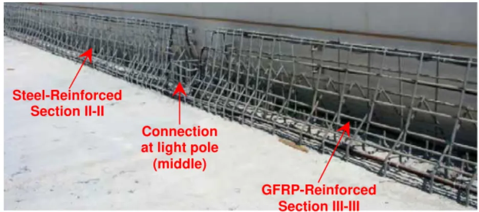
The median barrier has a total length of about 47.0 m. The barrier was divided into two main portions. The first portion was reinforced with GFRP bars No. 15 designated according to CAN/CSA S807-10 (CSA 2010) with a total of 14 GFRP bars No. 15 as longitudinal reinforcement. Figure 3 illustrates the reinforcement details of the median barrier of the Hwy 410 overpass bridge. The second portion was reinforced with galvanized steel bars 15M, which, in turn, was divided into two sub-sections according to the amount of longitudinal bars. The first sub-section was reinforced with a total of 8 galvanized steel bars 15M while the second sub-section was reinforced with a total of 12 galvanized steel bars 15M. It should be mentioned that the GFRP-reinforced portion of barrier was subdivided into 10 small sections (S1 to S10) to facilitate monitoring and crack mapping. The steel-reinforced portion was also subdivided into 10 sections (S11 to S20), including 5 sections (S11 to S15) with 8 longitudinal galvanized steel bars, and 5 sections (S16 to S20) with 12 longitudinal galvanized steel bars (Figure 3). Both of the GFRP-reinforced and steel-reinforced portions of the median barrier were reinforced with the same amount of transverse reinforcement, which was GFRP bars No. 15 @ 300 mm, and galvanised steel bars 15M @ 300 mm, respectively. Figure 4 presents a photograph of the reinforcement configuration of both reinforced sections. It should be mentioned that the concrete cover was equal to 75 mm in steel- and GFRP-reinforced sections. This concrete cover is devoted to protect the steel bars against the infiltration of salts. However, for the GFRP bars, this concrete cover may be reduced.
The formwork was made of plywood panels for both barrier wall sides. The reinforcement configuration of both of the GFRP-reinforced and steel-reinforced sections of the median barrier were prepared and cast in June 2010 using ready-mix high-performance concrete of Type MTQ XIII. The top surface of the barrier wall was covered with wet burlap until the formwork was removed 7 days after concreting. Figure 5 shows the casting of the barrier and a general view of the barrier after the casting and removal of the formwork.
Figure 3: Reinforcement details of the median barrier
Figure 4: Reinforcement configuration of the median barrier at different sections
14 GFRP bars 12 Steel Bars 8 Steel Bars
North S 1 S 2 S 3 S 4 S 5 S 6 S 7 S 8 S 9 S 18 S 19 S 20 S 17 S 16 S 15 S 14 S 13 S 12 S 11 S 10 22726 mm 24053 mm I II III Steel-Reinforced Section II-II GFRP-Reinforced Section III-III Connection at light pole (middle) EM-112-4
(a) During concrete casting (b) After formwork removal Figure 5: Fabrication of the median barrier in June 2010
3.2 Material Properties
Similar to many projects that are being constructed by the MTQ in Quebec, galvanized steel bars were employed in this project for the steel-reinforced structural members of the bridge. For the steel-reinforced section of the median barrier, galvanized steel bars 15M were used as reinforcement. The bars had a cross-sectional area of 200 mm2 and a yield stress of 450 MPa with a corresponding strain of 0.225%.
On the other hand, the GFRP-reinforced section of the median barrier was reinforced with sand-coated GFRP bars No. 15 (15.9-mm diameter) designated according to CAN/CSA S807-10 (CSA 2010). The sand coating of these bars is devoted to enhance the bond between the GFRP bars and the surrounding concrete. The tensile strength and elastic modulus of the bars used in this project were 751 MPa and 48.2 GPa, respectively (Pultrall 2010). Table 1 lists the mechanical properties of the GFRP bars No. 15.
Table 1: Properties of the GFRP bars No. 15 (Pultrall 2010)
Bar size* Effective Area (mm2) Elastic Tensile Modulus, EFRP, (GPa) Ultimate Tensile Strength (MPa) Guaranteed Tensile Strength (MPa) Ultimate tensile Elongation (%) No. 15 199 48.2 751 683 1.56
* Designated according to CAN/CSA S807-10 (2010)
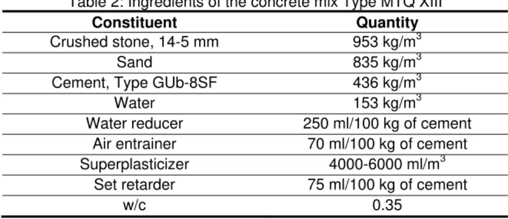
The median barrier was cast using ready-mix high-performance concrete of Type MTQ XIII with an air-entrained content ranging from 5 to 8 %. The 28-day specified compressive strength of this type of concrete is 50 MPa. The concrete contained 436 kg/m3 of CSA Type GUb-8SF Cement and had a water-cement ratio (w/c) of 0.35. The ingredients of the concrete mix are presented in Table 2. The measured compressive strength of the concrete cylinders after 28 days was 62.3 MPa.
Table 2: Ingredients of the concrete mix Type MTQ XIII
Constituent Quantity
Crushed stone, 14-5 mm 953 kg/m3
Sand 835 kg/m3
Cement, Type GUb-8SF 436 kg/m3
Water 153 kg/m3
Water reducer 250 ml/100 kg of cement Air entrainer 70 ml/100 kg of cement
Superplasticizer 4000-6000 ml/m3
Set retarder 75 ml/100 kg of cement
3.4 Instrumentation
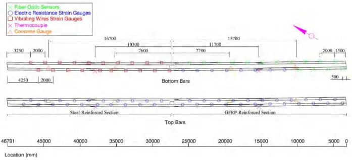
Since the main objective was to investigate and monitor the shrinkage and cracking behaviour of the median barrier of Type MTQ 202ME, a multitude of sensors were selected to capture the strain and temperature variations of the barrier over time. A total of 98 sensors were attached to the reinforcing bars and embedded in concrete. The sensors include 15 fibre-optic strain sensors (FOS) attached to the GFRP reinforcing bars; 20 vibrating wire strain gauges (VWSG) attached to the steel bars; 8 vibrating wire strain gauges (VWSG) embedded in the concrete; 4 thermocouples (TH); and 51 electrical resistance strain gauges (ESG) attached to the GFRP and steel bars. The instrumented bars are identified in Figure 3, while Figure 6 shows the locations of the different sensors that were attached to the top and the bottom reinforcing bars (steel and GFRP).
The FOS, VWSG, and ESG were attached to four longitudinal bars. As illustrated in Figure 3, two bars located at the bottom of the barrier section and two bars at the top were selected to capture the strain variation along the depth of the barrier. The vibrating wire strain gauges for concrete were installed in the concrete at the level of the instrumented longitudinal bars (top and bottom). The thermocouples were installed close to these reinforcing bars to determine the actual temperature surrounding the bars for temperature corrections of the strain data. It is worth mentioning that the vibrating wire strain gauges are equipped to measure temperature in addition to strain.
Regardless of the types of strain sensors used on reinforcing bars, the sensors (FOS, VWSG, ESG) were distributed with a longitudinal spacing of 2.0 m to capture the strain variation along the whole length of the median barrier, and to trace and evaluate the effects of cracking and temperature variation.
Figure 6: Instrumentation details of the median barrier (plan view)
4. Test Results and Discussion
4.1 Crack Mapping and Widths
As soon as the formwork was removed on June 16, 2010 (7 days after casting), the crack pattern and the initial crack widths in the GFRP- and steel-reinforced sections were recorded. The initial maximum crack width recorded in the steel-reinforced sections of the barrier (with either 8 or 12 bars) was 0.15 mm. The initial crack spacing ranged from 406 mm to 1434 mm with an average of 749 mm in the section reinforced with 8 steel bars 15M (S11-S16). However, in the section reinforced with 12 steel bars 15M (S16-S20), the initial crack spacing ranged from 316 mm to 2195 mm with an average of 905 mm. The
GFRP-reinforced section exhibited an initial maximum crack width of 0.18 mm, which is almost the same as that of the steel-reinforced section. The initial crack spacing ranged from 406 mm to 1166 mm with an average of 705 mm, which is also close to the average value measured in the steel-reinforced section. It should be noted that the sudden changes in the barrier geometry and reinforcement detail at the light pole between S10 and S11 resulted in the formation of two additional transverse cracks with larger widths (0.33 mm and 0.34 mm).
The crack propagation over time is shown in Figure 7, while the time evolution of crack width and crack spacing are presented in Figures 8 and 9, respectively. The cracks in both of the GFRP- and steel-reinforced sections developed in the first month after removing the formwork. Since then, only one crack appeared in each of the two sections on October 28, 2010. However, the crack width in both reinforced sections has increased from June 16 to October 28, as clearly shown in Figures 8 and 9. Thereafter, the crack widths followed the seasonal temperature variation and have decreased with decreasing ambient temperature in the winter season.
On the other hand, the crack widths recorded in the steel-reinforced section with 12 steel bars 15M (S16 to S20) were smaller than that of the other section reinforced with 8 steel bars 15M (S11 to S15). This is attributed to the difference in the number of longitudinal reinforcing bars as well as in the boundary conditions. Moreover, after 7 months of monitoring, the GFRP-reinforced section (S1 to S10) showed larger crack widths than those of the steel-reinforced section due to the lower axial stiffness of the GFRP bars in comparison to steel bars.
Starting on October 28, 2010, it can be observed that the crack widths have decreased due to the decreasing temperature. The crack widths are expected to follow the seasonal temperature changes.
June 16, 2010 June 21, 2010
July 07, 2010
Figure 7: Crack mapping of the median barrier (elevation view)
Figure 8: Evolution of average crack width June 18, 2010
14 GFRP bars
12 Steel Bars 8 Steel Bars
North Section 1 Section 2 Section 3 Section 4 Section 5 Section 6 Section 7 Section 8 Section 9 Section 10 Section 12 Section 13 Section 14 Section 15 Section 16 Section 17 Section 18 Section 19 Section 20 October 28, 2010 Section 11
16/Jun/2010 16/Jul/2010 16/Aug/2010 15/Sep/2010 16/Oct/2010 15/Nov/2010 16/Dec/2010
0.00 0.05 0.10 0.15 0.20 0.25 0.30 0 50 100 150 200 Cr ac k Wi d th (mm) Time (Days) GFRP(S1‐10) Steel (S11‐15) Steel (S16‐20) Total Reinforcements
Figure 9: Evolution of average crack spacing 16/Jun/2010 16/Jul/2010 16/Aug/2010 15/Sep/2010 16/Oct/2010 15/Nov/2010 16/Dec/2010
0 200 400 600 800 1000 1200 1400 0 50 100 150 200 Cr a ck sp a ci n g (mm) Time (Days) GFRP (S1‐10) Steel (S11‐15) Steel (S16‐20) Total Reinforcements
4.2 Measured Strains and Temperatures
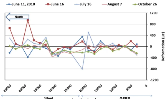
The strain variation in the reinforcing bars (GFRP and steel) was recorded with the FOS, VWSG, and ESG, and plotted in Figures 10 to 13 depending on the location of the instrumented bars in the barrier section. It should be noted that the strain values presented in these four figures which were measured between June 11 to October 26, 2010, were specifically selected for times when the temperature was equal to 20±1°C in order to eliminate the effect of temperature on the recorded strain. Also, the measured temperature variation inside the barrier wall is presented in Figure 14, where the effect of cement hydration heat can be clearly observed during the first day after casting, after that time the concrete temperature followed the ambient air temperature.
Figure 10: Strain profile in the bottom instrumented bars - East side ‐1200 ‐800 ‐400 0 400 800 1200 De fo rm a ti o n ( με ) Location (mm)
June 11, 2010 June 16 July 16 August 7 October 26
Steel GFRP
North
Figure 11: Strain profile in the bottom instrumented bars - West side ‐1200 ‐800 ‐400 0 400 800 1200 De fo rm a ti o n ( με ) Location (mm)
June 11, 2010 June 16 July 16 August 7 October 26
North
GFRP Steel
Figure 12: Strain profile in the top instrumented bars - East side ‐1200 ‐800 ‐400 0 400 800 1200 De fo rm ation ( με ) Location (mm)
June 11, 2010 June 16 July 16 August 7 October 26
Steel GFRP
North
Figure 13: Strain profile in the top instrumented bars - West side ‐1200 ‐800 ‐400 0 400 800 1200 De fo rm atio n ( με ) Location (mm)
June 11, 2010 June 16 July 16 August 7 October 26
Steel GFRP
North
Figure 14: Temperature variation in the median barrier
‐15 ‐10 ‐5 0 5 10 15 20 25 30 35 40 45 50 9 ‐Jun 10 ‐Jun 11 ‐Jun 12 ‐Jun 13 ‐Jun 14 ‐Jun 15 ‐Jun 16 ‐Jun 17 ‐Jun 18 ‐Jun 19 ‐Jun 20 ‐Jun 21 ‐Jun 22 ‐Jun 23 ‐Jun 24 ‐Jun 26 ‐Jun 28 ‐Jun 30 ‐Jun 2‐Ju l 4 ‐Ju l 6 ‐Ju l 8 ‐Ju l 10 ‐Jul 12 ‐Jul 14 ‐Jul 16 ‐Jul 18 ‐Jul 20 ‐Jul 22 ‐Jul 24 ‐Jul 7 ‐Au g 9 ‐Au g 11 ‐Aug 13 ‐Aug 15 ‐Aug 17 ‐Aug 19 ‐Aug 21 ‐Aug 23 ‐Aug 25 ‐Aug Te m p e ra tu re (°C) Date
VWSG‐Bottom Steel Bars VWSG‐Bottom Steel Bars THT‐Bottom Steel Bars THT‐Bottom GFRP Bars THT‐Top Steel Bars THT‐Top GFRP Bars
From Figures 10 to 13, it can be first observed that the strain variation recorded at the bottom bars in the East side of the barrier was small in comparison to the other instrumented bars. It can also be observed that the strain variation in the top bars was higher than in the bottom bars of the barrier. This is attributed to the restraint from the bridge slab, which affects more the deformation at the bottom of the barrier than at the top. However, higher tensile stresses should be expected to develop where the restraint is higher.
5. Concluding Remarks
EM-112-10
• Both of GFRP- and steel-reinforced barrier sections exhibited early-age cracking. The initial maximum crack widths in both sections were 0.15 mm and 0.18 mm for the steel- and GFRP-reinforced sections, respectively, which is similar.
• Transverse cracks in both GFRP- and steel-reinforced sections formed in the first 4 weeks after removing the formwork, indicating the stabilization of the crack pattern in only 4 weeks.
• The crack widths in the GFRP- and steel-reinforced sections increased for about 4 weeks after removing the formwork due to the increasing temperature. However, the GFRP-reinforced section showed larger crack widths than steel-reinforced sections due to their lower stiffness.
• The variations in the recorded longitudinal strains and in the measured crack widths were observed to follow the seasonal variation of temperature.
• It has been tentatively shown that the short-term structural behaviour of barrier sections reinforced with 14 longitudinal GFRP bars is equivalent to that of barrier sections reinforced with 8 or 12 galvanized steel bars.
• The long-term monitoring of the bridge barrier will enable a better understanding of the behaviour of the GFRP- and steel-reinforced barriers under real environmental conditions and the optimization of bridge barrier designs of Type MTQ 202ME.
6. Acknowledgments
The authors would like to express their special thanks and gratitude to the Natural Science and Engineering Research Council of Canada (NSERC) and The Ministry of Transportation of Quebec (MTQ). The authors are grateful to the consulting engineering firm Teknika-HBA Inc. The authors would also like to thank the technical staff of the structural laboratory of the civil engineering department at University of Sherbrooke for their help with the bridge instrumentation in this project.
7. References
Ahmed, E., Dulude, C., and Benmkrane, B. (2011). “Static and Dynamic Testing of 210 and 311 Bridge Barriers Reinforced with GFRP Bars.” Final Technical Report, Submitted to the Ministry of Transportation of Quebec, Structure Division, February, 129p.
Benmkrane, B., Dulude, C., Ahmed, E., and El-Gamal, S. (2009). “Static and Dynamic Testing of 210 and 311 Bridge Barriers Reinforced with GFRP Bars.” Progress Report No. 1, Submitted to the Ministry of Transportation of Quebec, Structure Division, September, 121p. (In French).
Benmokrane, B., El-Salakawy, E., El-Gamal, S., and Goulet, S. (2007a). “Construction and Testing of an Innovative Concrete Bridge Deck Totally Reinforced with Glass FRP Bars: Val-Alain Bridge on Highway 20 East.” Journal of Bridge Engineering, 12(5): 632–645.
Benmokrane, B., El-Salakawy, E., El-Ragaby, A., and El-Gamal, S. (2007b). “Performance Evaluation of Innovative Concrete Bridge Deck Slabs Reinforced with Fibre-Reinforced Polymer Bars.” Canadian
Journal of Civil Engineering, 34(3): 298–310.
Canadian Standards Association (CSA). (2010). “Specification for fibre-reinforced polymers.” CAN/CSA S807–10, Rexdale, Ontario, Canada, 27p.
Cusson, D., and Qian, S. (2009). “Ten-Year Field Evaluation of Corrosion-Inhibiting Systems in concrete Bridge Barrier Walls.” ACI Materials Journal, Vol. 106, No. 3, pp. 291-300.
Cusson, D., and Repette, W. L. (2000). “Early-Age Cracking in Reconstructed Concrete Bridge Barrier Walls.” ACI Materials Journal, Vol. 97, No. 4, pp. 438-446.
El-Salakawy, E., Benmokrane, B., Masmoudi, R., Briere, F. and Breaumier, E. (2003). “Concrete Bridge Barriers Reinforced with Glass Fiber-Reinforced Polymer Composite Bars.” ACI Structural Journal, Vol. 100, No. 6, pp. 815-824.
Matta, F. and Nanni, A. (2009). “Connection of Concrete Railing Post and Bridge Deck with Internal FRP Reinforcement.” ASCE Journal of Bridge Engineering, Vol. 14, No. 1, pp. 66-76.
Pultrall Inc. (2010). “Product technical specifications.” ADS Composites Group Inc., Thetford Mines, Québec, Canada, <http://www.Pultrall.com>
Sennah, K., Tropynina, E., Goremykin, S., Lam, M., and Lucic, S. (2010). “Concrete Bridge Barriers Reinforced with GFRP Bars with Headed Ends.” Proceedings of the 8th Short and Medium Span Bridge Conference, Niagara Falls, Canada, 10p.