Automated Design of Modular Field Robots
by
Nathaniel
Rutman
BSME Stanford University (1991)
Submitted to the Department of Mechanical Engineering in Partial
Fulfillment of the Requirements for the Degree of
Master of Science
at
the
Massachusetts Institute of Technology
June 1995
@1995 Massachusetts Institute of Technology. All rights reserved.
Signature of Author
Department of Mechanical Engineering May 1995 Certified by (-/ Sfvhn Dubowsky -. - -Th6sis Supervisor Accepted by Ain A. Sonin Chairman, Departmental Graduate Committee
;4ASSACHUSETTS INSTITUTE OF TECHNOLOGY
AUG
31 1995
LIBRARIES Barker Eng /VAutomated Design of
Modular
Field Robots
by
Nathaniel
Rutman
Abstract
Robots are needed for important missions in field environments. A major
limitation to the practical use of such systems is their high cost and long development time. It would be highly desirable to have systems that can be rapidly designed and fabricated, on the order of days or weeks instead of years. One approach to achieving this goal is the development of an automatic design methodology based on the use of standardized modular physical components.
The objective of this research has been the development of a framework for
the automatic design of modular field robotic systems. Under this
methodology, robots are assembled from sets of modular components. The assembly method as well as the component designs are based on fundamental solid engineering principles.
This thesis includes the generation of computer-based design search algorithms. The framework utilizes a hierarchical search over the possible
robot assemblies. Physics-based rules are used to limit the search to
"reasonable" assemblies. Assemblies are analyzed and ranked according to their ability to perform a given task. The methodology was used to suggest a robot for an inspection task aboard the USS Constitution.
Supervisor: Dr. Steven Dubowsky
Table of Contents
CHAPTER I: INTRODUCTION 7
Motivation 7
Objectives 9
Background and Literature 10
Modular Design 12
Evaluation 15
CHAPTER 2: CONTINUOUS VS. MODULAR DESIGN SPACE 16
CHAPTER 3: MODULAR DESIGN METHOD 18
Domain 19
Task Structure 20
Assembly Structures 22
Assembly Representation 28
Search Hierarchy 29
CHAPTER 4: DESIGNING MODULAR COMPONENTS AND INVENTORIES 34 Good Design Characteristics for Modular Components 34
Design Via Frequency in Solutions 37
Design Via Usage in Solutions 38
Design Via Modular Design Algorithm 39
CHAPTER 5: OTHER ISSUES 40
Growth of Design Space 40
Level of Modularity 40
Search Method Comparison 41
Sensing, Control, and Communications 43
CHAPTER 6: APPLICATION TO THE USS CONSTITUTION 45
Constitution Task Description 45
Parts inventory 47
The Search Process 49
CHAPTER 7: RESULTS 62
Solution of the Constitution Task
Validity of Solutions 65
Growth of Search Space 66
Effectiveness of Tests on Search Size 68
CHAPTER 8: COMPARISON WITH TRADITIONAL DESIGN METHODS 72
Traditional Design of Constitution Robot 72
Comparison with Modular Design 75
CHAPTER 9: CONCLUSIONS 78
Direction of future work 78
BIBLIOGRAPHY 80
APPENDIX: MODULAR DESIGN PROGRAM 85
Usage 85
Output 86
Table of Figures
Figure 1. A concept for a field robotic explorer 8
Figure 2. A sample set (inventory) of modular components 13
Figure 3. A system assembled from a limited inventory of modular components 13
Figure 4. More assembled robotic systems 13
Figure 5. The multiplying effects of hierarchical filtering. Removal of a bad kit
eliminates the subsequent analysis of all its child assemblies 15
Figure 6. A continuous design space of a conventional system 17
Figure 7. A discrete design space of a modular system 17
Figure 8. A reduced discrete design space of a modular system 17
Figure 9. A physically structured search process 19
Figure 10. A schematic of the USS Constitution bilge area 20 Figure 11. Analytical solutions depend on task representation 21
Figure 12. Simple task representation 21
Figure 13. Levels of robot structures 23
Figure 14. These kits can never produce useful robots 27
Figure 15. Assembly representations. The robot body and one limb are shown. 28
Figure 16. Leg step height versus wheel diameter 35
Figure 17. Adding a genetic algorithm search 43
Figure 18. Constitution hold cross-section 46
Figure 19. View looking inboard. Diagonal riders compartmentalize the space. 46 Figure 20. Modular robot output from the automatic designer 49
Figure 21. Asymptotic function 55
Figure 22. Each joint must lift the rest of the limb 58
Figure 23. Design solutions for the task and inventory 62
Figure 24. A different evaluation function 63
Figure 25. Another evaluation function 64
Figure 26. A higher ranked robot and a lower ranked robot 65
Figure 27. Combinatorial growth of search size with number of modules 66
Figure 28. Search time versus number of kit size 67
Figure 29. Computations for tests 68
Figure 30. Filter efficiency 69
Figure 31. Filter effects on search computations 70
Figure 32. Alternative rough design sketches 72
Figure 33. Most promising design is roughly dimensioned 73
Figure 34. Refined overall robot design is sketched 73
Figure 35. Detailed design sketches 74
Figure 36. Design process comparison 76
Acknowledgments
This work is the result of a research program sponsored by the NSF under its Small Grants for Exploratory Research (SGER) Program #IRI9320138 and by
NASA grant #NAG11632.
I would like to thank my advisor, Dr. Steven Dubowsky, for providing the
broad vision and direction for this thesis, and the opportunity to work on several interesting projects at MIT. I would also like to thank my fellow graduate students for their advice, humor, and fascinating discussions.
Chapter
I:
Introduction
This thesis studies the fundamental technical issues and problems of applying mobile robotic systems in complex, and possibly remote unstructured field environments, such as might be found in systems performing civil infrastructure inspection and maintenance tasks. The major focus of the research has been to develop a design framework so that robots can be assembled automatically from sets of modular components. The research has been performed in connection with a demonstration project called The Project Constitution.
Motivation
Robots are needed for field environments
Robots are needed for important missions in field environments [1, 2]. These
systems could perform such important tasks as maintenance and disaster
mitigation in nuclear power facilities, cleanup of toxic and hazardous waste
sites and chemical accident cleanup, terrorist bomb disposal, infrastructure
inspection, and commercial tanker hull maintenance [3, 4, 5, 6]. For many of
these missions, robotic systems could remove humans from dangerous tasks
or enter locations that are not readily accessible. In some applications, such as
the inspection of the undersides of highway and rail bridges, robotic systems
could also be very cost effective.
A great deal of research has been done to develop robotic manipulators
(usually a fixed based single arm) for work in manufacturing cells structured
specifically for them. Some research is now being done to develop field
robotic systems that are able to perform missions where the task and
environment are not well known and the system must be capable of mobility
as well as being able to manipulate and investigate the environment [7, 8, 9],
see Figure 1 [10].
Command Center SCAM System
Radio or Acoustic
Communications el
control Link [Autonomous
rnntrnl
High Level Commands
Communications HihLvlCm d Communications
Hardware Survey Data I
Data Storage & Batteries
Analysis
Control Sensors
Data Instruments
Figure 1. A concept for afield robotic explorer
Challenges facing these systems are that they must be robust, self-contained, power efficient, dexterous, agile, and have a high degree of autonomy. Besides these technical challenges, a major future limitation to the practical use of such systems is their cost and their development time. The design and development cost of such systems using current approaches would be prohibitive for many applications. This is largely because these systems will not be mass produced; each system would need to be designed for a specific mission or task. Not only will their costs be very high but the systems development time for a given mission could take years, when deployment in
weeks or months may be required. For this reason it would be highly
desirable to have systems that can be rapidly designed and fabricated.
One very promising approach to achieve this goal for field robotic systems is the development of a design methodology based on the use of standardized modular physical components, and control and planning algorithms and software that are compatible with a modular structure. To date, no other quantitative methods to rapidly design a field robotic system using modular components for a given mission have been developed.
ow Baud Rate Commands
Low Baud Rate
Survey Data
M
Rapid deployment
Clearly, methods that would permit the rapid assembly and deployment of cost effective field robotic systems using standard modular components
would make these systems practical for many important missions. As
discussed below, in this research the USS Constitution (Old Ironsides) serves as a testbed for evaluating many of the research results. This permits the experimental testing of the design methods developed in this fundamental research program for a practical mission. The modular design techniques are used to suggest several candidate robotic designs for the Constitution.
Other advantages of modular systems
Using modular parts and designs leads to higher production volumes and
lower part costs. Robots with modular components can be easily and quickly
repaired by replacing a defective module. Additionally, the modular part
inventory can be improved off-line, allowing aging modular robots to be
updated to state-of-the-art technology with little redesign or down-time.
Objectives
The objective of this research program has been the development of a
rational design framework for automatically designing robots based on task
requirements using a set of modular components. With this modular design
approach, robotic systems for missions in unstructured field environments
can be designed and deployed rapidly and cost effectively. Computer based search algorithms are implemented to quickly and automatically find appropriate candidate designs.
It will be shown that simple tests can screen large numbers of alternative
robot designs to quickly yield a few candidate designs which are believed to
have the potential to perform a given task well.
This research does not attempt to plan the actions of the robot for the
performance of the task. Instead, for a fixed task and solution domain, certain
solid engineering principles. These characteristics are tested in a computationally efficient manner. Related research covered in other theses includes the development of modular planning [11] and control algorithms.
Background and Literature
To date a number of field robotic systems have been developed and proposed for specific applications. Systems have been designed to work on construction sites, to crawl through small-diameter gas lines, and climb up walls [4, 12, 13]. Systems are being developed for specific tasks in the service industry, to act as a nurse's aide, to perform sentry duty, to clean and to care for the elderly, or to prune grape vines [14, 15, 16, 17, 18, 19, 20, 21]. While some of these systems may prove to be effective, some have demonstrated the limits of current technology. For example, Dante, a system designed to explore the insides of volcanoes, did not perform as hoped during its initial field tests because of difficulties with its umbilical cable [22]. Clearly, if the technical problems with designing self-contained systems could be solved these systems would be more robust.
In the past, most design studies in robotics dealt with the problems of
"classical" fixed-base industrial manipulators. Many of the results of this
work have entered engineering practice [23]. More recent research has
focused on such issues as the development of new and innovative components, sensors or computer architectures for robotic systems [24, 25, 26,
27]. Recently, significant research has been devoted to developing
micro-mechanical precision and new exotic components for robotic applications [28,
29, 30, 31, 32]. However, robotic systems for field missions need to be quite
different from conventional fixed base inanipulators commonly used in industry, see Figure 1.
Research into designs with potential use in field applications has studied mobility methods based on walking, climbing and crawling [6, 9, 33, 34, 35, 36, 37, 38, 39, 40, 41, 42]. As a result of this research a number of very innovative
specific designs have been developed and demonstrated for field systems and
for simple laboratory systems [8, 43, 44, 45, 46, 47]. Also some interesting
lessons on the design of mobile robotic systems have been obtained from studying biological systems, such as animals and insects [48, 49, 50]. Some studies of mobile systems have attempted to develop design methods based on fundamental mechanics, such as developing design rules for motor selection to avoid actuator saturation and to minimize systems power consumption [7, 51]. It is interesting that most of the studies on the design of field robotics referred above have largely focused on achieving mobility
without manipulation. However, there have been some important
exceptions [52].
What is clear from an examination of the past research in field robotic systems is that is has either dealt with development of specific technology, or with a specific "one of a kind" system. Little or no work has been done to develop general methods to aid in the rapid design of field systems. It would be of great benefit to have general methods for designing field systems that consider the important attributes for a given task, and then quickly yield the configuration and design parameters of robotic system that is capable of meeting the mission's functional requirements.
In recent years there has been some important work done exploring some of the issues of industrial manipulators constructed with modular components. These studies include research dealing with the mechanical design [53, 54] the kinematic modeling [55, 56, 57], the enumeration of assembly configurations
[58], the configuration selection based on computer aided design techniques [59] or on expert systems [60], the design based on task requirements [61, 62],
and fault tolerant design [63]. This research has focused on industrial-type manipulator systems; systems consisting of relatively simple open loop chains of links operating from fixed bases. Such systems are very different from field systems that must be capable of mobility as well as manipulation, such as shown schematically in Figure 1.
The performance required of these field systems is quite different, arguably
more difficult, than those for industrial systems [64]. For example the
precision of an industrial system is often paramount. In field systems the need for the system not to turn over while moving, or for a battery powered system, not running out of power [51, 65] can be the critical issues. Such issues can make any design method very difficult, in part because in a field environment, unlike a factory, the task and the environment are not well controlled, or possibly even well known. This makes the modular design a
challenging problem. While we are aware of one specific field system
designed with a modular character this was done on an ad-hoc basis [4]. The development of general techniques to design modular field robotic systems remain a virtually unexplored problem. Such design methodologies would need to consider the fundamental limitations of the physical hardware, such as actuator saturation characteristics and battery life profiles that are available for field robotic systems. They should be able to quickly assemble system designs from modular subsystems and components. These methods should be based on fundamental engineering principles to insure they have the flexibility to be used for a wide range of systems and missions.
Modular Design
Modular robots
The key to this approach for achieving cost-effective and rapidly deployable multi-limbed mobile field robots is the use of modular components. Figure 2 shows, schematically, a relatively small set of modular components. Figure 4 and Figure 4 contain just three of the many possible systems that can be obtained from this inventory of modules. A real inventory might contain more, but possible not a great deal more, component types. Components of various sizes might also be included.
betkWyibody Ink rotwy whsr wh O roe bMp OnwWokt
K
Tf
A
Figure 2. A sample set (inventory) of modular componentsx '. xxxxx x xx~
Figure 3. A system assembled from a limited inventory of modular components
Figure 4. More assembled robotic systems Small inventory of parts yields wide selection of robots
Modular systems make sense in the context of automated robot design and assembly. As shown in this thesis, using a simple set of fixed rules, modular systems can be automatically generated and tested. Combining a small set of modules in different ways permits an assembly space of many topologically diverse robots. A modular system can automatically span this space.
VW9HNnIrIrrII
ri
Most of the possible robots are not useful
Of the many possible robots, only a small fraction are useful. The vast majority will contain one or more features that precludes the possibility of a useful robot. If these features can be recognized, then such robots might be quickly discarded, or avoided altogether.
There are too many to consider in a conventional way
Even with modem high-speed computers, the combinatorial explosion of the number of robots precludes analysis of every possible assembly.
The number of robots (actually, the number of kits, explained below in Kits,
page 26 - basically, a kit is an unassembled group of modules) that can be
produced by taking exactly r modules of n unique types with replacement is
(r + n- 1)! [66]. Thus, using up to 30 modules of 12 unique types yields 11
n! (r - 1)!
billion possible robots (note the expression given is for exactly r modules, not up to r modules. The sum of these expressions with r running from 1 to 30
yields the 11 billion.) If the entire algorithm took only 1 millisecond to
conduct per robot, a computer would still require 127 days to execute.
Hierarchical selection process to avoid combinatorial explosion
The key to the development of a practical method for automatically generating robot designs is a hierarchical filtering process that reduces the design space at every stage, see Figure 5. At each added level of complexity (topological or structural) broad regions in the design space are eliminated, minimizing the total number of assemblies to be analyzed. This method is hierarchical because it eliminates entire sub-trees from consideration, multiplying its effects in every subsequent level.
Parts
size
OP
Kits
'F
0
Assemblies
Figure 5. The multiplying effects of hierarchical filtering. Removal of a bad kit eliminates the subsequent analysis of all its child assemblies
Simple tests can quickly distinguish between remaining assemblies
Assemblies that make it through the filtering process must be evaluated in
terms of how well they can perform the required tasks. A numerical
objective function based on diverse features of the assemblies is used in a search for the best candidate robot for the task. This objective function is the sole element determining the outcome of the search. An important aspect of this research has been the development of a computationally cheap objective function that can reasonably predict robot performance, and therefore deliver useful robots.
Evaluation
This thesis seeks to address the advantages and limitations of the modular design approach. The research uses simulations and analytical studies to evaluate the results obtained. This approach has been undertaken within the context of multi-limbed field robots, using The USS Constitution as a demonstration project. The modular design techniques are developed and implemented in a software system, a modular inventory is designed, and the
system is used to suggest several inspection and treatment robotic systems for the Constitution. ~C
/%
/
\
Z
\
Z
N
00
rChapter 2: Continuous vs. Modular Design
Space
In some important ways, the design of a modular system can be simpler than the design of a conventional system. The design space of a modular system, given a set of available modules, can be represented by a finite set of possible assemblies, while the non-modular design space is, in theory, infinite.
Figure 6 conceptually shows a two dimensional non-modular (continuous) design space. The vertical axis symbolizes the robot performance, while the two independent design variables (a and 3) can assume any value in their
range. Figure 7 shows the corresponding modular design (ai, bj, i = 1, 2, ... n, j
= 1, 2, ... m). There is now a finite series of systems that can be composed of
two components that are allowed only discrete values. The values are
constrained by the available inventory, made up of n a-types and m b-types. For systems with more components the dimensionality of the space would grow. While the modular space has a finite set of components, the number of assemblies that can be made, as mentioned above, grows very rapidly. For any real problem an exhaustive evaluation of all possible designs is out of the question. The key to a practical search lies in reducing the search space to a computationally feasible size. Such a space is indicated in Figure 8 where a number of the discrete design values have been eliminated using a method such as the hierarchical physics based method described by this thesis. In Figure 8 only systems with estimated good performance remain. At this point it becomes feasible to evaluate the performance of these "good candidates" in detail.
Figure 6. A continuous design space of a conventional system
1 1
Figure 7. A discrete design space Figure 8. A reduced discrete of a modular system design space of a modular system
Chapter 3: Modular Design Method
In this research structured hierarchical procedures are formulated to search and evaluate the performance of possible assemblies of modular components. The methods are framed to exploit the physical nature of behavior of these
systems and their tasks and environments. The methods also attempt to
achieve effectiveness by recognizing that some of the performance characteristics of these systems are much easier, and computationally efficient, to predict than others [67]. For example, it is much easier to evaluate
a candidate design configuration's static stability - if it will fall over - than the
communication data rates required to control it in a given mission. The modular search algorithm applies the simplest tests first to prune the set of all possible designs and quickly converge on a small set of candidate assemblies
of modular components. Only the successful candidates need to be
considered by the later, more computationally intensive tests [7].
Figure 9 shows the search method schematically. This figure is referenced and explained throughout the remainder of this thesis.
Figure 9. A physically structured search process
Domain
Task domain
The modular design approach has been applied to the domain of field robotic applications in partially known, complex environments.
Solution domain
The solution domain is restricted to the class of multi-limbed, static walking robots. These robots should be self-contained in order to function in extreme
field environments. In general, the robots are capable of force manipulation of the environment to some degree.
Task
Structure
Sample task
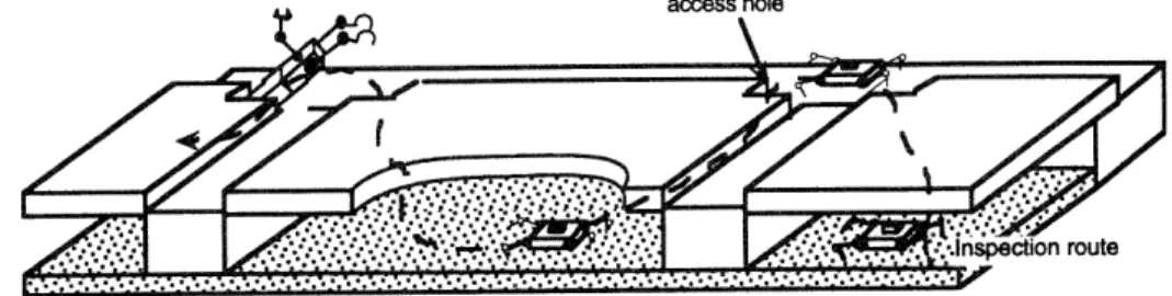
For purposes of illustration, the modular design method will be described with a sample task in mind. The task is taken from the USS Constitution, where a robot is needed to inspect wood surfaces in the bilge of the ship for rot. This area is shown schematically in Figure 10.
Mr-'acc hrla
Figure 10. A schematic of the USS Constitution bilge area
Further details of this task can be found below. Representation
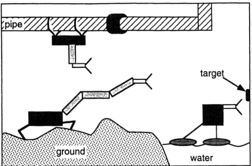
If a detailed model of the task environment was known beforehand, highly specialized robots might be valid solutions. In Figure 11, the task is to reach the target with a gripper. Knowledge of the pipe diameter and material, exact location of the target object, size of the fitting, location of the bend, etc., as well as access to one end of the pipe would be required to implement the pipe
hanging robotic solution. Knowledge of the water extent, depth,
Figure 11. Analytical solutions depend on task representation
Figure 12. Simple task representation
A simpler task representation is shown in Figure 12. The task is described in simple terms with a limited number of concise constraints, such as the maximum span and maximum step required. Since the solution domain is limited to walking, limbed robots, the constraints were developed for this domain. If the solution domain included pipe-crawling or floating robots, then constraints appropriate for these domains would be included as well.
target
maximum step
n :.... maximum span
The task is described via these simple constraints for two reasons. First, because the task domain is in field environments, exact knowledge of the environment is unavailable. The constraint method eliminates the need for complete detailed environmental knowledge. Second, simple constraints lend themselves naturally to simple tests, which are the basis for the hierarchical search method.
If all the constraints are met, then it is assumed that the robot can perform the task adequately. This thesis does not involve the analysis of more complex plans [11] to determine task adequacy.
Weighting factors are also included in the task representation. These are used to achieve the desired mix of cost, running time, and reliability appropriate to the task. Other factors, such as robot mass, are not given weighting factors because they are used only as constraints; as long as the robot mass is under 9
kg, the robot is acceptable.
Constraints are geometric (maximum step size required, maximum span to be
crossed, minimum hole size the robot must crawl through), static
(maximum force to be applied against the environment), kinematic
(maximum payload to be lifted), and environmental (all modules must work in the dark and wet for the sample task.) Additionally, a list of required end-effector capabilities (the sample task requires 4 feet that can operate on a
horizontal wooden surface, and 1 gripper.) Other constraints include
maximum mass allowed, minimum required operating time. Cost is also used as a constraint, as well as a weighting factor.
Assembly Structures
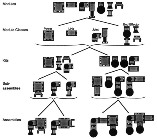
In the design methodology presented in this thesis, five levels of structure are used to develop robots, see Figure 13. First, individual modules are designed
in full detail. These modules are then grouped together by function.
From the kits, subassemblies are constructed. Finally, the subassemblies are combined into full robot assemblies.
Modules Module Classes Kits Sub-assemblies
-Fulai
End Effecomm-Yr
AssembliesFigure 13. Levels of robot structures
These five levels of structure were chosen because general physical rules can
be applied at each level. These rules can determine whether subsequent
assemblies will be reasonable robotic solutions. Every structural level
provides additional rules, helping reduce the solution search space. The organizational overhead of maintaining multiple structural levels is insignificant compared to the computational savings realized through the use of these rules.
Modules
The individual modules used in the automated design algorithm are designed in detail before the search can begin. Evaluations used during the search depend not only on general characteristics of the modules, such as
classification type, but on actual physical characteristics as well, such as
weight, maximum torque, power consumption, and material properties.
Different evaluations and tests used throughout the search use models of
varying complexity extracted from the full module model. For example, a test
for static strength may depend on a lumped mass model of the modules, while a dynamic stability test may require a moment of inertia matrix.
By knowing all the details of the modules in advance, the refining process of
traditional design is eliminated. A potential robot can be described
completely from its modules and their organization. The robot's capabilities are accordingly completely calculable as well. This feature is necessary for ranking robots' task performances.
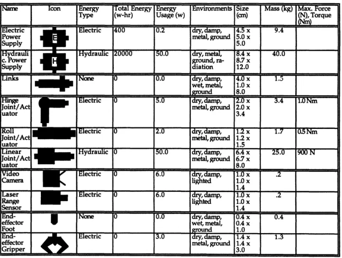
Table 1. A sample modular parts inventory
Name Icon Energy Total Energy Energy Environments Size Mass (kg) Max. Force
Type (w-hr) Usage (w) (can) (N), Torque
Electric Electric 400 0.2 dry, damp, 4.5 x 9.4
Power metal, ground 5.0 x
Supply 5.0
Hydrauli Hyraulic 20000.0 dry, metal, 8.4x 40.0
c. Power ground, ra- 8.7 x
Supply diation 12.0
Links
0.0
dry, damp, 4.0
x
1.5
wet, metal, 1.0 x
Sgrond 8.0
Hin Electric 0 5.0 dry, , 2.0 x 3.4 1.0 Nm
Joint/Act metal, ground 2.0 x
uator 3.4
Joint/Act metal, ground 1.2 x
metal, ground
6.7 x
80I
I.V
ectFric
0
6.0
dry,
damp'
1.0 x
.2
lighted 1.0 x
1 4
Cameral
Electric 0 6.0 dry, damp 1.0 x .2
lighted 1.0 x
Sensor 1.4
End- None 0 0.0 dry, damp, 0.4 x 0.4
effector wet, metal, 0.4 x
Foot _ground w 1.0
End- Electric 0 .0 dry, damp, 1.4 x 1.3
effector metal, ground 1.4 x
Gripper 3.0
uarLr Joint/Act
n•atrw
Module Classes
The modular parts inventory is divided into subclasses based on functionality. The four subclasses used are power supply modules, actuated limb segments, passive structural link segments, and end-effectors, see Figure
13.
* Power modules supply power to the other connected modules. Most
commonly these would be battery based, but a gasoline-powered air pump might also be used as a pneumatic power source, or a module with a self-winding power cord attached to a fixed power station if self-containment was not necessary. Power modvles would come in a variety of capacities. Also, because they are used in the center-body of all robots (see
Subassemblies, below) power modules have multiple connection
locations, or ports, where other modules can attach to them.
* A passive structural link segment, or link, passively connects two other modules together, rigidly, a fixed distance apart. Key features of links are material properties such as strength and stiffness.
* An actuated limb segment also connects two other modules. These
modules consist of an active actuated joint of at least one degree of
freedom, combined with a rigid beam. Because the major difference
between these modules and links is the addition of the actuated joint, these modules will be called joints for the remainder of this thesis. Joints use power provided by an appropriate power module, and can be characterized by applicable torques and speeds.
* The final category is end-effectors, such as grippers or feet, or wheels in a
wheeled system. End-effectors come into direct contact with the
environment on one end, while the other attaches to another module.
All modules have some common features, such as size, weight, reliability,
classes have additional specific parameters - actuated limb segments and end-effectors have a required power type (i.e. electrical or hydraulic) and maximum torques. Power modules have an energy storage capacity.
These module classes were organized by functionality so that structural analyses could be simplified. This decision has worked well in practice, but it has proved beneficial to further subdivide the end-effector class into feet and grippers for certain analyses. Other organizations, such as by power type or operable environments, have not been found to be as widely useful in this search hierarchy, because they do not lend themselves to structural analysis as easily. These properties are therefore accessed as attributes of individual modules, and not as module classes.
Kits
A kit is an unassembled group of modules, which might later be assembled
into a robot, see Figure 13. Typically, a kit can be assembled in many different ways, producing many topologically diverse robots. All modules within a kit must be used in the assemblies made from that kit. (If a module was not used, the remaining modules would simply constitute a smaller kit.)
However, there are some kits that can never produce useful robots, no matter how they are assembled. The physically based kit selection rules shown in Figure 9 eliminate these fundamentally flawed kits. For instance, a robot with a hydraulic power supply and electric actuators cannot function in any assembly; similarly, a robot made up of only "feet" will never be useful, see Figure 14. These kits are simply not produced by the modular design algorithm, effectively pruning large areas of the design space as in Figure 5 and Figure 8.
VW
Figure 14. These kits can never produce useful robots Subassemblies
Kits are then organized into subassemblies of a center body and serial-link limbs, see Figure 13. Subassemblies are created according to certain physical rules that eliminate "nonsense" structures. Every limb must end in an end-effector and contain at least one joint. The center body must contain all the power supplies (by definition) and can also contain links and joints, but not end-effectors.
The subdivision into center body and limbs is a consequence of the stated solution domain, multi-limbed walking robots. In other solution domains, different subassembly types might be required.
It can be argued that limbs do not necessarily need to be serial. This then blurs the distinction between center-body and limbs, and eliminates most of the consequential subassembly rules. If subassemblies are eliminated, as indeed they can be, more full assemblies must be tested.
The tradeoff between more structured and more open classifications, as in most areas of the modular design algorithm, is in the incremental performance benefit provided by allowing more assemblies versus the
increased design space to be searched at later (and more complex) tests.
Assemblies
As shown in Figure 9, the subassemblies are combined in various
arrangements into completed robot assemblies. This is facilitated by a
minimal set of assembly rules, which simply insure that legs are connected to the center body, and that there are at least four legs (to allow static walking. This rule could be relaxed if dynamic walking was allowed in the solution
domain.) Assemblies are fully defined representations of actual robots, and can be used in simulations or evaluations, or constructed out of parts from the modular inventory and inserted into the task field environment. Good assemblies will be able to perform the task well.
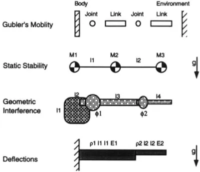
Assembly Representation
Modules are described in full detail. Assemblies can be described in full detail
if the component modules are known, and the order in which they are
connected is known. The assembly is therefore represented internally as a connection diagram. Different tests can extract the features they need from the assembly description and the module descriptions, as in Figure 15.
Body Environment
Joint Unk Joint Unk
Gubler's Moblity 00 0 0 C M1 M2 M3 Static Stability 11 12 g Geometric p Interference
1
p I1 I1 El p2 12 12 E2 Deflections4
Figure 15. Assembly representations. The robot body and one limb are shown.
Figure 15 lists some assembly tests and the relevant information from the assembly that is needed by the test. These tests are described in detail in Chapter 6: Application to the USS Constitution. Grubler's mobility test requires only the type of joints or links and their order. A static stability test
requires the relative positions of mass concentrations. A geometric
interference check requires full dimensional knowledge and the location and ranges of joints. A deflection under loading test requires the lengths and
material properties of the limb segments. Not shown in the figure, a full dynamic simulation would require mass moment of inertia matrices, relative positions, actuator torques and speeds, etc. These representations are derived
as needed during the tests. See Table 2 for other test information
requirements.
Table 2. Required information for tests.
Test Required knowledge
interference dimensions, motion ranges
static forces dimensions, torques
mobility topology, static forces
static forces dimensions, torques
static stability center of mass, foot positions
deflections material properties, moments of
inertia
accuracy dimensions, backlash, deflections,
sensor accuracy
dynamics dimensions, joint velocities,
moments of inertia, torques
kinetostatics dimensions, joint velocities, joint
accelerations, moments of inertia
power consumption torques, actuator efficiencies
speed dimensions, joint velocities, joint
accelerations
These tests are designed to be independent of the task and the plan. They only use information available in the module descriptions and the assembly representation.
Search Hierarchy
Physical-based rules determine how assembly structures are constructed. Additionally, task-based filters are used at several points throughout the search to further prune the solution space. The distinction between rules and filters is that rules always hold true, regardless of the nature of the task, and filters are task-dependent. A rule might be: the robot must stand statically; and a filter might be: the robot must weigh less than 20 lb. Finally, numerical
evaluations of the structures are used as ranking functions. An evaluation might give robots with low weights better scores. Evaluations can be task-dependent or not. Rules, filters, and evaluations are collectively referred to here as tests.
Filters
Filters remove from consideration any modules, kits, or assemblies that cannot meet certain task requirements. Note that filters do not insure that a
passing candidate will be able to meet that task requirement -passing a filter is
generally a necessary but not a sufficient condition to insure task compliance. For this reason, filters can be kept simple, saving computational effort for later in the search, when there will be fewer candidates to consider.
For instance, one assembly filter may be a test to see if a robot can walk. A full test of walking ability might require a full dynamic simulation of the robot, which, although possible, is a computationally expensive procedure. However, a quick-and-dirty walking test might be: check that each foot can be
lifted individually without the robot falling over. This test will still
eliminate many, but not all, candidates that cannot walk; foot-lifting ability is one of a number of requirements for walking.
Filters are arranged at each structural level according to their complexity and ability to eliminate assemblies. Computationally simple filters that eliminate a wide selection of robots are the most useful in terms of search speed; later filters that involve more computation will have to be applied on fewer robots. The effects of filter arrangements are discussed in "Effectiveness of Tests on Search Size," page 68.
Module Filters
The search process begins by considering all available modules in the inventory, see Figure 9. Modules are removed from the working inventory
of parts if they do not meet some low-level task-based criteria - for example,
modules can be used. Any unsealed modules are removed from further consideration. Additionally, the task involves a spatially complex path, so a fiber-optic communications module with a tethered fiber optic line would be eliminated. Reducing the number of modules in the inventory reduces the design space as shown in Figure 8.
Using the expression on page 14, if just 3 modules are eliminated by module filters (for example, two hydraulic modules are too big to fit in the confined space of the task, and a videocamera module could not work in wet environments), the number of kits is reduced by a factor of 50 to 212 million.
Kit Filters
The kit filters, see Figure 9, insure that all feasible kits meet some aspects of the task requirements. The kits do not have to be assembled for kit filters to be applied. For example, the weight of the robot in the Constitution task is required to be under 20 pounds, so kits whose components sum total weight are greater than this are eliminated. Again, eliminating kits before they are assembled greatly reduces the design space to be searched, see Figure 5, so developing broadly applicable kit filters is an important aspect of this research.
Assembly Filters
Assembly filters eliminate assemblies based on aspects of the assembled structure. Many of the more accurate tests of the task requirements (walking ability, range of motion, or endpoint force) can only be addressed with a full assembly representation.
In the sample task, a robot is required to climb a step. A kit filter checks step height as a function of average limb length and rejects robots not capable of this action. A related assembly filter might check the step height based on the
actual, assembled limb lengths. The kit version represents a necessary
condition to climb the step. The assembly version is more complex, but represents a sufficient condition.
Extra computation time is involved in executing both filters for robots that can walk, given that the second (assembly) filter alone is sufficient. However, all of the kits rejected by the first (kit) filter have saved the computations involved in executing any remaining kit filters, setting up all possible assemblies to be made from that kit, and executing any assembly filters over all of these assemblies. The actual computational tradeoffs between test are described in Effectiveness of Tests on Search Size, page 68.
Robot Evaluations
Robots are evaluated for their potential task performance at two levels in the search structure; first for kits, then for assemblies. These evaluations are numerical and represent the quality of the solution. Robots with the higher evaluations are more appropriate for the given task. The evaluation at the kit level, including factors such as weight and cost, is used as an additional kit
filter - low scoring kits are removed - and it is for this reason that the
evaluation occurs at this level. The kit evaluation is included as a
component of the second, assembly, evaluation. The assembly with the
highest assembly evaluation score is considered the optimal robot for the given task.
Kit Evaluation
Kits that pass the kit filters are evaluated and compared to a threshold, see Figure 9. This evaluation is simple compared to the final assembly evaluation. The evaluation is the weighted sum of a series of tests, such as estimated reliability based on parts count, total cost, component inherent accuracy, power efficiency, weight, actuator speed, and predicted span. The bilge example robot needs to slowly probe closely spaced points for rot over an
area of thousands of square feet for many hours without an umbilical. Therefore, for this task, kits with estimated low static actuator power consumption would be given a high evaluation.
Kits that have scores below a given threshold are filtered out at this point, under the assumption that below some level a kit is not worth considering,
even though it may have passed all the filters up to this point. This
threshold can be changed to influence search speed and search thoroughness. Reducing the threshold to zero will allow all kits at this point to be assembled, and raising it above some maximum will eliminate all kits.
Assembly Evaluation
The final assembly evaluation computes the effectiveness of a robot for the given task. Again, the evaluation function is the weighted sum of a series of tests that include bandwidth, range of motion, mobility, walking speed, endpoint force, accuracy, and redundancy. Fast, accurate, low-cost, high-force robots would generally score well. These evaluation function in general will be more complex than previous tests, but since the number of assemblies has already been reduced significantly, the total time required for the assembly evaluations is minimized.
In the most complete incarnation of the automated modular design method, complete kinematic and dynamic models of the modules and their arrangement could be passed to external dynamic modeling programs for evaluation, such as [68,69,70], for complete dynamic simulation. Results from this simulation would be reported back to the modular design algorithm to be incorporated in the assembly evaluation.
Chapter
4:
Designing Modular Components and
Inventories
Good Design Characteristics for
Modular
Components
In designing the inventory of modular parts used in this implementation, characteristics for good modular designs were investigated. Different and new technologies and materials for actuators, sensors, structures and energy
storage elements were evaluated within this context. The characteristics
below are true in general for modular systems, but of course there will always be exceptions. Some of these characteristics are well-known, while others remain relatively undeveloped.
Some of these characteristics were incorporated into the modular inventory used in the Constitution task.
Features
Structural Features
* The scale of most mechanisms (85%) is between 3 cm and 40 cm [71]. This might be an appropriate scale in which to develop modular mechanical parts as well.
* Circular cross sections of structural components should be used because their final loading orientations are unknown [54]. Circular cross sections bear loads equally well in all directions.
Gaits
* A wheel diameter must be twice the size of a leg in order to traverse the same step height [72], see Figure 16. However, wheels are more energy-efficient than limbs because they have no dead-time in their cycles [72]. Also, static stability on wheels requires no power. So, for size-dominated tasks, limbs are better; for energy-dominated tasks, wheels are better.
Figure 16. Leg step height versus wheel diameter
* Continuous (wheeled) gaits also lead to smoother motion over flat terrain, resulting in higher speeds, more efficient energy usage, and additional stability due to rotational inertia [72].
* Statically stable gaits are safer than dynamic gaits [72]. Because the
environment is partially unknown, safety concerns dictate slower, more robust gaits.
Interfaces
* Symmetric couplings at modular connection interfaces allow for multiple orientations and redundant connectors [73].
* Hydraulic and other fluid-based modular connections are more difficult to make and maintain than electrical connections. On the other hand, they have higher power to weight ratios [54]. They should thus be avoided unless the task is power-dominated.
Transmission Features
* Most applications require high torques and low speeds [73]. Because the domain is field environments, and not manufacturing, robot actions are generally unique (non-repetitive), and because the environment is partially unknown, safety concerns dictate slower motions.
* Compared to transmissions, direct drive actuators are stiff, have no backlash, and low friction. However, they are backdrivable, have lower
torque to weight ratios, and are optimized for a particular speed and load [54].
* Harmonic transmissions have high single-stage reductions, and are accurate, repeatable, and efficient [54].
* Non-backdrivable actuators require power only when moving. For slow moving, statically stable robots (typical of field applications) these will be more energy efficient.
Technology
The following Table 3 [74,75,76,77,78] lists some well known and some unusual actuators with quantitative and qualitative ranges in which they are effective. This list is not comprehensive but is included to show the wide breadth of the field typically ignored during the design process. Modules can be refined and improved as new technologies become available, and modular robots can be improved in the field, with minimal down time.
Table 3. Some actuator types and characteristics.
type dimension frequency force power work comments
output / energy
weight density
electro- 50 Pm high 5 gF high .4 J/cm3 difficult
static output
coupling
piezo- 1mm 100 kHz 4 kgF/mm2 high 5e-4 J/cm3
electric
ultrasonic 1 cm 5 Hz high low no trans-mission
necessary
shaped .1mm 70 Hz 4 kgF/mm2 high 10 J/cm3 heat
memory dissipation
alloys necessary
electro- 5cman 100 Hz high low 1J/cm3 magnetic
induction
rubber- 1mm low 2 N high pressure
tuators differentia
1 to motion
magneto- 2mm low high N/A high B field
strictive changes
viscosity
electro- 2mm 1 kHz 3 kPa N/A high E field
rheo- changes
logical viscosity
chemo- 1 cm 25 cm/min. low low chemical
mechanica availabili
1 gels ty to
motion
Design Via Frequency in Solutions
The automatic modular design algorithm can be used to help determine its own best inventory of parts. Varying the modular components available for a set of tasks and using the modular design algorithm to assemble the best systems, it is simple to note how often each module appears in the solutions. Modules that are utilized infrequently can be discarded. This in turn helps keep the modular inventory size to a minimum, allowing more rapid searches, and reducing the costs of manufacturing and maintaining the parts inventory, all without significantly degrading the performance of the systems produced.
The inventory can be constantly improved over time by adding new modules, and then trimming the size back with the above "survival of the fittest" approach.
Since statistical data on the best robot candidates can be recorded automatically by the algorithm, the algorithm could itself quite easily modify its own choice of inventory with this technique. Given a set time limit, it would choose the top n modules such that the search finished on time. A longer time limit would allow a greater selection of modules, reaching further into the more unique reserves.
Design Via Usage in Solutions
Modules can be refined and optimized individually in a more sophisticated manner as well. If usage data are collected instead of frequency for a range of tasks, then each module can be refined according to how it is most often used. For each successful robot design (with an assembly evaluation above some threshold), the average and maximum loads (for example) are recorded that an individual module sees, as determined through evaluation. If the loads are generally greater along a particular module axis, the module structural design can be modified to reflect the typical loading. The amount of material along subcritical axes can be reduced until all axes has equal safety margins, reducing the weight and cost of the module.
Similarly, if an actuator is generally driven in the upper end of its speed range, a higher speed actuator may be in order. If it is generally driven in its lower end speeds, then a cheaper, lower-speed actuator might be substituted, resulting in a cost savings with minimal performance impact.
This type of design refinement does not lend itself to automated improvement as easily as the frequency method. One can imagine that the usage data would be analyzed by an engineer, who would then suggest design improvements. However, it is possible that in controlled situations, module refinement could be completely automated. For example, the dimensions of
a link I-beam might be adjusted automatically based on the typical loads it sees.
Design
Via
Modular Design Algorithm
Another approach to the design of the modular inventory might be this
modular algorithm again, applied at a lower level. Now joints or
end-effectors might be the desired assemblies, the task would be suitably redefined, and the modular design algorithm would be applied using an inventory of lower level modules such as motors, shaped memory alloys, and hinges. Although this approach was not used to design the modules in this research,
Chapter 5: Other Issues
Growth of Design Space
Increasing the number of unique module types available exponentially increases the number of kits to be searched, which in turn increases the search time. Because of this, significant effort has been spent trying to keep the inventory size as small as possible. Although it may be theorized that in general, the larger the inventory size the better the quality of the solution will be, the actual relationship of inventory size to solution quality has not been
examined in this thesis.
Level of Modularity
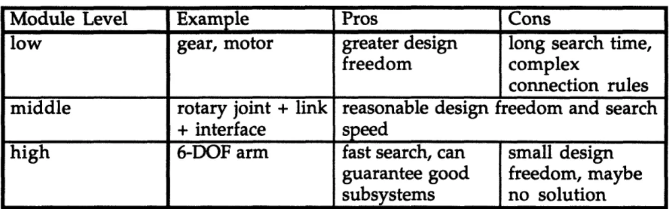
It has become clear at this point that a different level of modularity could be built into the algorithm, see Table 4. The modular parts inventory could be limbs or bodies (similar to subassemblies, above) instead of joints and links. Well-designed limbs and bodies would be developed before the search began. These then would be combined into robots, and everything before this step in Figure 9 would be eliminated. This would greatly reduce the assembly search space, and explicit rules could begin to be written for every combination, approaching an expert system robot designer. However, such and "expert system" will never produce an original robot. In this case, it was decided that predesigning subassemblies would unacceptably limit the variety of solutions. Modules could also be designed at the very low level of motors, gears, or even screws, but then the combinations rapidly increase, and the combination rules become exceedingly complex. The design space approaches the continuous space, and the advantages of modularity are lost.
Table 4. Module Levels. These are characteristic points on a continuous scale.
Module Level Example Pros Cons
low gear, motor greater design long search time,
freedom complex
connection rules
middle rotary joint + link reasonable design freedom and search
+ interface speed
high 6-DOF arm fast search, can small design
guarantee good freedom, maybe
subsystems no solution
In general, the lower the level of modules, the larger the search space, and the better the solution, but the longer the search will take. Solutions are better for lower level modules in general because they can be more finely tuned to a specific task. The level chosen for this design algorithm is therefore in "the middle," low enough to produce a wide variety of robots, but high enough to hide the very complex layer of fine details and allow simple combination
rules, and execute in a reasonable amount of time.
Search Method Comparison
Gradient
Traditional gradient-based search techniques [79] cannot be used for this search problem. The space of modular assemblies can be considered by definition non-continuous, and therefore no gradient exists. In a physical sense, this means that two robot assemblies that are extremely topologically "close," say only a single module is different, can have widely varying performance evaluations. No information about which robot to try next can be predicted via gradient methods.
Branch and bound
The quality of a branch and bound search is dependent on the accuracy of a guaranteed underestimator of robot performance [80]. For this application, because the performance is dependent on a hierarchical series of tests, a single simple and accurate performance underestimator is impossible. Branch and
bound searches might be performed on various subcomponents of the main search. This method might produce a better robot testing order. However, because of the hierarchical nature of the of the search, the "bounding" portion of the branch-and-bound technique would have to be designed to take this in to account.
Simulated annealing
Simulated annealing is a probabilistic process that traverses the solution space in a somewhat random manner [80]. This technique does not span the solution space, and does not guarantee optimality. Additionally, simulated annealing in general requires lengthy parameter tuning for convergence, and so is not appropriate for an automatic algorithm meant to cover a wide variety of circumstances (tasks, modules, rules, and evaluations.)
Genetic algorithms
Genetic algorithms by their nature identify good design components in
complex systems [81]. This leads to the concept of related robots - a highly
ranked robot is encouraged to have similar children, with the hope that some of them may be better than the parent.
Like simulated annealing, genetic algorithms do not guarantee an optimal robot. However, they do not require tuning and so might be used for the modular design problem. The filters, rules, and evaluations developed in this research can be applied to a genetic algorithm search as well; if the optimal robot is not required, then genetic algorithms might be a good search method to use for a faster solution.
Genetic algorithms might be incorporated into the hierarchical modular design algorithm in the following way. The search is conducted as before, except that when good robot assemblies are produced, some representation of them is added to a gene pool, see Figure 17. Good is defined as a high scoring assembly evaluation. There may be two gene pools, one for kits and one for
assemblies. Subsequent kits and assemblies are chosen via the genetic algorithm procedure, instead of in a regular order.
modules filters filters
(
assi filters ( eva desired robotFigure 17. Adding a genetic algorithm search Learning
The statistical learning process for designing the modular inventory described above could also be applied to more complex structures, such as subassemblies. Subassemblies that are used frequently could be remembered and tried first in future design searches. This would improve the average designs in a time-limited search.
Sensing, Control, and Communications
Robot parts such as sensors, communication devices, and control units are not presently included in this algorithm. These types of parts are generally decoupled from the structural design of the robot in a modular system. Because these modules are non-structural, and do not effect the topology of the robot, they can be added after the rest of the robot is built. For instance, if a robot needed to detect rot, a rot-detector sensor would be needed, independent how the robot was designed. The robot could be designed using
the search algorithm without the detector, and the detector would be added
after the solution was found. If the detector did affect the robot structure - if it
weighed a significant amount, for instance, then those features should be
factored into the robot design by including them as task requirements - a fixed