Compact and Low-Power Computational 3D Sensors for
Gestural Input
by
Andrea B. Colago
S.M., Massachusetts Institute of Technology (2010) B.E., Birla Institute of Technology and Science, Pilani (2007)
Submitted to the Program in Media Arts and Sciences, School of Architecture and Planning,
in partial fulfillment of the requirements for the degree of
Doctor of Philosophy in Media Arts and Sciences TCSSO at the
at the
UL 14
2014
MASSACHUSETTS INSTITUTE OF TECHNOLOGY
June 2014 LIBRARIES
@
2014 Massachusetts Institute of Technology. All rights reserved.Signature redacted
AuthorProgram in Media Arts and Sciences May 5, 2014
Signafure redacted.
Certified by Certified by Accepted by. Christopher M. Schmandt Principal Research Scientist Program in Media Arts and Sciences /, Thesj ApervisorSignature redacted
Vivek K Goyal Assistant Professor of Electrical and Computer Engineering Boston Univerisity Co-Supervisor
Signature redacted
Maes Associate Academic Head
Compact and Low-Power Computational 3D Sensors for Gestural Input by
Andrea B. Colago
Submitted to the Program in Media Arts and Sciences, School of Architecture and Planning,
on May 5, 2014, in partial fulfillment of the requirements for the degree of
Doctor of Philosophy in Media Arts and Sciences
Abstract
Mobile devices have evolved into powerful computing platforms. As computing capabilities grow and size shrinks, the most pronounced limitation with mobile devices is display size. With the adoption of touch as the de facto input, the mobile screen doubles as a display and an input device. Touchscreen interfaces have several limitations: the act of touching the screen occludes the display, interface elements like on-screen keyboards consume precious display real estate, and navigation through content often requires repeated actions like pinch-and-zoom. This thesis is motivated by these inherent limitations of using touch input to interact with mobile devices. Thus, the primary focus of this thesis is on using the space around the device for touchless gestural input to devices with small or no displays. Capturing gestural input in this volume requires localization of the human hand in 3D. We present a real-time system for doing so as a culmination of an exploration of novel methods for 3D capture. First, two related systems for 3D imaging are presented, both relying on modeling and algorithms from parametric sampling theory and compressed sensing. Then, a separate system for 3D localization, without full 3D imaging, is presented. This system, Mime, is built using standard, low-cost opto-electronic components - a single LED and three baseline separated photodiodes. We demonstrate fast and accurate 3D motion tracking at low power enabled by parametric scene response modeling. We combine this low-power 3D tracking with RGB image-based computer vision algorithms for finer gestural control. We demonstrate a variety of application scenarios developed using our sensor, including 3D spatial input using close-range gestures, gaming, on-the-move interaction, and operation in cluttered environments and in broad daylight conditions.
Thesis Supervisor: Christopher M. Schmandt
Title: Principal Research Scientist, Program in Media Arts and Sciences
Thesis Co-Supervisor: Vivek K Goyal
Compact and Low-Power Computational 3D Sensors for Gestural Input
by
Andrea B. Colago
The following people served as readers for this thesis:
Signature redacted
Thesis Reader
Joseph A. Paradiso
Associate Professor of Media Arts and Sciences
Program in Media Arts and Sciences
Acknowledgements
I had an incredible experience during my doctoral studies at MIT. At times, close to six years in graduate school felt like a lifetime. But as I wrote this thesis, it all seems to have happened too quickly. Getting to this point has been made possible by many wonderful and talented people around me and I would like to take a few lines to express my sincere gratitude to them.
To my advisor Chris Schmandt for giving me an opportunity to attend graduate school at MIT by accepting me to his group twice - in 2008 for the Master program and then again in 2010 for doctoral studies. I am grateful to him for his support, encouragement and openness to new areas of research; but most importantly for the confidence he has in his students. To Vivek Goyal for taking a chance at collaborating with me when I was very early in the PhD, and for co-supervising my thesis. I would like to thank him for the time he spent providing feedback on my work and for imparting his rigor in technical writing and presenting. To Joseph Paradiso, for the inspiration his work and classes have been. I have been fortunate to have worked with him as part of the Design and Innovation workshops in India where I was inspired by his engagement with problems that are socially
and economically unique to India.
To my colleagues at the Speech+Mobility group at the Media Lab for their support and for contributing to many good times. Special thanks to Jaewoo Chung, Drew Harry, Charlie DeTar, Misha Sra, Sujoy Chowdhury and Cindy Kao.
To my collaborators for their great spirit toward team work - Ahmed Kirmani, Hye Soo Yang, Dongeek Shin, Dr. Franco Wong and Dheera Venkatraman. I had a multiplicative
learning factor due to the orthogonal expertise they brought to the team effort.
To Professors Jeffrey Shapiro and Alan Oppenheim whose classes and first-principle ap-proach to problem formulation and solving have made a lasting impact on how I look at new problems.
To the larger MIT community for opportunities to explore entrepreneurship.
Finally, to my parents and brother for believing in my dreams, and to the memory of my grandmother, Lavita Braz, who was the bravest person I knew.
Contents
Abstract 3
Acknowledgements 7
1 Introduction 13
1.1 Around-device input ... ... 15
1.1.1 On-body and close-to-body interaction . . . . 15
1.1.2 Proximal surfaces for around-device interaction . . . . 17
1.1.3 M icro-movements . . . . 18
1.2 Technical challenges and sensing constraints . . . . 18
1.3 Thesis theme and outline . . . . 19
2 Background 23 2.1 Time of flight principles for active 3D sensing . . . . 24
2.2 Sparsity and compressed sensing . . . . 25
2.2.1 Challenges in exploiting sparsity in range acquisition . . . . 25
2.2.2 Compressive LIDAR . . . . 26
2.3 Parametric optical signal processing . . . . 27
2.4 Optical imaging systems for capturing hand gestures . . . . 28
2.4.1 Gestural control with 2D cameras . . . . 29
2.4.2 NIR Intensity Based Techniques . . . . 30
2.4.3 TOF Based Techniques . . . . 31
2.5 Non-camera based techniques for capturing hand gestures . . . . 32
2.5.1 Sound based 3D Source Localization . . . . 33
2.5.2 Magnetic field based sensing . . . . 33
2.5.3 Electric field sensing . . . . 34
2.5.4 Capacitive sensing . . . . 35
2.5.5 W i-fi based sensing . . . . 36
3 Compressive Depth Acquisition Camera 37 3.1 Notation and assumptions for analysis of a single rectangular facet . . . . . 40
3.2 Response of a single rectangular facet to fully-transparent SLM pattern . . 42
3.2.1 Scene response. . . . . 42
3.2.2 Parameter recovery . . . . 46
3.3.1 N otation . . . . 3.3.2 Scene response. . . . . 3.3.3 Sampled data and Fourier-domain representation . 3.3.4 Algorithms for depth map reconstruction . . . . . 3.4 Depth map acquisition for general scenes . . . . 3.4.1 General planar shapes . . . . 3.4.2 Multiple planar facets . . . . 3.5 Experim ents . . . . 3.5.1 Imaging setup and measurement . . . . 3.5.2 Depth map reconstruction results . . . . 3.6 Discussion and extensions . . . . 3.6.1 Scenes with non-uniform texture and reflectance . 3.6.2 Use of non-impulsive illumination sources . . . . . 4 Compressive Depth Acquisition Using Single Photon
4.1 Imaging setup and data acquisition . . . . 4.2 Signal modeling and depth map reconstruction . . . . 4.2.1 Parametric response of fronto-parallel facets . . 4.2.2 Shape and transverse position recovery . . . . . 4.2.3 Depth map reconstruction . . . . 4.3 Experimental results . . . . 4.4 Sum m ary . . . . 4.4.1 Lim itations . . . .
5 Mime: Low-Power Mobile 3D Sensing
5.1 Design considerations . . . . 5.2 Technical overview and comparison . . . . 5.2.1 Operation and assumptions . . . . 5.2.2 Key technical distinctions . . . . 5.2.3 Comparisons with Mime . . . . 5.3 Mime time-of-flight module for 3D hand localization . 5.4 Region of interest RGB-image processing . . . . 5.5 Hardware implementation . . . . 5.5.1 Calibration . . . . 5.6 Performance evaluation . . . . 5.7 Gesture sensing using Mime . . . . 5.8 Lim itations . . . . Counting Detectors 67 . . . . 68 . . . . 70 . . . . 70 . . . . 72 . . . . 73 . . . . 75 . . . . 78 . . . . 79 81 82 84 85 86 88 88 93 94 95 96 98 99 6 Theoretical Extensions for Tracking Multiple Planar Objects 6.1 Imaging Setup and Signal Models . . . . 6.1.1 Two Hands . . . . 6.1.2 Planar Scene . . . . 6.1.3 Sampling the Scene Response . . . . 6.2 Scene Feature Estimation . . . . 6.2.1 Two Hands . . . . . . . . 47 . . . . 48 . . . . 50 . . . . 53 . . . . 56 . . . . 56 . . . . 57 . . . . 59 . . . . 59 . . . . 61 . . . . 63 . . . . 64 . . . . 65 103 104 105 106 107 108 109
6.2.2 Planar Scene . . . . 110
6.3 Simulations . . . . 111
6.3.1 Discussion . . . . 112
7 Applications and Interaction Techniques 115 7.1 Input using our hands . . . . 117
7.1.1 Pointing gesture . . . . 117
7.1.2 Shape-based gestures . . . . 118
7.1.3 Supplementary modalities . . . . 119
7.2 Interaction techniques with head mounted displays . . . . 120
7.3 Applications with the Google Glass . . . . 124
7.3.1 System design. . . . ... 125
7.3.2 Live trace . . . . 126
7.3.3 Live filters. . . . . 128
7.3.4 Text annotations . . . . 129
7.4 Back to the desktop . . . . 131
Chapter 1
Introduction
Anyone who has used mobile devices understands the broad set of functions they support. Their ubiquity makes them ideal for communication, scheduling, entertainment, data cap-ture, and retrieval on the go. Early mobile devices were characterized by tangible keypads and small displays. However, their form factor has been in a state of constant flux in an attempt to support their expanding functionality. They are now available in the form of wrist-worn and head-mounted devices in an effort to make interaction more seamless. Simultaneously, interaction has also evolved to more natural forms like voice and touch. Additionally, mobile devices have extended our perception of the physical world through virtual and visible augmented reality.
We are embracing the digital future of ubiquitous computing envisioned by Mark Weiser [1], "The most profound technologies are those that disappear. They weave themselves into the fabric of everyday life until they are indistinguishable from it." Toward this vision we continue to explore natural input, output and feedback mechanisms for our mobile and wearable devices. Currently, smart phones and tablets have a distinctive flat touch-based interactive glass screen. These devices satisfy to a large extent our always-on computing requirements on the go. The natural next step is to think about truly weaving input, output and feedback subtly. This vision for ubiquitous human computer interaction has recently surfaced again, this time with higher fidelity head-mounted wearable displays and smart
watches with a smart phone or tablet providing the bulk of the computing capabilities. For a seamless experience between external computing and new form-factors of wearables, we are tasked with transitioning input from the domain of well understood keyboard, mouse and touch to meaningful synergetic forms for wearables.
Currently, touch-screen input is the primary interaction modality for smart devices which require a display -no matter how small. For wearables, such as head-mounted displays, voice is the input of choice; these upcoming devices do not have an touch-screen display which can double as an input device. Touch input on high fidelity displays elegantly merges input, output and visual feedback at the point of contact. However, flat screen touch interfaces do not fully take advantage of human dexterity and have their own set of limitations:
" the act of touching requires the user to be in constant contact with the device;
" touching the screen for input occludes the display;
" even simple tasks like menu navigation require tedious, repetitive actions; and
* accurate target acquisition is a challenge when the surface area of a finger is larger than supported (aptly described as the fat finger problem).
When touch surface shrinks, equipping users with better input tools for more complex and visually demanding tasks will be important in enabling new applications and making the interaction experience of the unit more intuitive and efficient.
In this thesis, we focus on capturing input around the mobile or wearable device. The space around the device is typically free, uncluttered and close enough to the device to provide line of sight if required by any sensing system. We focus on hand gesture input in the proximal space around the device as a natural way of moving beyond touch to free-space. By sensing off-screen input through gestures, this approach conserves display space that would ordinarily get consumed by touch input itself.
1.1
Around-device input
The use of gestures for human-computer interaction is an active research area. From a user experience viewpoint, gestural control using 3D cameras has been demonstrated to be an intuitive, robust, and widely-popular input mechanism in gaming applications.1 New input technologies, like the Leap Motion Controller [2] and compact time-of-flight (TOF) cameras [3, 4], are still being explored for gesture-controlled interfaces in the context of personal computing spaces. Recent user studies have demonstrated that 3D gesture input is at least as effective as touch input for mobile devices [5]. In addition to input implications for smartphones, this finding raises interesting possibilities for smart wearables, like head-mounted displays (HMD), which lack a dominant input interface like touch.
Around-device interaction can be captured in different physical spaces around the mobile device. This could be the space in the immediate proximity of the device or input locations that are not within line-of-sight but create opportunities for around device-like input and interaction. Broadly, we categorize these interactions spaces as three different regions. This categorization of previously explored around-device interaction methods is presented in Fig. 1-1.
1.1.1 On-body and close-to-body interaction
An opportunistic space in the immediate proximity of personal devices is the body surface itself, which can often be available for input. The gesture pendant [6] is a very early example of gesture recognition in the space around a wearable device. More recently, researchers have examined the design of on-body and close-to-body gestural interfaces using optical imaging sensors 2D/3D cameras mounted in different regions close to the user; Omnitouch [7] mounts the 3D camera on the shoulder of the user, and Shoesense [8] mounts a 3D camera on a user's shoe facing up. Often these interactions necessitate appropriating the body surface for displaying interface elements. In the above examples as well as in examples like Wear-ur-world (WUW) [9] and LightGuide [10], body worn projectors and projectors mounted in the
on body wear-ur-woria (2uug) Mistry et al, [9] on external surfaces Sidesignt (2Ub) Butler et al. [17] micro-movements Nenya (2011) Ashbrook et al. [20] SideBySide (2011 Willin At alA 118 uTrack (h- -t bKinpui kluIu) Harrison et al. [11] onauuwruppets ku Cowan et al. [15]
Figure 1-1: Categories of around-device interaction. On and close-to body interactions that use the body surface for a combination of input and visual feedback (left). On external surface interaction which uses surfaces like table-tops and walls around the device (middle). Micro-movements that off-load interaction without requiring much visual distraction (right).
environment respectively provide visual cues to the user. The user primarily manipulates these projected elements through the use of hand movements and gestures. Capturing hand movements or touch-like finger input on the body surface extend to non-optical sensing systems. For example, Skinput [11] senses these signals directly through bio-acoustic sensing of muscle movements. On-body interfaces have also been implemented through distributed sensors on clothing - as seen in Second Skin [12] - which capture body motion with actuated feedback for motor learning. Another class of examples [13,14] instrument the environment with motion capture systems such as the Vicon to create applications that track free-form hand movement, position, and orientation. Imaginary interfaces [13] uses close-to-body hands movements without the use of visual or haptic feedback with the premise that part of the interface resides in the user's imagination. This interaction technique offloads visual feedback requirements to the user's spatial memory. In a related piece, Chen et al. [14]
Digits (2012) Kim et al [22]
input actions. Their work shows proximal interactions through body shortcuts.
1.1.2 Proximal surfaces for around-device interaction
The space around the user often has surfaces that may be available for capturing free-form hand gestures as input without using traditional interaction tools like touch, styli, keyboards and mice. Typically, these include surfaces like walls, tabletops and sometimes physical objects surrounding the user. Often such surfaces are uncluttered or ideal for feedback using projection mechanisms to present visual information. Input is then captured through hand movements in front of such projections. An illustrative example in this case is ShadowPuppets [15], in which the mobile screen interface is projected on to a surface around the user; the user then interacts through hand gestures. Placing the hand in front of the projector casts a shadow of the gesture on the surface, which is then captured by an optical imager. The detected gesture manipulates the projected interface. Another similar interaction scenario for multiple users is demonstrated in SideBySide [16]. Opportunistically projecting on objects and surfaces has the advantage of being able to provide a shared visual space for multiple users. Projecting on everyday real-world objects was also explored in [9]. Horizontal surfaces are also ideal for ADI while using the mobile device screen as output. Hand movements, like tapping on the surface, are captured as input, and relevant output is displayed on the mobile screen. SideSight [17], for example, captures input on both sides of the mobile device using infrared (IR) proximity sensors and tracks multiple fingers. The system comprises pairs of IR emitters and photodiodes that detect the presence of fingers. The use of a 1-D array of these emitter-receiver pairs offers coarse spatial (1-D) granularity of input as well as depth (distance to the array or proximity). Feedback to the user is provided through the display of the mobile device and is application dependent. A related example using a similar sensing approach is seen in HoverFlow [18], where ADI is explored above the device.
1.1.3 Micro-movements
Remote input through subtle finger and wrist movements to a device is another way of off-loading interactions from small touch screen displays. This style of interaction requires wrist worn sensors instead of sensors mounted on the mobile device itself. Finger-worn rings demonstrated by Bainbridge and Paradiso in [19], the system Nenya [20] and uTrack [21] provide input mechanisms without requiring visual attention in the direction of input. Both these interaction techniques are enabled by magnetic field sensing to determine finger move-ments. uTrack provides mouse pointer-like movement just by minor finger movements, while Nenya maps rotation of the ring itself to navigate interface elements. In another hand-worn implementation, the authors of Digits [22] propose using all fingers in a single-handed inter-action to control interface elements without distrinter-action of visual attention; a similar system has been recently implemented and evaluated by Way and Paradiso in [23]. While the above interactions are subtle and require minimal visual attention, they require instrumenting the user with sensors, which could possibly encumber the experience.
1.2
Technical challenges and sensing constraints
The review of around-device interaction in the previous section reveals important benefits of extending input space for devices constrained by touch display size. The space around the device is unused and often unoccluded. Close-range 3D gesture sensing introduces a new in-teraction paradigm that goes beyond touch and alleviates its current limitations. Examples in our review reveal new interaction techniques that may be adapted to emerging wearable devices. However, the review also points to existing challenges with sensing such input. The implementation of 3D gestural input requires integration of depth sensors in mobile and wearable devices. However, existing state-of-the-art 3D sensors cannot be embedded in mobile platforms because of their prohibitive power requirements, bulky form factor, and hardware footprint. Wearing additional sensors on the body possibly creates user encum-berance while sensing input. These challenges demonstrate the need for unencumbered 3D gesture sensing in scenarios where the user is mobile. The limitations of conventional input
technologies warrant development of new sensors for intuitive and effective free-form gestu-ral input, corroborating our vision for building sensors that can eventually be embedded in mobile and wearable devices.
Design considerations: An input technology intended for around-device input and inter-action with mobile or wearable devices should ideally possess the following characteristics:
" Technical: High accuracy, low power, low latency, small size, daylight insensitivity, and robust performance in cluttered, noisy and fast-changing environments.
" User experience: Interacting with the mobile device should be intuitive and should not induce fatigue upon prolonged use. The input device must be able to support both motion- and position-controlled gestures in 2D and 3D.
" User convenience: The sensor should be embedded within the mobile device to enable unencumbered user interaction. The user should not be required to wear markers [24] or external sensors like wrist worn trackers [22, 25] or carry additional touch pads.
1.3
Thesis theme and outline
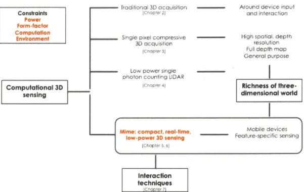
This thesis presents research on new 3D capture techniques that enable around-device in-put for mobile and wearable devices, satisfying the design considerations outlined in the previous section. The goal of this work is to capture the richness of the three-dimensional world through novel computational 3D sensing frameworks that could lead to new input and interaction opportunities. The process involved exploring, designing and building several different measurement and processing frameworks in an effort to resolve technical con-straints of existing 3D sensors - power, form-factor (size), computation requirements, and performance in diverse environmental conditions - by exploiting the physics of light trans-port. The latter part of the thesis focused on integrating these sensing approaches with mobile devices like smartphones and head-mounted displays. Fig. 1-2 shows a snapshot of the overarching research goal and different approaches covered.
Traditional 3D acquisition Ichapter il
Single pixel compressive
-3D acquisition
lChrpler 3)
Low power single photon counting LIDAR
:hcipler 4j
Mime: compact, real-time' low-power 3D sensing
[ChOPte 5. 6]
Around device input and interaction
High spatial, depth resolution Full depth map General purpose Richness of three-dimensional world Mobile devices Feature-specific sensing Interaction techniques CnaEe 7
Figure 1-2: Thesis theme and outline. This thesis has focused on capturing the richness of our 3D world through the use of computational 3D sensing to create new interaction techniques with mobile devices. We have explored new 3D acquisition techniques to meet the constraints mobile devices present. The main focus of this dissertation is Mime, a compact, low-power 3D sensor and its real-time use in applications for mobile devices.
Chapter 2 reviews existing sensing techniques. The rest of this thesis then describes each of the novel imaging techniques in detail. Our first exploration involved reducing the size of 3D sensors to a single pixel. To achieve this, we introduce the framework for compressively acquiring 3D information using spatio-temporal modulation of active illumination discussed in Chapter 3 and [26]. Next, we investigated lowering power requirements for active 3D im-agers, resulting in the methods in Chapter 4 and [27]. Here, we combined savings in size from the compressive depth acquisition framework with a low-power implementation enabled by a very sensitive single-photon avalanche photodiode (SPAD). However, these techniques do not address mobile-friendly computation requirements. Additionally, for tractable compu-tation the overall system bandwidth of the imaging components should be within mobile processor capabilities. This makes the acquisition problem even more challenging because
Constraints Power Form-factor Computation Environment Computational 3D sensing
the choice of sensing elements and illumination sources is limited to low-bandwidth compo-nents. The advantage of low bandwidth components is their low cost and ease of fabrication. For the purpose of the thesis, we focus only on addressing mobile technical constraints. The culmination of our 3D acquisition frameworks is a low-power, compact, precise and real-time operating sensor, Mime, which is the main contribution of the thesis, presented in Chapter 5 and [28]. This sensor was designed to resolve constraints that previous systems did not address while benefitting from the trade-off insights observed through the design and experiments with previous systems. Chapter 6 and [29] present theoretical extensions of the sensing framework for acquiring multiple hands as well as generic planar surfaces. Chapter 7 focuses on designing and building new interaction and input experiences with the real-time operating Mime sensor. We present two specific styles of user scenarios, one with the device mounted on a head-mounted display (in our case Google Glass2) and the other with a device mounted on a smartphone which makes the surface next to the display an immediate input canvas. We discuss the trade-offs and implications of the acquisition techniques presented in this thesis in Chapter 8 and point to future extensions.
2
Chapter 2
Background
This chapter reviews prior work on optical 3D acquisition techniques that this thesis builds upon. We discuss application-specific sensing, in our case human hand gesture sensing and introduce alternate methods that capture hand gestures without traditional imaging.
Three main technical areas are central to understanding the computational sensors presented in this thesis:
" Time-of-flight (TOF) based active 3D sensing
* Compressed sensing
" Parametric optical signal processing
These areas will be discussed in Sections 2.1, 2.2 and 2.3. Through the use of the compu-tational sensors presented in this thesis, we are interested in enabling gesture-based around device input for mobile devices - handheld smart phones and wearables; related systems for
2.1
Time of flight principles for active 3D sensing
Sensing 3D scene structure is an integral part of applications ranging from 3D microscopy [30] to geographical surveying [31]. While 2D imaging is a mature technology, 3D acquisition techniques have room for significant improvements in spatial resolution, range accuracy, and cost effectiveness. Humans use both monocular cues - such as motion parallax - and binocular cues - such as stereo disparity - to perceive depth, but camera-based stereo vi-sion techniques [32] suffer from poor range resolution and high sensitivity to noise [33,34]. Computer vision techniques - including structured-light scanning, from-focus, depth-from-shape, and depth-from-motion [32,35,36] - are computation intensive, and the range output from these methods is highly prone to errors from miscalibration, absence of suffi-cient scene texture, and low signal-to-noise ratio (SNR) [33,34,36].
In comparison, active range acquisition systems such as LIDAR systems [37] and TOF cameras [38,39] are more robust against noise [34], work in real-time at video frame rates, and acquire range information from a single viewpoint with little dependence on scene reflectance or texture. Both LIDAR and TOF cameras operate by measuring the time difference of arrival between a transmitted pulse and the scene reflection. LIDAR systems consist of a pulsed illumination source such as a laser, a mechanical 2D laser scanning unit, and a single time-resolved photodetector or avalanche photodiode [37,40,41]. The TOF camera illumination unit is composed of an array of omnidirectional, modulated, infrared light emitting diodes (LEDs) [38,39,42]. The reflected light from the scene - with time delay proportional to distance - is focused at a 2D array of TOF range sensing pixels. Localization in 3D by the TOF principle could also be performed without optics by exploiting ultra-wide band (UWB) impulse radios which detect TOF of reflected RF impulses [43]. The resolution provided by such systems often tends to be the limiting factor in their adoption. A major shortcoming of LIDAR systems and TOF cameras is low spatial resolution, or the inability to resolve sharp spatial features in the scene. For real-time operability LIDAR devices have low 2D scanning resolution. Similarly, due to limitations in the 2D TOF sensor array fabrication process and readout rates, the number of pixels in TOF camera sensors is typically lower than most 2D RGB cameras [42]. Consequently, it is desirable to develop
novel, real-time range sensors that possess high spatial resolution without increasing the device cost and complexity.
2.2
Sparsity and compressed sensing
Many natural signals can be represented or approximated well using a small number of nonzero parameters. This property is known as sparsity and has been widely exploited for signal estimation and compression [44]. Making changes in signal acquisition architectures - often including some form of randomization - inspired by the ability to effectively exploit sparsity in estimation has been termed compressed sensing (CS). CS provides techniques to estimate a signal vector x from linear measurements of the form y = Ax
+
w, where wis additive noise and vector y has fewer entries than x. The estimation methods exploit that there is a linear transformation T such that Tx is approximately sparse. An early instantiation of CS in an imaging context was the "single-pixel camera" [45, 46] which demonstrated the use of pseudorandom binary spatial light modulator (SLM) configurations for acquiring spatial information and exploitated transform-domain sparsity.
The depth map of a scene is generally more compressible or sparse than the reflectance or texture (see Fig. 2-1). Thus, we expect a smaller number of measurements to suffice; this is indeed the case, as our number of measurements is 1 to 5% of the number of pixels as compared to 10 to 40% for reflectance imaging [45,46].
2.2.1 Challenges in exploiting sparsity in range acquisition
In TOF systems, depths are revealed through phase offsets between the illumination signal and the reflected light rather than by direct measurement of time delays. These mea-surements are made either by raster scanning every point of interest in the field of view or establishing a correspondence between each spatial point and an array of sensors. Compres-sively acquiring range information using only a single detector poses two major challenges. First, the quantity of interest - depth - is embedded in the reflected signal as a time shift.
10 -image depth map 10, c 10 E 0 2 4 6 8 10 12 4 Coefficient index x 10
Figure 2-1: Sparsity of a signal (having a basis expansion or similar representation with a small number of coefficients significantly different from zero) is widely exploited for signal estimation and compression [44]. An N x N-pixel digital photograph (A) or depth map (B) of a scene requires N2 pixel values for representation in the spatial domain. As illustrated with the output of an edge-detection method, the Laplacian of a depth map (D) typically has fewer significant coefficients than the Laplacian of a photograph (C). This structure of natural scenes is also reflected in discrete wavelet transform (DWT) coefficients sorted by magnitude: a photograph has slower decay of DWT coefficients and more nonzero coeffi-cients (E: blue, dashed) than the corresponding depth map (E: green, solid). We exploit this simplicity of depth maps in our range acquisition framework.
The measured signal at the detector is a sum of all reflected returns and hence does not directly measure this time shift. This nonlinearity worsens when there are multiple time shifts in the returned signal corresponding to the presence of many depths. Varying the SLM configuration would produce different nonlinear mixtures of depths and thus could make the solution unique, but the complexity stemming from nonlinearity of mixing remains. The second challenge comes from the fact that a single detector loses all directionality information about the reflected signals; this is present in reflectance imaging as well.
2.2.2 Compressive LIDAR
In a preliminary application of the CS framework to range acquisition in LIDAR sys-tems [47], 2 ns square pulses from a function generator drive a 780 nm laser diode to illuminate a scene. Reflected light is focused onto a digital micromirror device (DMD) that implements pseudorandomly-chosen binary patterns. Light from the sensing patterns is re-ceived at a photon-counting detector and gated to collect photons arriving from an a priori
chosen range interval, and then conventional CS reconstruction is applied to recover an image of the objects within the selected depth interval. The use of impulsive illumination and range gating make this a conventional CS problem in that the quantities of interest (reflectances as a function of spatial position, within a depth range) are combined linearly in the measurements. Hence, while this approach unmixes spatial correspondences it does not directly solve the aforementioned challenge of resolving nonlinearly-embedded depth information. The need for accurate range intervals of interest prior to reconstruction is one of the major disadvantages of this system. It also follows that there is no method to distinguish between objects at different depths within a chosen range interval. Moreover, acquiring a complete scene depth map requires a full range sweep. The proof-of-concept system [47] has 60 cm range resolution and 64 x 64 pixel resolution.
2.3
Parametric optical signal processing
Analog signals in the real world typically contain rich information and have variable band-widths. Utilization of these signals routinely requires access to digital versions of these signals without losing fidelity during the conversion. Classical sampling theory necessitates sampling above the Nyquist rate. For a signal whose maximum frequency is fmax, this rate would be 2frnax. Sampling above the Nyquist rate ensures that the original analog signal is preserved and usable. For higher bandwidth signals, sampling at the Nyquist rate would require very fast sampling.
However, some classes of high bandwidth signals that appear in several practical applica-tions, can be completely described by a small number of parameters. Examples include short pulse trains in medical imaging, radar and ultra-wideband systems. In the pulse train example, these parameters would be the time-delay between pulses and their amplitudes. These two parameters completely describe this example signal of interest. Even though the Fourier bandwidth of an impulse function (the closest representation of a very short pulse) is infinite, we can see how it may be wasteful to sample this pulse train at its Nyquist rate if it can be uniquely described by only two parameters. Of course, we would need to
recover these two parameters for each pulse in the train. This brings us to an important condition - within any finite time segment of length
r,
the signal is completely described by no more than K parameters. This is the local rate of innovation of the signal which is no more than K degrees of freedom every r seconds. A signal is said to have a finite rate of innovation (FRI) if it can be described by a finite or small number of parameters per unit time [48]. The recently proposed finite rate innovation (FRI) framework solves the problem of recovering these signal parameters from discrete samples of a filtered version of the signal of interest, as long as the number of samples is at least twice the number of parameters. This proves to be a powerful tool to recover a relatively high bandwidth signal at a much lower sampling rate.The problem of recovering delays corresponding to depth of scene objects in the time-of-flight setup is analogous to the pulse train example we just discussed. Further, we also know that depth is a naturally sparse signal which supplements the requirement of a small number of parameters in the reflected signal of interest. This problem was not previously explored in the context of optical signals. Most time-of-flight sensors are inherently ban-dlimited. The sensor thus provides access to a lowpass filtered version of the time-of-flight pulses.
2.4
Optical imaging systems for capturing hand gestures
Sensing human hand gestures requires some form of sensing the human hand. For the pur-pose of this thesis, we define hand gestures as coordinated spatial and temporal movements that are either captured at a single point in time or over a period of time. Therefore, hand gesture capture could require capturing hand movement independent of shape or hand mo-tion along with addimo-tional informamo-tion such as pose. This thesis considers hand momo-tion with and without shape dependence. In this chapter, we will discuss techniques, sensors and sys-tems designed to recover the continuum from rigid hand motion to hand shape and motion coordinated over time. From a design perspective, only motion-based gesture activation has a broader set solutions that could reside outside of line of sight of target hand; in this
category we discuss sensing systems either present in the environment or mounted on the target, such as magnetic field based sensing, electric field based sensing, ultrasound based sensing as well as bio-acoustic signal sensing of the target hand. Shape recovery however requires direct line of sight with the target hand. Typically, optical imaging is a popular choice for recovering hand shape together with motion.
In this section, we review techniques sensing hand motion and shape. We will highlight key considerations which determine suitability of these techniques to mobile device constraints. Our goal through this exposition is to identify how the theoretical framework of signal mod-eling and the practical considerations in the implementation of Mime overcome challenges in previously developed systems.
The three main techniques for depth sensing are stereo disparity-based methods from com-puter vision [36], and active illumination techniques which are further categorized as near infrared (NIR) intensity-based methods, and sensors that operate on the TOF principle. Stereo disparity-based techniques are passive in the sense that they use natural light or ambient illumination. On the other hand, active optical methods use specialized NIR light sources for scene illumination. Compared with passive stereo vision, active optical meth-ods have proven to be more robust and reliable for a variety of industrial, consumer and scientific applications [34], [49], [50]. Here we present a short survey of of these techniques and compare them with Mime on the aforementioned performance metrics and resource constraints.
2.4.1 Gestural control with 2D cameras
Computer vision techniques allow the use of embedded 2D cameras to recognize hand ges-tures [51]. These gesges-tures have been widely used for unencumbered line-of-sight interaction with mobile devices. Standard RGB image-based gesture recognition suffers from several technical problems: it has poor resolution and is not robust in cluttered environments, it is computationally complex for mobile processors, and it supports only a small dictionary of simple motion-cued gestures like waving. RGB image-based gesture recognition can be
made more precise, robust and generic at the expense of using of additional elements like color markers or infrared trackers [6].
2.4.2 NIR Intensity Based Techniques
The three main NIR image intensity based techniques are active stereo vision, speckle pattern decorrelation, and infrared proximity array sensing. All of these methods require illuminating the scene with an always on light pattern which is the major source of power consumption in these sensors.
Active stereo vision involves illuminating the scene with a structured light pattern and imaging with two baseline-separated cameras [52]. The illumination patterns provides rich scene texture which is necessary to create a dense stereo-correspondence and thereby depth maps that do not contain artifacts such as holes in scene regions with insufficient texture -a common problem with p-assive stereo disp-arity im-aging.
Speckle pattern decorrelation uses a laser source to project a speckle or dot pattern on the scene. The dot pattern on the scene is imaged using a single NIR camera. The capture images is processed using a local cross-correlation method called region-growing random dot matching algorithm to detect and assign depth labels to the laser speckles [53].
Infrared Proximity Array (IPA) sensors operate on the fact that closer objects appear brighter under active illumination. The scene is illuminated using two light sources with different characteristics (intensity and half-angle) and two separate NIR intensity images are recorded. Scene depth at every pixel is computed using a pre-computed polynomial regression curve that relates the intensity ratio between the two NIR images with scene depth point [54].
Despite the advantages that active NIR intensity based method have over conventional stereo vision in imaging quality and depth resolution, they require high optical output because the light source is always on and it needs to be stronger than ambient illumination in order for the technique to be effective. As a result active NIR intensity based depth
sensors are also sensitive to ambient light. Also their depth accuracy and range resolution performance are baseline limited. Moreover, these sensors are found to perform poorly at close working ranges of under 1 meter.
2.4.3 TOF Based Techniques
TOF depth sensors operate by flood illuminating the scene using an intensity modulated light source and focusing the reflected light on to a 2D array of special sensors which computes the distance to a scene point by measuring the time delay or phase shift caused due to the back and forth propagation of light. There are three major types of TOF depth sensors, amplitude modulated cosine wave (AMCW), light detection and ranging (LIDAR) systems and short pulsed TOF systems with time-gated sensors.
AMCW TOF cameras flood illuminate the scene with an omnidirectional NIR light pulse. Typically, the transmitted pulse is a modulated square wave with a pulse repetition fre-quency (PRF) of 10 MHz or higher and a 50% duty cycle. This implies that the light source is on half the time. The reflected light is converted to an electrical signal by the CMOS sensor pixels which is then correlated with a cosine wave of the same frequency as the modulation frequency of the light source [38]. Four samples of the cross correlation function are used to compute the amplitude, background intensity and the phase shift of the received waveform relative to the transmitted pulse. This phase shift measured at each pixel is directly proportional to scene depth.
Time-gated TOF systems also operate using flood NIR illumination but using a much shorter pulse (50% duty cycle at a high PRF of 50 MHz) [55], [56]. The image sensor has a fast gating mechanism based on an electro-optic Gallium-Arsenide shutter. The amount of pulse signal collected at pixel corresponds to where within the depth range the pulse was reflected from, and can thus be used to calculate the distance to a corresponding point on the captured subject.
LIDAR systems measure scene distance by raster scanning the scene with a short pulsed laser source [37]. The pulse widths are typically in the sub-nanosecond range with a PRF
of 1 - 2 MHz. The sensor is single photon counting detector which time-stamps the arrival of every detected photon with picosecond accuracy. For every raster position, the photons are collected over a small time-interval. The peak position of the histogram computed using the photon arrival times is the depth estimate.
TOF depth sensors offer several advantages over active NIR intensity based techniques for depth measurement. They have higher depth accuracy and range resolution, and operate from a single viewpoint with no baseline restrictions. AMCW TOF cameras have ambient light rejection mechanisms [4] making them less sensitive to ambient light. Despite the im-provement in imaging quality by TOF cameras, they come with their own set of limitations. Due to the fast timing requirements, TOF sensors use custom hardware for illumination and sensing which is often difficult to manufacture and leads to expensive cost. The spa-tial or lateral resolution of TOF cameras is lower than that of NIR intensity based depth sensors [26]. In contrast, NIR intensity based depth cameras use standard CMOS arrays and NIR light sources for scene illumination and also are priced at a significantly lower cost. TOF depth cameras also have to account for additional imaging artifacts like distance aliasing or phase wrapping, and multipath distortion which are absent in NIR intensity based cameras.
2.5
Non-camera based techniques for capturing hand
ges-tures
In this section we review motion-based gestural control enabled by techniques that do not use any image formation. Non-camera based techniques offer advantages in power consumption and distance of operation. However, these techniques typically do not disambiguate hand shapes and often provide lower accuracy tracking compared with their optical imaging counterparts.
2.5.1 Sound based 3D Source Localization
In addition to optical methods for distance sensing, ultrasound based transducers are also frequently used in robotics for 3D object localization [57]. More recently, they have been incorporated into human computer interfaces for hand and gesture tracking [58],
[59].
A typical setup involves transmitting an omni-directional ultrasound beam towards the scene and using a linear array of microphones to accomplish 3D source localization using beam-forming and time-delay of arrival estimation [57]. Another implementation Soundwave [60] uses the speaker and microphone that are already present in most devices to sense in-air gestures around such devices. The system generates an inaudible tone and uses the doppler (frequency) shift that is produced when the tone gets reflected by moving objects such as hands.State-of-the-art ultrasound systems are less precise at a centimeter or worse range resolu-tion, compared with their optical counterparts which offer sub-centimeter depth resolution. Also ultrasound transducers do not produce full scene depth maps and perform poorly in localizing multiple objects. Their performance also degrades significantly in cluttered nat-ural scenes and reverberant environments due to strong multiple scattering of sound waves. In contrast, light undergoes diffuse scattering in most natural scenes which does not mar the imaging quality of active optical depth sensors as much.
2.5.2 Magnetic field based sensing
Sensing motion based on movement of a magnet-marker has been implemented in several different forms. Positioning systems like the Polhemus tracker, track object movement very accurately (mm accuracy) within the region covered by the magnetic field generated by the system. The disadvantage of such a system is the requirement of bulky hardware installation. For mobile devices, this problem is resolved with the use of the 3-axis compass which most smart phones carry. This compass is relatively weaker but has been used in several implementations of magnetic field based position and motion tracking. Magnetic field based positioning systems require an external magnet mounted on the target of interest.
The movement of the magnet result in measurable magnetic field changes along each axis of the magnetometer or compass (in the case of smart phones). By recording the relative strengths of the magnetic field lines of force along 3 axes, the system can resolve the 3D position of the target (which is retrofitted with a magnet). An advantage of measuring the magnetic field for computing 3D position is that the technique does not require the target to be in direct line of sight of the sensor because the magnetic field can pass through several different materials unlike optical signals. However, the volume of operation depends on the strength of the magnets and the sensitivity of the sensors - strength of the field required also determines the size of the magnets used. Consequently, accuracy depends on the sensitivity of the system and the size of the sensors. Moreover, tracking is possible only with the presence of magnet on the target of interest which could be encumbering in some cases.
Abracadabra [61] couples a wrist-mounted magnetometer with a passive magnet worn on a finger of the opposite hand - this allows 3-dimensional input through the finger. Ashbrook et al. [20] built Nenya, a finger-ring input device that uses magnetic tracking performed by a wrist-worn sensor. More recently, implementations that use the compass on the smart phone have demonstrated finger and hand motion tracking for interaction with the device that uses the space around the device. The positioning system described in [62] uses a permanent magnet (rod, pen or ring) held or worn by the user. In the uTrack [21] system, the user wears a ring with a small magnet. The region of interaction is confined to very fine movements at the user's fingertips.
2.5.3 Electric field sensing
This technique measures the disturbance caused by a target hand of an electric field ap-plied between transmitter and receiver electrodes. In its most simple form, the transmitter is driven by a low-voltage radio source, typically at low-frequency. The target hand en-ters the electric field between the transmitter and receiver, the capacitive coupling from the transmitter into the hand, the target hand into the receiver, and body into ground changes the signal detected at the receiver. Improving resolution and complexity of sensing
is achieved by increasing the number of transmitters and receivers and additionally multi-plexing transmit and receive functions. Implementations of multiple sensing configurations and exhaustive performance details are outlined in [63].
This type of sensing is limited by the strength of the field and number of transmitter/receiver pairs required for finer resolution. The volume of interaction improves with size of electrodes and separation between transmit/receive electrodes.
2.5.4 Capacitive sensing
This method exploits the simple charge holding capacity of the plates of capacitors as a function of the distance and dielectric medium between them. To measure displacement and hence position and motion of a target human hand, the hand itself acts as one of plates, the other is typically a metal plate. The distance of the hand to the metal plate results in a variable resonance frequency in the resonant circuit attached to the metal plate. The human hand is a good candidate for such sensing because of its conducting properties and relatively high dielectric constant.
One implementation of the system described above is seen in the system Thracker [64]. The system was designed to capture hand motion and basic gestures in front of displays. The sensing system comprised four metal plates - one at each corner of the display - to improve
precision and capture multiple moving targets, for example, two hands.
This technique is relatively low-cost and small in size. However, it is not ideal for tracking beyond a few centimeters. For longer-range operation, the system requires the use of larger metal plates. Additionally, tracking resolution and sensitivity quickly drop with distance from the sensor. Sensing is restricted to objects that are conductive. While it is still ideal for tracking human hands at very close proximity, this requirement precludes tracking of any other non-conductive target. Further, the presence of conductive material other than the target of interest interferes with the sensing.
2.5.5 Wi-fi based sensing
Similar to ultrasound localization systems, there have been several examples of using wire-less signals to localize human targets and gestures. The more popular approaches use the received signal strength indicator (RSSI), from multiple antennas to localize the target. Newer approaches like [65], [66] use the Doppler shift measured in the received signal in-duced by target motion. These implementations use existing wireless infrastructure (routers with multiple antennas) to perform both localization and motion recognition.
The use of wireless signals makes this approach useful in non line-of-sight configurations and for sensing motion based gestures through walls. However, the granularity of resolution obtained is on the scale of the moving target, that is, such a system is ideal for detecting larger hand movements.
Chapter 3
Compressive Depth Acquisition
Camera
Three dimensional sensors and sensing frameworks provide opportunities for optimization at different steps in the acquisition and processing pipeline. These are broadly represented as trade-offs between active optical imaging power, sensor size, and spatial and temporal resolution capabilities. Applying computational techniques often has the effect of scaling down sensor size and optical power while maintaining or improving resolution. In time-of-flight based 3D acquisition, the limiting factor is predominantly sensor array fabrication. However, TOF based systems tend to provide higher accuracy. Consequently, maintaining accuracy while reducing sensor array size is an advantage to such systems. This chapter in-troduces a new computational technique for recovery of depth by the time-of-flight principle using only a single time-resolved sensor [26]. This is enabled by accurate impulse response modeling of natural scenes.
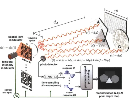
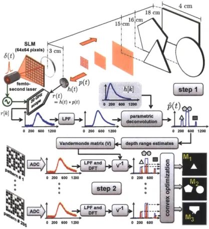
Natural scenes can often be approximated by planar facets. Here, we introduce a framework for acquiring the depth map of a piecewise-planar scene at high range and spatial resolution using only a single photodetector as the sensing element and a spatiotemporally-modulated light source as the illumination unit. In our framework (see Fig. 3-1), an omnidirectional, temporally-modulated periodic light source illuminates a spatial light modulator (SLM)
w
d A
b ff t - Q
spatial light fousng
modulator optics
s(t) =sin(t) (t- a
s(t -dc
N
temporal r(t) = sin(t - 2dA) + sin(t - 2d8) + sin(t - 2dc)
intensity photodetector scene
modulator 0 response #1 r[k] e IN ADC OUTrk]tlT. 16 time sampling (K samples/period) control 4
and sync scene reconstructed N-by-N
%f response #M pixel depth map
Figure 3-1: The proposed architecture for acquiring depth maps of scenes constituted of piecewise-planar facets. The scene is in far field, i.e., the baseline b and the dimensions of each planar facet w are much smaller than the distance between the imaging device and the scene. A light source with periodically-varying intensity s(t) illuminates an N x N-pixel
SLM. The scene is serially illuminated with M chosen spatial patterns. For each patterned
illumination the reflected light is focused at the photodetector and K digital time samples are recorded. The total M x K time samples are computationally processed to reconstruct an N x N-pixel depth map of the scene.
with an N x N pixel resolution, which then projects a chosen 2D spatial pattern on the piecewise-planar scene. The light reflected from the illuminated portions of the scene is then focused at a time-resolving photodetector and digitized into K digital samples by an analog-to-digital converter (ADC) that is synchronized with the light source. This measurement process is repeated M times; depending on the desired spatial resolution, M typically ranges from 1 to 5% of the total number of pixels in the SLM. The recorded time samples are computationally processed to obtain a 2D scene depth map at the same pixel resolution as
the SLM.
steps. Both steps exploit implicit or explicit modeling of the scene as piecewise planar.
Step 1 uses no spatial patterning from the SLM, i.e., a fully-transparent configuration.
Under the assumption that the scene is approximately piecewise planar, the continuous-time light intensity signal at the single photodetector is approximated well in a certain parametric class. Estimation of the parameters of the signal implies recovery of the range of depth values present in the scene. Note that the use of a parametric signal modeling and recovery framework [67,68] enables us to achieve high depth resolution relative to the speed of the time sampling at the photodetector. After discretizing the depths identified in this step, the remaining problem is to find correspondences between spatial locations and depths to form the depth map.
Step 2 uses many pseudorandom binary patterns on the SLM. The assumption that the scene is approximately piecewise planar translates to the Laplacian of the depth map being approximately sparse. We introduce a novel convex optimization problem that finds the depth map consistent with the measurements that approximately minimizes the number of nonzero entries in the Laplacian of the depth map. Solving this optimization problem with a general-purpose software package yields the desired depth map.
Outline
The remainder of this chapter is organized as follows: Section 3.1 establishes notation for our imaging setup. Sections 3.2 and 3.3 discuss the modeling and computational recovery associated with Steps 1 and 2, respectively, with the scene restricted to a single planar, rectangular facet for clarity of exposition. Section 3.4 describes the extensions of the frame-work that handle scenes with multiple planar facets that are not necessarily rectangular. The experiment is described in Section 3.5, and further extensions to textured scenes and non-impulsive illumination are discussed in Section 3.6.

![Figure 2-1: Sparsity of a signal (having a basis expansion or similar representation with a small number of coefficients significantly different from zero) is widely exploited for signal estimation and compression [44]](https://thumb-eu.123doks.com/thumbv2/123doknet/14398602.509581/26.918.198.692.152.341/sparsity-expansion-representation-coefficients-significantly-different-estimation-compression.webp)