Publisher’s version / Version de l'éditeur:
Canadian Geotechnical Journal, 8, 4, pp. 514-526, 1971-11
READ THESE TERMS AND CONDITIONS CAREFULLY BEFORE USING THIS WEBSITE.
https://nrc-publications.canada.ca/eng/copyright
Vous avez des questions? Nous pouvons vous aider. Pour communiquer directement avec un auteur, consultez la première page de la revue dans laquelle son article a été publié afin de trouver ses coordonnées. Si vous n’arrivez pas à les repérer, communiquez avec nous à PublicationsArchive-ArchivesPublications@nrc-cnrc.gc.ca.
Questions? Contact the NRC Publications Archive team at
PublicationsArchive-ArchivesPublications@nrc-cnrc.gc.ca. If you wish to email the authors directly, please see the first page of the publication for their contact information.
NRC Publications Archive
Archives des publications du CNRC
This publication could be one of several versions: author’s original, accepted manuscript or the publisher’s version. / La version de cette publication peut être l’une des suivantes : la version prépublication de l’auteur, la version acceptée du manuscrit ou la version de l’éditeur.
Access and use of this website and the material on it are subject to the Terms and Conditions set forth at
Transfer of heaving forces by adfreezing to columns and foundation
walls in frost-susceptible soils
Penner, E.; Gold, L. W.
https://publications-cnrc.canada.ca/fra/droits
L’accès à ce site Web et l’utilisation de son contenu sont assujettis aux conditions présentées dans le site LISEZ CES CONDITIONS ATTENTIVEMENT AVANT D’UTILISER CE SITE WEB.
NRC Publications Record / Notice d'Archives des publications de CNRC:
https://nrc-publications.canada.ca/eng/view/object/?id=1a5595df-db6a-4bef-92ed-15c074b4c2de https://publications-cnrc.canada.ca/fra/voir/objet/?id=1a5595df-db6a-4bef-92ed-15c074b4c2de
Transfer of Heaving Forces by Adfreezing to Columns and Foundation Walls
in Frost-Susceptible Soils'
E. PENNER AND L. W. GOLD
Geotechnical Section, Division of Building Research, Notional Research Colrncil of Canada, Ottawa, Canndn
Received May 28, 1971
T h e paper gives results of field studies o n uplift forces on small-diameter columns of steel, concrete, and wood caused by adfreezing in frost-susceptible Leda clay. Adfreeze strength values would appear to be highest for steel and concrete, followed closely by wood. T h e heav- ing pattern and the heaving force transmitted are shown t o be different for long foundation walls than for isolated columns. This compares favorably with the deformation pattern induced in an ice cover around offshore strl~ctures, during a change in water level. Attention is also given to the relative movement of the heaving soil with respect to the structure and the influence of the heave pattern o n the transmission of forces.
Cet article prksente les rksultats d'ktudes in situ des forces de soulivement, agissant sur des colonnes d e faible diamitre, en acier, en btton et en bois, et causkes par I'adhCrence de glace dans les argiles Leda gelives. Les valeurs d e resistance en adherence de la glace apparaissent les plus fortes pour I'acier et le beton, supirieures de peu celles observkes pour le bois. Le schkma d e soultvement de m i m e que la force d e soulevement transmise sont differents pour des murs de fondation longs et pour des colonnes isolkes. Dans ce dernier cas ils sont assez semblables aux schkmas de dkformation induits d a m un champ de glace slutour des structures 'off-shore' lors d'une variation du niveau d'eau. Le mouvement relatif du sol en soultvement par rapport a la structure de m&me que I'influence d u schema de soultvement sur la trans- mission des forces, sont egalement considkrks.
Adfreezing of soil to foundations and subse- quent uplift and distortion of relatively light structures is a serious problem in frost-suscep- tible soils if no special provisions have been made to avoid or counteract such forces. It is now well recognized that placing footings be- low the depth of frost penetration does not cir-
cumvent the problem of frost heave damage if
adfreezing of the soil to the foundation wall is permitted. Uplift forces caused by frost heaving in the active layer of permafrost areas have been shown to be substantial (Crory and Reed 1965; Vialov 1959). Adfreezing forces in areas of seasonal frost were studied and reported some years ago by Trow (1955) and more recently by Kinosita and Ono (1963), and Penner and Irwin (1969); they are also dis- cussed in recent translations of Russian studies (Tsytovich 1959; Saltykov 1944).
In areas of seasonal frost, the transmission of heaving forces by adfreezing is a common oc- currence in relatively light unheated buildings, transmission towers, transformer and distribu- tion station foundations, utility poles and posts.
'NRCC No. 12177.
Canadian Geotechnical Journal, 8 , 5 1 4 (1971)
Problems of frost heaving arise also at entrances to basement garages and various unheated structures attached to domestic dwellings such as garages and porches that are at least partially outside the thermal influence of the heated structure (Penner and Burn 1970).
A previous paper (Penner and Irwin 1969)
dealt with a study of heaving forces that re- sult from adfreezing on small-diameter steel pipes in frost-susceptible Leda clay during sev- eral winters. This field installation was subse- quently enlarged to permit comparisons of adfreeze strengths for small diameter columns of different materials, which is the subject of this paper. Also included in the study was a concrete block foundation wall for which the vertical forces due to heaving and the vertical movement of the ground surface in the vicinity of the wall were measured.
Adbeezing-Heaving Soil
Frost heave in soils is usually in the direction of heat flow and perpendicular to the plane of ice lenses. If the soil is frozen to a pile or foundation unit, heaving will impose a vertical force on it. "Adfreezing" or "frost grip" be- tween the soil and a structural element is not
PENNER AND GOLD: FROST HEAVlNG FORCES 515
harmful unless the lifting force transmitted is sufficient to heave the structure. Under field conditions the force developed on a structural unit will depend on the frost action characteris- tics of the soil and the size and geometry of the foundation. If displacement occurs it is seldom uniform and can cause destructive dis- tortion and cracking.
A knowledge of deformation behavior of fro-
zen soil around a foundation and of the nature of the bond between the soil and structure is required when calculating the forces that may be imposed. A number of possible types of de- formation for columns are shown in Fig. 1. The assumption in Fig. l a is that the frozen ground is a rigid body and that the frost heave displacement of this layer in relation to the fixed pile can occur only as a result of shear accompanied by crushing of ice crystals along the interface between the frozen ground and the pile. In Fig. l b the assumption is that the soil is firmly frozen to the pile and that the ultimate force transmitted depends on the elas- tic modulus and thickness of the frozen layer and the elastic modulus of the underlying ma- terial.
Saltykov ( 1944) carried out model studies
in the laboratory to establish the nature of the deformation of the heaving soil around fixed circular wooden posts. The deformation be- havior depicted in Fig. l c was shown to exist around 5-cm (2-in.) diameter wooden posts when heaving conditions were imposed. By placing horizontal layers of colored chalk be- tween layers of soil the deformation was shown to occur in the frozen soil within the 1-cm thick layer in contact with the column surface. He concluded that the assumed deformation characteristics used in earlier calculations by others, shown in Figs. l a and l b , were in- correct.
In field studies Saltykov also found that for an anchored pile 18 cm (7.1 in.) in diameter, the ground heaved the same amount ( 5 cm) from the pile as at some distance from the pile. Similar results with 33-in. (8.9-cm) steel pipes are reported by Penner and Irwin (1969). From the field studies it is difficult to determine whether the movement occurred at the interface between the pile and frozen ground or in a layer of soil adjacent to it.
Two other possibilities are given: Fig. I d shows elastic deformation in the soil in addi-
tion to some dislocation at the interface; Fig. l e shows elastic deformation in the soil away from
the column and some viscous deformation in
the soil close to the column.
Methods and Materials Site and Soil Conditions
The experiments on small footings were carried out on a 58 by 65 ft (17.7 by 19.8 m ) site located on National Research Council of Canada property in Ottawa which has been described in sorye detail in earlier papers (Penner and Irwin 1969; Penner 1970). The soil is a postglacial clay of marine origin com- monly referred to as Leda clay (Crawford 1961). The autumn moisture content is about 44%, and particle s u e analyses show that the soil consists of about 70% clay-size particles and 30% silt-size particles. The depth to bedrock varies between 11 and 20 ft (3.4 to 6.1 m ) . The bedrock served as a convenient means of anchoring the reaction frame for force measure- ments. The tcst site was cleared of snow throughout the winter to a distance of at least 10 ft (3.5 m) beyond the location of the test installations.
Design o f Reaction Frames for Columns and Foundation Wall
The reaction cross frame used for the circular columns is shown in Fig. 2. It consisted of two 6 I 123 steel beams anchored to bedrock at the four corners with $-in. (3.2-cm) expansion shell located at a depth of 2 ft (0.61 m ) below the bedrock surface. Each rock bolt assembly has a predicted breaking strength of 35 000 Ib (15 873 kg). The force measure- ments were made with a calibrated 10 000 Ib (4 535 kg) Dillon force gauge.
The reaction frame used to measure the heaving force on the 4-ft-long (1.22-m) concrete block wall has been described (Penner 1970). Basically it con- sisted of a reinforced H-frame of 6 I 123 steel beams anchored with four rock bolts to bedrock at a depth of 12 ft (3.66 m). The expansion shells were placed 18 in. (45.7 cm) below the rock surface. Force measurements were made with a calibrated 50 000 Ib (22 675 kg) Dillon force gauge located about 33 in. (8.9 cm) from the end of the frame (Fig. 3). A dummy gauge placed at an equal distance from the other end was designed to have approximately the same load deflection characteristics as the force measurement gauge.
Column Construction
The 33-in. o.d., 3-in. i.d. (8.9-cm o.d., 7.6-cm i.d.) steel columns consisted of rolled steel pipe. The pipes were filled with grease and capped to prevent internal convection due to thermal gradients. The outside sur- faces were washed with solvent to remove any grease before installation.
The wooden columns were turned to a 33 in. dia- meter (8.9 cm) from 4- by 4-in. cedar posts. At the time of installation the finished surface was smooth and clean. The concrete columns were made from premix concrete placed inside a 33-in. i.d. (8.9-cm) clear plastic pipe form. A reinforcing rod was placed down the center line of this column to improve the
CANADIAN GEOTECHNICAL JOURNAL. VOL. 8, 1971 mPILE T Y P E ( a ) D I S L O C A T I O N A T C O N T A C T I N T E R F A C E B E T W E E N F R O Z E N S O I L A N D P I L E . D U L T I M A T E U P W A R D F O R C E D E P E N D E N T O N SHEAR S T R E N G T H A T THE C O N T A C T FROST D E P T H P l L E A N C H O R A G E ) T Y P E ( b ) N O D I S L O C A T I O N B E T W E E N F R O Z E N S O I L A N D P I L E . U L T I M A T E U P W A R D F O R C E D E P E N D E N T O N M O D U L U S O F F R O Z E N L A Y E R TYPE ( c ) D E F O R M A T I O N W I T H I N L A Y E R O F F R O Z E N S O I L C L O S E T O P l L E S U R F A C E . F O R C E T R A N S M I T T E D T O P l L E D E P E N D E N T O N S H E A R S T R E N G T H O F F R O Z E N S O I L T Y P E ( d ) C O M B I N E D D I S L O C A T I O N O F ( a ) A N D D E F O R M A T I O N O F ( b ) TYPE ( e ) C O M B I N E D D I S L O C A T I O N O F ( 0 ) A N D D E F O R M A T I O N O F ( c ) N O T E : ( I ) o b c d G R O U N D S U R F A C E BEFORE H E A V I N G o ' b ' c ' d ' G R O U N D S U R F A C E A F T E R H E A V I N G ( 2 ) P l L E H E L D F I X E D I N A L L C A S E S W I T H RESPECT T O H E A V I N G S O I L
FIG. 1. Possible zone of dislocation and, regions of deformation in a frozen layer when a
F R A M E
PENNER AND GOLD: FROST HEAVING FORCES
I O N
CANADIAN GEOTECHNICAL JOURNAL. VOL. 8, 1 9 7 1 D U M M Y L I N E * Z S U R F A C E M A R K E R S t3/1FOR E L E V A T I O N S U R V E Y 6 I 1 2 ' 1 ~ STEEL B E A M G A U G F O R C E G A U G E C O N C R E T E B L O C K W A L L CENTER P O I N T O F R E A C T I O N F R A M E R O C K B O L T
LL-+-l
L I N E # 1 1 6 CENTER P O I N T O NY
R E A C T I O N F R A M E 6 I 12"2 STEEL B E A M R E A C T I O N F R A M E 5 0 . 0 0 0 L B D U M M Y G A U G E F O R C E GAUGE 6 I 12'12 STEEL B E A M 1112 " S P H A L T I C C O N C R E T E L A Y E R F R O Z E N S O l L RETE B L O C K W A L L U N F R O Z E N S O l LPENNER AND GOLD: FROST HEAVING FORCES
NOTE:
11
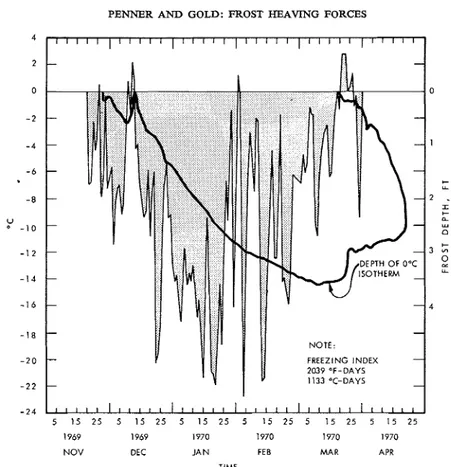
FREEZING INDEX1969 1969 1970 1970 1970 1970
NOV DEC JAN FEE MAR APR TIME
FIG. 4. Daily average temperature and frost depth 1969-70. strength and for ease of handling. By tapping and
vibrating the column it was possible to remove most of the air bubbles from the interface between the concrete and the plastic form, leaving a smooth finish on the outside surface.
Installation of Columns and Concrete Block Wall
Embedment of the 6-ft- (1.83-m) long columns was to a depth of 5 ft (1.52 m ) , leaving 1 ft (30.5 cm) of column above the ground surface. Columns were in- stalled by augering 6-in. diameter (15.2-cm) holes and backfilling to approximately the natural density with the same soil. The columns were fitted with a +-in. (1.27-cm) thick steel cap to distribute the load uniformly on the end of the column.
The concrete block wall was constructed in a trench 2 ft (0.61 m ) wide, 5 ft (1.52 m ) long, and 5 ft (1.52 m ) deep. The top of the block wall was about 8 in. (20.3 cm) above the ground surface. As with the columns, the space around the wall was backfilled and compacted to about the same density with the soil removed in excavation.
Soil Temperature Measurernents
Soil temperatures were measured at opposite corners on the site at least 10 ft (3.5 m ) inside the snow- cleared area to determine the 0" C isotherm for frost depths. Copper-constantan thermocouples were at- tached to I-in. (2.5-cm) diameter wooden dowels at 6-in. (15-cm) intervals to 43 ft (1.37 m ) . Readings
were recorded daily at 0830 h with a data-acquisition system. Air temperatures were obtained from a meteorological station located a few hundred yards from the test site.
Level Surveys
Level surveys, referenced to a rock-anchored bench- mark, were carried out weekly to measure the de- flection of the reaction frames directly above the force gauges. T o this was added the deflection of the Dillon gauges to obtain total movement of the column or foundation wall.
The deformation of the ground surface at right angles to the long dimensions of the block wall was also determined along two lines, as shown in Fig. 3. Lag bolts were installed in the asphalt surface at distances of 6 in. and 1, 2, 3, 4, 5, 6, and 7 ft (0.15 cm, and 0.30, 0.61, 0.92, 1.22, 1.53, 1.83, and 2.14 m ) from the wall for the ground level surveys.
Experimental Results
Thermal Conditions
The average daily air temperatures and the
frost penetration - time curve based on the
position of the 0" C isotherms at two locations on the site are given in Fig. 4. The maximum frost depth, 3.6 ft (1.09 m ) , was reached on 9
g."
1.
I
as 8 T O T A L F O R C E . L B T O T A L F O R C E . L B T O T A L F O R C E . L B2
-
rJ . w P .- .m.-
.? . w P . - .m.-
rJ w. P ."7 0 0 0 0 00 0 0 0 0 0 0 00 00 0 0 00 00 00 0 0 0 0 00 00 0 0 0 5. g 0 0 0 0 0 0 0 0 0 0 0 0 0 0 0 0 0 0 0 L" - I I I I I I I I I I I I I I I I,
-
"7 4 .- '7 4 .2 2 XDFREEZING STRENGTH, PSI ;;: 2 - -ADFREEZING STRENGTH. P S I g 2 .IADFREEZING STRENGTH, PSI
a ; :
8 Pd
_
I I I r- - m.. - 1 1 1 1 n I*--
I I I g .T 1 "7 - m - - N - v I o L " o 7 - -- " 7-o-V Nl oNv l - "7__
4- -
N 1 IX " 7OL "O . . . . . . - - 0 0 0 - . - N u -- 0 00 .. - N W 6 2 N - L" I I I I I I I I I I I I I 1 I I z- zPENNER AND GOLD: FROST HEAVING FORCES 521
TABLE 1. Adfreezing strength on columns At Peak Force 2
At Peak Force 1 Feb. 28-Mar. 1, Average for Average for Average for
Jan. 23-30, 1970 1970 Jan. 1970 Feb. 1970 Mar. 1970
p.s.i. kg/cm2 p.s.i. kg/cm2 p.s.i. kg/cm2 p.s.i. kg/cm2 p.s.i. kg/cm2
Steel 1 4 . 0 0 . 9 8 16.5 1 . 1 6 13.7 0 . 9 6 1 2 . 4 0 . 8 7 8 . 8 0 . 6 2
Concrete 1 9 . 5 1.37 1 3 . 0 0.91 1 7 . 0 1 . 2 0 1 0 . 3 0 . 7 2 5 . 7 0 . 4 0
Wood 1 3 . 0 0.91 9 . 0 0 . 6 3 1 2 . 0 0 . 8 4 7 . 0 0 . 4 9 4 . 8 0 . 3 4
March 1970. This frost depth curve was used to estimate the length of columns and founda- tion wall attached to the frozen soil for calcula- tion of unit adfreezing forces as the winter progressed.
Column Studies-Concrete, Steel, and Wood
The force measurements, calculated adfreez- ing strengths and vertical column movement under these forces, given in Fig. 5, are based on the average of two installations of each column type located randomly on the test area. Ad- freezing strengths were calculated by dividing the total measured force by the area of the column within the frozen layer.
Maximum movement of the steel columns was 0.028 ft (0.853 cm), 0.014 ft (0.427 cm) for concrete and 0.01 1 ft (0.335 cm) for wood. These movements were due to the deflection of the force measurement gauge, reaction frames and rock bolt assembly.
There are some noticeable differences in unit area adfreezing strengths in the early part of the winter season. Although the total forces were low, the calculated adfreezing strengths were high for both the wood and concrete col- umns. These differences may be attributable to the different thermal regimes in the soil induced by the various column types. Measurements in more recent studies at the Division of Building Research have shown that the temperatures of wood and concrete columns and the depth of
the 0" C isotherm closely follow the ground temperature pattern in the surrounding area. This point has not been resolved for steel columns with similar depths of embedment in the ground and length of column above the ground surface, nor is such information avail- able in the literature. The possibility exists therefore that during the early winter, the steel columns may be warmer than those composed of wood or concrete because of greater heat conduction from the warmer strata below.
Two peaks of load are evident for all col- umns. The first one occurred between 23 and 30 January and the second at the end of Feb- ruary and early March. A comparison of ad- freeze strengths for the columns may be made on the basis of peak values. A further compari- son between columns can be obtained from the average monthly adfreezing force during January, February, and March. These results are given in Table 1.
During the months of January and February the adfreeze strengths remained consistently high for the steel columns which were ap- parently not so subject to change resulting
from short warm or cold periods-a few days
in duration-as were the wood and concrete
columns. It may be concluded from these field results that the adfreeze strength on wood is somewhat less than for steel or concrete. The overlap in results for these two materials does not allow a conclusion as to which has the higher adfreezing strength. The values obtained for steel columns compare well with results from other winters (Penner and Irwin 1969).
Concrete Block Foundation Wall
The results for the foundation wall concern- ing total heave force, calculated adfreeze strength and vertical movement are given in Fig. 6. The vertical movement of the wall asso- ciated with the deflection of the reaction frame
and the Dillon gauge was 0.01 8 ft (0.548 cm)
.
This maximum was reached, as would be ex- pected, when the vertical load was at a maxi- mum.
The maximum load of 3 1 000 lb ( 14 062
kg) occurred at the end of February, which corresponds to the time of the second peak for the columns. With the exception of a few peaks occurring early in the winter, the adfreez- ing strengths based on the measured depth of frost penetration on the site and the surface area of the wall within the frozen layer ranged
CANADIAN GEOTECHNICAL JOURNAL. VOL. 8, 1971
5 15 25 5 15 25 5 15 25 5 15 25 5 15 25 5 15 25 5 15 25 1969 1969 1970 1970 1970 1970 1970 NOV DEC JAN FE B MAR APR MAY
TIME
FIG. 6. Measured force, calculated unit adfreezing strength and vertical strain of concrete block wall during heaving period.
from 6.5 to 9 p.s.i. (0.46 to 0.56 kg/cm2). At the time of the maximum load (end of Febru- ary) the adfreeze strength was 6.5 p.s.i., which is less than half the adfreeze strengths on the small-diameter concrete columns for the same period.
Comparison of Heaving Force on Columns and Straight Foundation Walls
The heaving pattern around small diameter steel columns observed at the present site in 1966-67 and 1967-68 has been described (Penner and Irwin 1969). During these periods the maximum heaving load on 3+-in. diameter steel columns was in excess of 6 000 Ib, giving a maximum average shear stress of approxi- mately 12.5 p.s.i. (0.9 kg/cm". The heaving pattern, shown in Fig. 7, shows a uniform heave within a 3-ft (0.92 m ) radius of the column. Measurements were not made within a
1-ft radius of the column.
The pattern of heave at right angles to the long axis of the foundation wall was quite different. The average of the heave measure- ments on lines Nos. 1 and 2 (Fig. 3 ) are given
in Fig. 8. The figure shows a very pronounced
differential heave which started early in the winter and increased in severity as the winter progressed. The maximum heave of 0.26 ft (7.93 cm) at a distance of 7 ft (2.14 m ) from
the wall is equal to the maximum measured elsewhere on the site at a location not influenced by structures, indicating that the influence of the wall does not extend much beyond 7 ft
(2.14 m ) . A comparison of the heaving force throughout the winter gives higher values for the concrete columns than for the concrete walls. At the time of maximum load (end of February) the ratio was about 2: 1.
A qualitative appreciation of the reason for the shear stress developed on piles being ap- preciably greater than that developed on a long straight wall by the same amount of frost heave can be obtained from a consideration of the analogous problem for ice covers. The assump tion that an ice cover behaves as an elastic plate on an elastic foundation gives an upper bound to the vertical shear stress that the cover will exert on a structure due to a change, H,
in water level.
Consider first an isolated pile of radius a, frozen into a cover of thickness h. By St. Venant's principle, the shape of the deflected surface of the cover to within a relatively close distance of the pile will be the same as that caused by an equivalent uniform vertical load applied to the surface of the cover over an area of radius a.
Let Q,, be the total shear load applied by the ice cover to the surface of the pile, q, the shear
PENNER AND GOLD: FROST HEAVING FORCES
0 . 4 0
3 2 1 1 2 3
D I S T A N C E F R O M C E N T E R L I N E O F F O O T I N G , FT
FIG. 7. Surface heave around anchored column for 196667.
-
stress, and p the equivalent uniform surface
load. Then,
Q, = 2nahqp = na2p
and
I
According to Wyman (1950), the maximum deflection under the load due to the application of a uniform pressure p to the surface of an ice cover over an area of radius a is
c21 W =
St
P
(1+
b ker' b)-
-
-
-
wherek = the modulus of subgrade reaction
ker'b = the first derivative of one of the modified Bessel functions,
-
-
-
(i o f F o o t i n g
-
and 1, = radius of relative stiffness c41 E = Young's modulus
-
-
-
-
-
1
FEB 14/67-
-
-/ FEB 14/67 JAN 17/67-
MAR 15/672-'---,---- -
-=---,---
JAN 4/67>-
JAN 4 / 6 7-
-
-
-
-
-
-
-
-
MAR 26/672----
-
=
=---
-
,--
-
- 1 M A R 26/67-
--
-
--
--
- C D E C 19/66-
-
--
--
-
-
-
7 DEC 6/66 7-
---
-
--
- APR 12/67 --
-
-
-
-
-
-
--
NOV 21/66 - I ~ N O 21/66 V-
-
I -h v = Poisson's ratio.For b
<
0.15, which is not an unreasonable assumption for the problem under discussion,nb2
I
+
b ker' b-
-8
(Wyman (1950) p. 301). Substituting Eqs. [1], 131, and [4] into [2] gives
nha w = 7 q p 4k1,
Consider now the vertical force exerted by the cover when it is frozen to a long straight wall. Let this shear force per unit width be
524 CANADIAN GEOTECHNICAL JOURNAL. VOL. 8. 1971 I I I I I I I I
-
0 MAR 16, 1970 - --
-
o J A N 12,1970 0 J A N 5, 1970 - 0 DEC 30, 1969-
-o--o-O DEC 23, 1969-
-
O 0 DEC 9 , 1969-
-
--
- - VERTICAL DISPIACEMENT OF FOUNDATION AT M A X I M U M-
I I I I I I I I 0 0 1 2 3 4 5 6 7 8 9 D I S T A N C E F R O M W A L L , FTFIG. 8. Ground surface heave at right angles to the long axis of the concrete block founda- tion wall (average of line #1 and #2, Fig. 3 ) .
where qw is the shear stress. Gold (1968) gives for From the foregoing it can be appreciated that
the dependence of the shear force on the change the ratio of the shear stress on the pile to that
in water level : on the wall due to the same amount of frost
C8l 4,
=
Hlwk7
heave depends on the geometry of the deflectionof the ground. For the case of the pile the de-
where flection of the ground would be bowl shaped.
c91 3k(l
-
v2) The total upward force developed due to re- straining the ground in this way is resisted only by the shear force at the surface of the pile. In Solving for H in Eq- I81 and equating to W , Eq.the case of the long straight wall, each unit [6] gives
4 length of wall must restrain only the deflected
1101
a=-
qw n a d lp strip of the same width perpendicular to it. Theassumption of elastic behayior gives the maxi-
For a = 1.75 in. (4.44 cm) mum difference in stress that could occur for
Clll
3
=
0.5lp
the same amount of heave. This differenceqW could be approached, for example, if an ice
F~~ the elastic deflection of an ice cover 24 cover were subjected to a rapid change in water
in. thick (61.0 cm), 1, = 430 in. (10.9 rn). level.
q u a t i o n ~ 1 1 1 indicates that for this condition Both ice and frozen soils are viscoelastic
the shear stress developed on a 3f-in. diameter materials. For engineering calculations it is
pile would be about 200 times greater than often assumed that the stress dependence of
that developed on a long straight wall for the the strain rate has the form
PENNER AND GOLD: F 'ROST HEAVING FORCES 525
where
7
is the shear strain rate due to the shearstress z, and d and n are constants for given temperature. The value of n has been found to be between 2 and 3.
For a given change in water level or amount of heave, time-dependent deformation will de- crease the effective values of the characteristic lengths I , and I , and thereby reduce the shear stress developed on the pile or wall. In addi- tion, shear flow will occur relatively much more rapidly around the pile than near the wall be- cause of the higher shear stress induced for a given heave and the power law dependence of the shear rate on the shear stress. These effects will reduce the ratio of the shear stress on the pile to that on the wall.
The observations show that for the conditions of the study, this ratio was reduced to about 2. Equation [12] indicates that for this ratio in shear stress, the strain rate at the pile would be
4 to 8 times that at the wall. Measurements of the deflection showed that the rate of strain induced in the soil for the pile was sufficiently large that the deformation associated with heave was confined to a relatively thin zone immedi- ately adjacent to it. For the wall, the stresses were sufficiently small that the zone of shear deformation (i.e. the region of deflected sur- face) extended a significant distance from it. A viscoelastic theory relating adfreezing forces developed on structures of various geometries to heave and the rate of heave is still to be developed.
Mention should also be made of the effect of temperature. The shearing resistance of frozen ground and ice increases with decrease in temperature. In the present study it was assumed that this resistance was constant over the full surface of adfreezing for both the pile and the wall. As the temperature of the ground increased with depth to about 0" C at the freezing plane, the resistance to shear would have decreased correspondingly. This effect should be kept in mind when interpreting the results.
General Discussion and Conclusion
The experimental results show that the pat- tern of heave and the adfreezing forces are influenced by the shape and size of the struc- ture to which the heaving soil is frozen. This is in agreement with the theoretical considera-
tions based on the ailalogy between the lifting force of ice sheets on structures of different geometry and that of a frost-heaving layer.
The heave pattern around columns and movement of the frost heaving soil adjacent to
a circular column appears to be either type (a)
or (c) as shown in Fig. 1. From these studies it is not possible to differentiate between these two types. Adjacent to long foundation walls the heave pattern is either type (d) or ( e ) and there is a noticeable and well defined depen- dence of heave on distance from the founda- tion. It is not easy to determine in the field whether the frozen soil slides along a column or foundation wall or shears in the soil immedi- ately adjacent to structures. Such studies should probably be carried out in the laboratory. Finally, it would appear that under field condi- tions the heaving forces transmitted to wood columns are somewhat less than those trans- mitted to concrete and steel columns.
Acknowledgment
The authors wish to thank their colleagues in the Geotechnical Section for assistance,
comments, and criticism, and particularly D.
Eldred for many of the measurements and R. Frederking for helpful discussions of strength and deformation behavior of ice sheets around structures. This paper is a contribution from the Division of Building Research, National Research Council of Canada and is published with the approval of the Director of the Divi- sion.
CRORY, F. E., and REED, R. E. 1965. Measurement of frost heaving forces on piles. U.S. Army Mater. Command, Cold Reg. Res. Eng. Lab., Hanover, N.H. TR 145.
CRAWFORD, C. B. 1961. Engineering studies of Leda clay soils in Canada. Roy. Soc. Can. Spec. Rep. No. 3, University of Toronto Press (Revised
1965).
GOLD, L. W. 1968. Vertical forces due to ice. In Ice pressures against structures. Nat. Res. Counc. Can., Assoc. Comm. Geotech. Res., Tech. Memo. 92, Ottawa. pp. 150-151.
KINOSHITA, S., and ONO, T. 1963. Heaving forces of frozen ground. I. Mainly on the results of field research. Low Temp. Sci. Lab., Teron Kagaku, Ser. A, 21, pp 117-139. (Nat. Res. Counc. Can., Ottawa, Tech. Translation 1246, 1966).
PENNER, E. 1970. Frost heaving forces in Leda clay. Can. Geotech. J., 7(1), pp. 8-16.
526 CANADIAN GEOTECHNICAL JOURNAL. VOL. 8, 1971 frost heaving of foundations. Nat. Res. Counc.
Can., Div. Build. Res., Can. Build. Dig. 128. PENNER, E., and IRWIN, W. W. 1969. Adfreezing of
Leda clay to anchored footing columns. Can. Geotech. J., 6(3), pp. 327-337.
SALTYKOV, N. I. 1944. Calculating frost heaving forces on foundations. Izvestiia Akademii Nauk SSSR, Otdelenie Tekhnickeskikh Nauk, No. 6, pp. 305-412. (Translation 46 by Jaroslov J. Peel, SIPRE Bibliography Project, Library of Congress, Washington.)
TROW, W. A. 1955. Frost action on small footings. Highw. Res. Board, Washington, Bull. 100, pp. 22-27.
TSYTOVICH, N. A. 1959. Principles of geocryology; Part 11, Engineering geocryology; Chapt. 111, Basic mechanics of freezing, frozen and thawing soils, pp. 28-79. (Nat. Res. Counc. Can., Ottawa, Tech. Transl. 1239, 1966.)
VIALOV, S. S. 1959. Reologicheskie Sovistva i Nesush- chaia Sposobnost Merzlykh Gruntov. Izdatel'stov Akademii Nauk SSSR, Moscow. (Rheological properties and bearing capacity of frozen soils.) U.S. Army Mater. Command, Cold Reg. Res. Eng. Lab., Hanover, Tech. Translation 74, Sep- tember 1965.
WYMAN, M. 1950. Deflections of an infinite plate. Can. J. Res. Ser. A, 28, pp. 293-302.