HAL Id: hal-01539445
https://hal.archives-ouvertes.fr/hal-01539445
Submitted on 14 Jun 2017
HAL is a multi-disciplinary open access
archive for the deposit and dissemination of
sci-entific research documents, whether they are
pub-lished or not. The documents may come from
L’archive ouverte pluridisciplinaire HAL, est
destinée au dépôt et à la diffusion de documents
scientifiques de niveau recherche, publiés ou non,
émanant des établissements d’enseignement et de
Regular and lightweight mobility management in the
HIP-based M2M overlay network
Amine Dhraief, Abdelfettah Belghith, Khalil Drira
To cite this version:
Amine Dhraief, Abdelfettah Belghith, Khalil Drira. Regular and lightweight mobility management in
the HIP-based M2M overlay network. International journal of autonomous and adaptive
communi-cations systems, Inderscience Publishers, 2016, 9 (3-4), pp.331-352. �10.1504/IJAACS.2016.079628�.
�hal-01539445�
Regular and Lightweight Mobility Management
in the HIP-Based M2M Overlay Network
Amine Dhraief and Abdelfettah Belghith
HANA Research Group
University of Manouba, 2010 Manouba, Tunisia
[email protected]
Khalil Drira
CNRS, LAAS, 7 avenue du colonel Roche, F-31400 Toulouse, France
Univ de Toulouse, LAAS, F-31400 Toulouse, France
[email protected]
Abstract
The host identity protocol (HIP) based machine-to-machine (M2M) overlay network is a virtual, self-organized and secure M2M network build on the top of the Internet. M2M devices forming this overlay network may change their point of attachment to the overlay while having running sessions. HIP provides a na-tive mobility support to these M2M devices. However, this support is not adapted for the M2M context. We propose in this paper a regular and lightweight mobil-ity strategies to efficiently handle M2M devices mobilmobil-ity within this overlay. We first analytically assess the signalling cost of the regular and lightweight mobil-ity strategies. Then, we evaluate the application recovery time of an M2M device experiencing a mobility episode through simulation. Both signalling cost analy-sis and simulation results show that our lightweight mobility strategy significantly out-performs regular HIP.
Keywords: HIP; M2M; Mobility support; Overlay networks; Signalling cost; Ap-plication recovery time; OMNeT++
Biographical notes:
Dr. Amine DHRAIEF received his Ph.D. degree in computer science from Tele-com Bretagne University of Rennes I in 2009, his Master of Science degree and his Engineering degree both in computer science from the National School of Computer Sciences (ENSI), the University of Manouba respectively in 2006 and 2005. He is cur-rently an Assistant Professor of Computer Science at ISIGK, University of Kairouan, Tunisia. He is also a senior member of the HANA research group at the National School of Computer Sciences. His current research interests include pervasive and
ubiquitous computing and Machine-to-Machine communication. He is currently a member of IEEE, ComSoc and VTS.
Dr. Abdelfettah BELGHITH received his Master of Science and his PhD degrees in computer science from the University of California at Los Angeles (UCLA) respec-tively in 1982 and 1987. He is since 1992 a full Professor at the National School of Computer Sciences (ENSI), University of Manouba, Tunisia. His research interests include computer networks, wireless networks, multimedia Internet, mobile comput-ing, distributed algorithms, simulation and performance evaluation. He runs several research projects in cooperation with other universities, research laboratories and re-search institutions. He is currently the Director of ENSI and the Director of the Doc-toral School (Graduate School) STICODE of the University of Manouba. He is a senior member of IEEE, a member of the IEEE ComSoc, and the Chair of the IEEE Tunisia Section.
Pr. Khalil DRIRA received the Engineering and M.S. (DEA) degrees in Computer Science from ENSEEIHT (INP Toulouse), in June and September 1988 respectively. He obtained the Ph.D. and HDR degrees in Computer Science from UPS , University Paul Sabatier Toulouse, in October 1992, and January 2005 respectively. He was from oct 1992 to spet 2010, Charg´e de Recherche, and he is since oct 2010 research direc-tor, a full-time research position at the French National Center for Scientific Research (CNRS). Khalil DRIRA’s research interests include formal design, implementation, testing and provisioning of distributed communicating systems and cooperative net-worked services. Khalil DRIRA is or has been member of the programme committees of international and national conferences. He is member of the editorial board of dif-ferent international journals in the field of software architecture and communicating and distributed systems. Khalil DRIRA has been editor of a number of proceedings, books and journal issues in these fields.
1
Introduction
Machine-to-Machine (M2M) communication is a novel communication technology which is witnessing an unprecedented growth Juniper Networks (2011); Uusitalo (2006). The European Telecommunications Standards Institute (ETSI) is currently standardis-ing this novel technology. ETSI defines an M2M network as a set of M2M devices capable to detect at real-time events and transmit them via M2M gateways towards a distant M2M applications ETSI Technical Committee Machine-to-Machine commu-nications (M2M) (2011). This novel concept is considered as the new hype of the Internet and the future of our communication society Wu et al. (2011) as it covers a wide range of application from smart homes Zhang et al. (2011), smart-grids Fadlullah et al. (2011), vehicular technology Wu et al. (2011) and e-health Lu et al. (2011).
The M2M area network includes heterogeneous devices such as smart objects, me-ters, actuators and sensors, having different access technologies and scattered through the Internet. Thus, building an M2M overlay network would certainly alleviate this heterogeneity. Furthermore, ensuring a private M2M network in order to secure data
exchanged within an M2M network is a fundamental challenge. For this purpose, we built a HIP-based M2M overlay network (HBMON), a virtual and private M2M net-work Dhraief et al. (2012, 2013a). Our solution relies on the host identity protocol (HIP) functionalities to define and self-organise our M2M overlay Moskowitz et al. (2008). According to the targeted application, M2M devices can either be static or mobile nodes. Mobile nodes usually perform a layer 2 (L2) handover which may be followed by a layer 3 (L3) handover. The L2 handover is change in the layer 2 (link-layer) connectivity (i.e., the change from one access point to another one); whereas, the L3 handover refers to a change of the access network (i.e., the change from one access router to another one) and the acquisition of a new IP address. As a result of the L3 handover, current end-host IP address is changed to a new topologically correct one. IP addresses have a dual role, they are considered at the same time end-host loca-tors and session identifiers. Without an adequate support, running transport session are broken as a consequence of the L3 handover. To ensure transport session survivabil-ity upon movement, session identification should remain stable while end-host locator is changed. HIP addresses this issue by introducing a new stable cryptographic Host Identity Tag (HIT) as node identifier Moskowitz et al. (2008). Hence, HIP is supposed to natively provide mobility support to the M2M devices within our overlay without adding any modification.
In this paper, we first study to what extent regular HIP can manage end-host mo-bility within our M2M overlay network. Then we propose a set of enhancement to regular HIP in order to provide a lightweight mobility support to the M2M devices. Both signalling cost analysis and performance evaluation through simulation show that our lightweight mobility support strategy significantly out-performs regular HIP. The remainder of this paper is structured as follows. Section II is a related work section. It first presents the Host Identity Protocol and its native mobility supports. Then it details the HIP-based M2M overlay network architecture. Section III presents our con-tribution, the regular and the lightweight end-host mobility management within our M2M overlay network. Section IV compares the two signalling costs of these two M2M device mobility strategies. Section V presents a performance evaluation of both strategies. Section VI concludes this paper.
2
Related works
Mobile IPv6 (MIPv6) protocol families are the de facto standard in managing end-host mobility at the IP layer. Minoli (2013) suggests to use MIPv6 technologies to handle M2M device mobility. Nonetheless, MIPv6 does not have a native security support and if security is not provided for M2M communications, the M2M paradigm will not be widely adopted. For this purpose, we use the Host Identity Protocol (HIP) Nikander et al. (2008); Moskowitz and Nikander (2006), a host-centric mobility and multihoming protocol to efficiently handle M2M device mobility. One of the major advantage of HIP is its native security support as it relies on cryptographic namespace. In the following, we first give an overview of the host identity protocol (HIP) protocol and focus on the native HIP mobility support. Then we present the HIP-based M2M overlay network (HBMON) architecture.
2.1
The host identity protocol
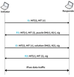
One of the major limitation of the current TCP/IP stack is the dual role of the IP address, it is at the same time an endpoint locator and a connection identifier. HIP alleviates this problem by introducing a new cryptographic namespace (Host Identity Tag (HIT)) in order to uniquely identify each node in the Internet, and consequently it decouples node identity from its localisation Nikander et al. (2008). While the IP address might change, the node cryptographic identity remains stable Henderson et al. (2003). HIP introduces a new sub-layer in the TCP/IP stack located between the IP and the transport layer which rewrite the IP address into a HIT and vice versa. HIP also maintains a context per HIT pair which holds information about the established session between these two end-hosts. The HIP context is established after a four-way handshake control messages I1,R1,I2,R2 (see Figure 1). This mechanism, called base exchange, is based on a secure exchange of cryptographic keys to authenticate communicating hosts: the initiator and the responder. The former is a host wanting to share a communication context with another host, sends a trigger packet called I1 to the destination. The latter is the host receiving I1, sends a response called R1 packet containing a puzzle to authenticate the initiator. Upon receiving R1, the initiator solves the puzzle, sends I2 containing the solution and waits for the responder confirmation to establish a HIP associationMoskowitz et al. (2008).
Figure 1: HIP base exchange
The HIP communication between two hosts is based on a security association (SA) which is established upon the HIP base exchange Moskowitz et al. (2008). A SA is a set of security parameters agreed by two hosts in order to encrypt and authenticate trans-ferred data. However, several SAs may be established between two hosts such as each
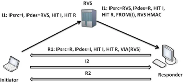
SA has its own identifier which is called Security Parameter Index (SPI). The main role of the HIP layer is to demultiplex incoming packets to host identity tag (HIT) using the SPI value in the packet and to multiplex outgoing packets to the address source and interface according to the SPI value in the received packet. HIP also introduces in the network architecture a proxy element called a Rendez-vous Server (RVS) Laganier and Eggert (2008). Each HIP node registers itself at the RVS. The RVS maintains a binding between the set of the available IP address in the HIP node and its HIT. Whenever a change occurs in the IP address, the HIP node updates its RVS registration with the new information. HIP node may also interact with the RVS element while establishing the HIP context. Figure 2 illustrates a scenario of a HIP association using the RVS. When a HIP node wants to establish a HIP association with a node known only by its HIT, it sends the I1 packet to the RVS indicating the Responder HIT. The RVS resolves the destinator HIT into an IP address and relays the packet to the destination. After receiv-ing an incomreceiv-ing I1 packet from a RVS, the Responder directly answers the Initiator with an R1 message. The VIA(RVS) parameter included in the R1 message indicates the IP address of the used RVS in the I1 message. The HIP context establishment is then performed Laganier and Eggert (2008).
Figure 2: HIP base exchange through rendez-vous server
2.1.1 HIP mobility support
In a HIP network, the locator is not only an IP address but also a key indexing the correspondent security association Nikander et al. (2008). Thus, when one of the two HIP nodes having an ongoing communication changes its current attachment point to another one, it acquires a new IP address and changes the SPI into SA. So, the mov-ing HIP node has to report to the correspondent node about its new locator in order to maintain the HIP SA. In the following, we illustrate how HIP support mobility. The basic HIP mobility scenario is illustrated as follows. For setting up the HIP mobility
mechanism, there are two ways to be considered; either, mobility with a single SA pair (only one IP address bound to an interface) without re-keying or mobility with a single SA pair with re-keying Nikander et al. (2008). In the former case, which is the simplest one, when the mobile host moves and obtains a new IP address, it notifies the correspondent host sending an UPDATE message containing the new IP address in the LOCATOR parameter and the Old SPI and New SPI values in ESP-INFO parameter. When the correspondent host receives the UPDATE packet, it checks the new address and makes it UNVERIFIED in the interim, while the old address is DEPRECATED. Then it acknowledges the mobile host by the second UPDATE message which contains an ECHO REQUEST to validate the new peer address. As well, it includes ESP INFO with Old and New SPIs set to the current outgoing SPI. Lastly, once receiving the sec-ond UPDATE message, the mobile node sends the last UPDATE message including an ECHO RESPONSE in order to definitely validate the new address. Indeed, when the correspondent host receives this ECHO RESPONSE, it automatically marks the new address as ACTIVE and removes the old address. For the second case, a new ESP ses-sion key will be regenerated. The mobile host sends the UPDATE message containing a new SPI for the incoming SA. The correspondent host upon receiving the UPDATE message, executes the re-key and replies with the a second message containing its own new SPI.
2.2
HBMON architecture
The HBMON Dhraief et al. (2012) aims to use HIP functionalities in order to build an M2M overlay network on the top of an existing IP network. In the following we detail the architecture of our solution. The HBMON consists of an M2M device equipped with HIP functionalities connected to a HIP Rendez-vous server (RVS) and a set of Correspondent Nodes (CNs) containing several M2M applications. Before establishing a communication context, the M2M device triggers a process to build an overlay on top of an existing IP network. The RVS acts as an M2M gateway (as specified by the ETSI ETSI Technical Committee Machine-to-Machine communications (M2M) (2011)) between the device or the application and the Internet. When a device wants to communicate with a CN, it firstly, registers with the closest RVS in its area and stores a binding between the set of the available IP addresses and its HIT. Secondly, it collects required information about nodes participating to the overlay. This phase is called “HBMON definition” and ends with the distribution of all collected information about the overlay to the CN’s RVS. Finally, each node within the overlay acquires a private IPv6 address used as device/application locator in the overlay. This process is delegated to the device RVS. In the following, we detail the steps required to build our HBMON.
2.2.1 HBMON definition
We modify the HIP basic exchange mechanism in order to define and distribute the information about our M2M overlay. We append the HIP basic exchanged messages I1,R1, I2 and R2 with new fields related to the overlay definition and add new HIP sig-nalling message to distribute the overlay information among the members. The
initia-tor of the HBMON triggers the mechanism “HBMON definition” by sending I1 packet containing new field named REQUEST-HBMON. Once the responder receives I1, it acknowledges the initiator by the R1 packet containing an ACK-HBMON. When the initiator receives the R1 packet, it sends an RVS-Discovery packet to a pre-defined any-cast address to discover the nearest RVS. The responder performs the same discovery process. The RVS-Discovery packet based on anycast address is a new HIP signalling message. After the discovery of the RVS, the initiator sends the I2 packet containing the encrypted IP address and the HIT of the RVS as well as the HBMON-ID. Upon re-ceiving the I2 packet, the responder stores the initiator’s RVS IP address, the HIT and the HBMON-ID. Then, it replies by R2 packet. The R2 packet contains the encrypted address and the HIT of the RVS discovered earlier by the responder. After receiving the R2 packet, the initiator stores all the information related to the HBMON defini-tion into a HBMON context and sends them into a CONTEXT packet to the RVS’s IP address. The HBMON context includes the following records (HBMON Tag, I HIT, R HIT, I IP, R IP, RVS IP). HBMON Tag is an identification of the current context established between the two hosts. This context tag is generated by the initiator and is included in all HBMON packets. I HIT and R HIT are the Host Identity Tag of the initiator and the responder. I IP and R IP are the IP addresses of the initiator and the responder. Finally, RVS IP is the IP address of the currently used RVS. The CONTEXT packet is a new HIP signalling message. The correspondent RVS receives the CONTEXT packet and stores all information about HBMON definition. Then, it sends in multicast this information to all RVSs already registered in the context. Each correspondent RVS receives this information and stores them.
2.2.2 HBMON address configuration
After collecting and distributing information about the overlay members, HBMON initiator’s RVS creates an IPv6 network prefix and distributes it to all the overlay mem-bers. Firstly, the initiator’s RVS periodically broadcasts the new IPv6 into its own AS in an ICMP message similar to the IPv6 Router Advertisement (RA) with the same fields and flags augmented with the Overlay ID in a separate field. Nodes receiving this message, extract the prefix and the Overlay ID and configure a private IPv6 ad-dress. Secondly, all the RVSs pre-register themselves into a specific multicast group in order to receive the network prefix from the initiator’s RVS. The initiator’s RVS sends the address configuration message to the RVSs’s multicast group. Each RVS receiving a multicast message that contains the network prefix, diffuses it into its own address AS. Finally and after configuring their private addresses, the overlay members send an update message to their RVS to store a binding between their private addresses and their HITs.
3
M2M device mobility management within the
HB-MON
As mentioned in section 1, the HBMON consists of M2M mobile devices that fre-quently change their points of attachments. While moving, an M2M mobile device
acquires a new topologically correct IP address. As a consequence of this movement, previously established transport sessions with the old IPv6 address are interrupted. Hence, we need to define an adequate support to manage M2M device mobility within our overlay network. In this section, we first present the fundamental requirements that our M2M devices mobility management solution should satisfy. Then, we detail our contribution.
3.1
Mobility requirements
Solving mobility problem in HBMON involves a lot of requirements that need to be fulfilled. We detail in the following these requirements.
• Location management: When a HBMON mobile node (HMN) executes a Layer 3 handover and acquires a new IP address, its correspondent peers should be in-formed about its new location.
• HBMON context update: All the RVSs members of the HBMON should be informed about any location update of the HMN. Otherwise, information stored within the HBMON context will be obsolete.
• Transparency to upper-layers: Obtaining a new topologically correct IP ad-dress leads to the disconnection of the established sessions Dhraief and Mon-tavont (2009). An M2M device mobility management solution should preserve running sessions.
• Security: HBMON members frequently change their locators (IP addresses) while having stable session identifiers. In the HBMON context, a binding exists between the current HMN locator and its identity. A malicious node can intro-duce a false binding between the HMN locator and its identity either to hijack the session or to flood a HMN victim with unwanted traffic. Therefore, our so-lution should provide the appropriate mechanisms to prevent both hijacking and flooding attacks
• Simultaneous movements (Double jump): The Simultaneous mobility or the double jump case occurs when two mobile nodes change their locations at the same time while having an ongoing communication. As the probability of simul-taneous mobility event is non-trivial in a mobile environment Wong and Woon (2007), our solution fully supports the double jump case within the HBMON as we proposed in Dhraief et al. (2013b).
• Performance: Our solution should scale with the number of HBMON members and should not introduce any signalling storm.
3.2
End-host mobility management in the HBMON
To address the mobility requirements presented earlier, we propose in the following a novel solution based on the enhanced use of the HIP RVS functionalities to ensure
session survivability between HBMON members. In our solution, we use the IPv6 pro-tocol suite to handle layer 3 addressing and routing functionalities. This assumption is motivated by the fact that the number of M2M devices may reach 7 trillions devices in the forthcoming years Uusitalo (2006). First of all, an M2M device, member of the HBMON, performs a layer 2 (L2) handover. Once the layer 2 connectivity is es-tablished, the M2M device receives an IPv6 router advertisement from the new access router and configures a new global IPv6 address. At this stage, both M2M devices corresponding peers and the HBMON RVSs are not aware about the M2M device new location. To correctly handle the HBMON mobile nodes (HMN) mobility, we intro-duce in the HIP protocol the following signalling messages: (i) RVS Discovery: This signalling message allows to discover the nearest HBMON RVS (NHRVS). This mes-sage is sent in anycast; (ii) HMN Loc Up: Contains two main fields; (1) NEW IP: to report the new HMN’s IP address to the correspondent node, (2) CONTEXT Req: to request the HBMON Context; (iii) Context Update: Once a HMN obtains a new IP address upon moving, it should inform all the RVS (HRVS) members of the HBMON multicast group about this new IP address. This message is sent in multicast via the old HRVS.
Furthermore, we propose two mobility management approaches named respec-tively Regular HBMON Mobility (RHM) and Lightweight HBMON Mobility (LHM). The first approach (RHM) is based on the native HIP mobility support. In this strategy, the Context Update message is relayed through the HIP RVS. In the second approach (LHM), we combine Location Update and Context Update packets into a single mes-sage. We detail in the following these two strategies.
3.2.1 1ststrategy: Regular HBMON mobility
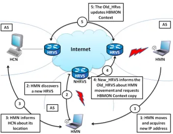
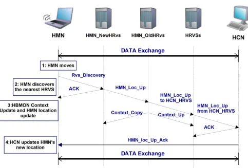
Figure 3 illustrates this mechanism through an example where a HBMON overlay is established between a HBMON mobile node (HMN) and a HBMON correspondent node (HCN), HMN and HCN have an ongoing communication and the HMN moves to another AS. This first strategy is an enhanced version of the HIP mobility management presented in Nikander et al. (2008). HIP mobility management as detail in Nikander et al. (2008) is an end-to-end readdressing procedure and does not take into account any proxy element (such as HIP RVS) in its specification. The Regular HBMON mobility adds to the HIP mobility management procedure the ability to store the HIP context in the HIP RVS. This context can then be retrieved by any HMN’s newly discovered RVS. Figure 4 presents the sequence diagram of the exchanged signalling messages for this strategy.
When the HMN moves and acquires a new topologically correct IP address (step 1 Figure 3), it sends an RVS Discovery message containing the old HBMON RVS’s (HRVS’s) IP address and its HIT (step 2 Figure 3). The RVS Discovery message is sent to a specific anycast address in order to discover the nearest HBMON RVS (NHRVS). After that, the HMN reports its new IP address to its HCNs using the HIP mobility mechanism; as explained in section 2.1.1 (step 4 Figure 3). The new RVS notifies the old HRVS about the new HMN location and triggers the HBMON context update by sending the Context Req message (step 3 Figure 3). Once the old HRVS receives a Context Req message, it updates the mapping between the HMN’s HIT and its new
Figure 3: Regular HBMON mobility scenario
IP address. Afterwards, it updates the HBMON context forwarding to all HBMON RVS the Context Update message (step 5 Figure 3). This message is sent on specific multicast address including all HBMON RVSs.
3.2.2 2ndstrategy: Lightweight HBMON mobility
We assume an established HBMON overlay between HMN and HCN, HMN is reg-istered with HMN HRvs and HCN is regreg-istered with HCN HRvs. We also assume that HMN and HCN have already an established session. We name this 2nd strategy lightweight HBMON mobility, in contrast to the regular HBMON mobility, as we com-bine Location Update and Context Update packets into a single message. Furthermore, unlike the first strategy, the second strategy is not based on the regular HIP mobility management presented in Nikander et al. (2008). Figure 5 describes this scenario and the sequence diagram of this mechanism is presented in Figure 5.
Once the HMN changes its point of attachment and acquires a new IP address (step 1 Figure 5), it sends an RVS Discovery message to discover the nearest RVS and registers with it (step 2 Figure 5). The RVS Discovery message includes also a new field containing the HCN’s HIT. The NHRVS sends then HMN Loc Up message to notify the HCNs about the new HMN’s IP address and update the HBMON context in the old RVS (step 3 Figure 5). At this stage, the old RVS lookups the NHRVS IP address and sends it the HMN loc Up packet(step 4 Figure 5). Meanwhile, the Old HRVS updates the HBMON context (step 4 Figure 5). The context update message is sent on multicast address. In the final stage, the HCN RVS notifies the HCN node of the HMN’s new IP address (step 5 Figure 5). The main advantage of this solution compared to the previous one is that it minimises the control packets with the merge of Location Update packets and Context Update packets into a single packet.
Figure 4: Regular HBMON mobility sequence diagram
Figure 6: Lightweight HBMON mobility sequence diagram
4
Signalling cost analysis
In this section, we propose an analytical model to assess the signalling cost of our two strategies. Tab.I gives notations that will be used.
As wireless link cost is higher than wired link cost, the transmission cost between a node and HRVS is equal to:
ΨN−R= lwδ+ (lnr− lw)ρδ.
where(lnr− lw) is the number of wireless links. The transmission cost between HRVS
and HRVS is equal to:
ΨR−R= lrrδ
4.1
RHM signalling cost
The RHM signalling cost depends on the following costs:
4.1.1 HRVS-Discovery cost
Once a HMN moves to another AS (happens every ⊤AS), it sends an RVS Discovery
packet to discover the nearest RVS (NHRVS). Thus, an RVS Discovery packet cost is the sum of the transmission cost between HMN and HRVS and the processing cost at all the HRVSs in the AS. The average RVS Discovery packet cost per second in the whole system can be estimated as the number of HMNs multiplied by the RVS Discovery
Parameter Definition
N Total number of HBMON member
NHMN Total number of HBMON mobile nodes (HMN)
NHRV S Total number of HBMON RVS(HRVS)
NNHRV S Total number of new HRVS of HMN
NHCN Avg. number of HCN communicating with a HMN
θHRV S Proportionality constant of the number of HRVS per the number of HBMON member
θNHRV S Proportionality constant of the number of NHRVS per the number of HMN
S Number of session λsa Avg. session arrival rate
λpa Avg. packet arrival rate
ϕ Avg. number of session-mobilityϕ= λsa∗ λpa(little theorem)
⊤AS Avg. AS residence time of node
γn Processing cost in a node
γr Processing cost in a RVS
lnr Avg. number of link between node and HRVS
lmc Avg. number of link between HMN and HCN
lw Avg. number of wired link between node and HRVS
lrr Avg. number of link between HRVS and HRVS
δ Per-hop message transmission cost over wired link
ρ Proportionality constant of the transmission cost over wired and wireless link ΨN−R Transmission cost between a node and HRVS
ΨR−R Transmission cost between two HRVS
Variables for RHM only ΦTot
RHM Regular HBMON Mobility signalling cost
ΦHrvsD
RHM Rendez-vous Discovery signalling cost
ΦUP1
RHM update1 (peer) signalling cost
ΨUP1
RHM update1 (peer) transmission cost
ΦUPRHM2 Req update2 (peer)-Req signalling cost ΨUPRHM2 Req update2 (peer)-Req transmission cost ΦUPRHM3 Resp update3 (peer)-Resp signalling cost ΨUPRHM3 Resp update3 (peer)-resp transmission cost ΦCReqRHM Context Request signalling cost ΨCReqRHM Context Request transmission cost ΦCRespRHM Context Response signalling cost ΨCRespRHM Context Response transmission cost ΦCU pRHM Context Update signalling cost ΨCU pRHM Context Update transmission cost ΦLU
RHM Lookup cost
Variables for LHM only ΦTot
LHM Lightweight HBMON Mobility signalling cost
ΦHrvsD
LHM Rendez-vous Discovery signalling cost
ΦMN LU
LHM HMN location update signalling cost
ΨMN LU
LHM HMN location update transmission cost
ΦCC
LHM Context Copy signalling cost
ΨCC
LHM Context Copy transmission cost
ΦCU pLHM Context Update signalling cost ΨCU pLHM Context Update transmission cost ΦLU Lookup cost
packet cost for each HMN, divided by the average AS residence time, ⊤AS, of the node: ΦHRV SDRHM = NHMN (2ΨN−R+ γr) ⊤AS 4.1.2 update1(peer) cost
After discovering the nearest RVS, a HMN sends the update1(peer) packet towards all its HCNs to update its location. The update1(peer) cost includes the transmission cost and the processing cost of the update location at all HCNs. Thus, the average update1(peer) cost per second in the whole system can be calculated by multiplying the number of HMNs and the average number of communicating HCNs by the up-date1(peer) cost divided by the average AS residence time, ⊤AS, of node :
ΦUPRHM1 = NHMNNHCN(ΨUP1+ γn)
⊤AS
Therefore, the update1(peer) transmission cost is the sum of the transmission cost between node and HRVS and the transmission cost between HRVS and HRVS:
ΨRHM= ΨN−R+ ΨR−R
4.1.3 update2(peer)-Req cost
After receiving an update1(peer) packet, each HCN communicating with HMN sends the update2(peer)-Req packet in order to check the new address of the HMN. Unlike update1(peer) cost, processing time costs are not included into the total signalling cost as they are processed at the end terminals. Thus,
ΦUPRHM2 Req= NHMNNHCN
ΨUP2
⊤AS
Like the update1(peer) transmission cost, the update2(peer)-Req transmission cost is equal to:
ΨUP2= ΨN−R+ ΨR−R
4.1.4 update3(peer)-Resp cost
Once an HMN receives the second update packet, it sends the update3(peer)-Resp to definitively validate the new address to all HCNs. Like update2(peer)-Req cost, pro-cessing time costs are not consider and the average update3(peer)-Resp cost in the whole is can be calculated as:
ΦUPRHM3 Resp= NHMNNHCN
ΨUP3
⊤AS
Where the update3(peer)-Resp transmission cost is equal to: ΨUP3= ΨN−R+ ΨR−R
4.1.5 Context Request cost
When the nearest HRVS receives the Rvs Discovery packet, it has to request the HB-MON context from the old HRVS. Thus, The Context Request cost includes the trans-mission cost and the processing cost at all HRVS. Context Request cost is equal to:
ΦCReqRHM= NHMN
(ΨR−R+ γr)
⊤AS
4.1.6 Context Response cost
Each old HRVS sends the HBMON context to the new HRVS discovered by HMN. Thus, the Context Response cost includes the transmission cost and the processing cost at all HRVS. The average Context Response cost in the whole system cost is equal to:
ΦCRespRHM = NHMN
(ΨR−R+ γr)
⊤AS
4.1.7 Context Update cost
In order to update the HBMON context, the old HRVS notifies all HRVS, forwarding the context update, about the HBMON context modification. So, the Context Response cost includes the transmission cost and the processing cost at all HRVS. The average Context Response cost can be estimated as:
ΦCReqRHM= NHMNNHCN
(NHRV S− (NNHRV S+ 1))(ΨR−R+ γr)
⊤AS
4.1.8 Lookup cost
We assume that HRVS database lookup cost has a linear relationship with NHMNhaving
ε as the linear coefficient, and the average session duration time is λsa
S . Thus, the
average lookup cost is equal to:
ΨLUDJ= NHMN2 NHCN
ελsa
S
4.1.9 The total signalling cost of RHM
The total signalling cost of RHM is the sum of all RHM signalling packets cost (see Eq. 1). ΦTotRHM= ΦHrvsDRHM + ΦUPRHM1 + Φ UP2 Req RHM + Φ UP3 Resp RHM (1) +ΦCReqRHM+ ΦCRespRHM + ΦCU pRHM+ ΦLU RHM.
4.2
LHM signalling cost
4.2.1 HRVS-Discovery cost
Like in RHM signalling cost, the average HRVS Discovery packet cost per second in the whole system is calculated as:
ΦHRV SDLHM = NHMN2 ∗ ΨN−R
+ γr
⊤AS
4.2.2 HMN location update cost
The NHRVS triggers the HMN location update packet, after receiving the HRVS Discovery packet, towards the old HRVS of HMN. Then, the old HRVS sends the location update packet to the HCNs via their HRVs. Thus, the average HMN location update cost per second in the whole system is estimated as:
ΦHMN LULHM = NHMN
(1 + NHCN)ΨR−R+ NHCNΨN−R+ (1 + NHCN)γr
⊤AS
+NHMNNHCN⊤ γn AS
4.2.3 Context Copy cost
Once the old HRVS receives the location update packet, it sends a HBMON context copy to the NHRVS. The Context Copy cost includes the transmission cost and the processing cost at NHRVS. So, the average Context Copy cost in the whole system is equal to:
ΦCC= NHMN
(ΨR−R+ γr)
⊤AS
4.2.4 Context Update cost
Furthermore, the old HRVS of HMN forwards on multicast address the Context Update to all HRVSs except the NHRVSs in order to update the HBMON context. Thus, the Context Update cost is the sum of the transmission cost and the processing cost at all HRVSs. The average Context Update cost in the whole system is given by:
ΦCU p= NHMN
(NHRV S− (NNHRV S+ 1))(ΨR−R+ γr)
⊤AS
4.2.5 Lookup cost
Like in RHM, the average lookup cost can be calculated as: ΦLULHM= N2
HMNNHCN
ελsa
S
4.2.6 The total signalling cost of LHM
Thus, the total signalling cost of LHM is given by Eq. 2: ΦTotLHM= ΦHrvsDLHM + ΦHMN LULHM + ΦCCLHM+ Φ
CU p LHM+ Φ
LU
4.3
Results
In the following, we compare the signalling cost of LHM and RHM. For all numerical calculations, we use the following parameter values used in Reaz et al. (2006) lnr=
35,lw= 10,lrr= 35,S= 10,λsa= 0.01,δ= 0.2,ρ= 10,ε= 0.3. Furthermore, we assume that the HMN moves according to the Random Waypoint model Bettstetter et al. (2004).
4.3.1 Impact of the number of HMN for different number of HRVS
Figure 7 shows the impact of the number of HMN on the signalling cost of RHM (Eq. 1) and LHM (Eq. 2) while varying the number of HRVS relatively to the num-ber of HBMON memnum-bers. We varyθ, the proportionality constant of the number of HRVS per number of HBMON members, from 10 to 40%. We set the total number of HBMON members N to 200, the average number of HCN NHCN to 5, the number
of new HRVS NNHRV S to 5 and the AS residence time TAS to 120s. From Figure 7,
we notice that both RHM and LHM signalling cost increase with the increase of the number of HBMON mobile nodes and the number of HRVS. We clearly see that the RHM strategy is sensitive to the increase in the proportionality constant of the number of HRVS per number of HBMON members; whereas, this is not the case of the LHM strategy. For a lower proportionality constant (10%), RHM and LHM have the same order of magnitude of the signalling cost. However, for a high proportionality constant (40%), RHM requires a signalling cost at least three time the signalling cost of LHM.
0 2000 4000 6000 8000 10000 12000 0 20 40 60 80 100 Signaling Cost Number of HMN LHM:HRvs=10% N RHM:HRvs=10% N LHM:HRvs=40% N RHM:HRvs=40% N
Figure 7: Signalling cost for RHM and LHM vs. number of HMN for different number of HRVS
4.3.2 Impact of the number of HMN for different number of average HCN Figure 8 highlights the variation of the signalling cost of RHM (Eq. 1) and LHM (Eq. 2) with the number of HMN while varying the average number of HCN. We set the total number of HBMON members N to 200, the number of HRVS NHRV Sto 20 (that is 10%
of N), the number of new HRVS NNHRV S to 5 and the AS residence time TASto 120s.
We can clearly see that the RHM strategy has higher signalling cost than that of LHM. This is explained by the fact that RHM requires extra location update packets; whereas, location update packets in LHM are merged within HBMON context update packets.
0 10000 20000 30000 40000 50000 0 20 40 60 80 100 Signaling Cost Number of HMN LHM:HCN=10% HMN RHM:HCN=10% HMN LHM:HCN=20% HMN RHM:HCN=20% HMN LHM:HCN=30% HMN RHM:HCN=30% HMN LHM:HCN=40% HMN RHM:HCN=40% HMN
Figure 8: Signalling cost for RHM and LHM vs. number of HMN for different number of average HCN
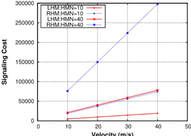
4.3.3 Impact of the HMN velocity for different number of HMN
Based on the random waypoint mobility modelBettstetter et al. (2004), we analyze the impact of HMN velocity on the signalling cost of RHM (Eq. 1) and LHM (Eq. 2) for different number of HMN. We use the following values: N=200, NHRV S=20 (that is
10% of N), NHCN=5 and NNHRV S=5. Figure 9 shows a clear correlation between the
ve-locity and the signalling cost. For high speeds, the TASdecreases and the signalling cost
increases. This is expected since higher velocity results into frequent L3 handovers. In summary, from the above results, we notice that the signalling cost of RHM is always higher than that of LHM. LHM does not rely on the HIP mobility extension to update location, it relays on HBMON context packet relayed through HIP Rendez-vous servers. RHM is not adapted for the M2M context where the number of the devices may outnumber by several order of magnitude the number of human users. We clearly see that LHM does not introduce any signalling storm and thus is more adapted than RHM to the M2M context.
5
Performance Evaluation
In this section, we present a performance evaluation of our HBMON mobility solution. We implement our HBMON mobility solution on the OMNeT++ simulator coupled with the HIPSim++ framework Bokor et al. (2009). We set all the wireless accesses to 802.11b at 11Mbit/s. In our scenario, we configure two M2M devices: HMN1 and
0 50000 100000 150000 200000 250000 300000 0 10 20 30 40 50 Signaling Cost Velocity (m/s) LHM:HMN=10 RHM:HMN=10 LHM:HMN=40 RHM:HMN=40
Figure 9: Signalling cost for RHM and LHM vs. HMN velocity for different number of HMN
HMN2, registered respectively with HRVS1 and HRVS2. HMN1 has a 802.11b inter-face associated with access point AP1 and HMN2 has a 802.11b interinter-face registered with access point AP2. HMN1 is a static node; whereas, HMN2 is a moving according to the random waypoint model. In our implementation we assume that for each net-work interface is configured with a single IP address. Therefore we use the single SA pair scheme to set up the HIP mobility mechanism (detailed in section 2.1.1). HMN1 and HMN2 exchange a 1 Mbit/s UDP traffic. We load the visited network with three nodes, each of them generating a UDP traffic at 1 Mbit/s. In our simulation, we mea-sured the Application Recovery Time (ART) which is the latency elapsed between the last packet sent with the old IP address and the first packet sent with the new IP address. The histogram presented in Figure 10 illustrates the measured ART for both RH and LHM for an empty and loaded visited network.
0 1 2 3 4 5 6 7 8 9 RHM LHM RHM LHM Time (s) L2 handover RVS_Discovery HBMON_Context_UpdateLocation_Update Loaded_cell Empty_cell
The ART latency is decomposed into 4 phases: (i) L2 handover, (ii) RVS Discovery, (iii) HBMON Context Update and (iv) Location Update. In an empty visited network, for both RHM and LHM strategies, the L2 handover latency is 0.65s, the RVS Discovery latency is 0.2s. However, for RHM strategy the HBMON Context Update latency is 1.7s and the Location Update latency is 1.05s; whereas, in the case of LHM these latencies are respectively 1.4s and 0.95s. These differences are mainly explained by the fact that in RHM, the HMN is in charge of notifying its corresponding HCN about its new location; whereas, in LHM this notification is sent within the update of the context update and is simply forwarder by the rendez-vous server of the HCN. In a loaded visited network, for both RHM and LHM strategies, the L2 handover latency is 0.819s, the RVS Discovery latency is 0.4s. However, for RHM strategy the HBMON Context Update latency is 2.3s and the Location Update latency is 1.4s; whereas, in the case of LHM these latencies are respectively 2s and 1.2s. The differ-ence between the two measured latencies is mainly due to layer 2 contention to access the wireless medium. We observe that with our solution, the running session effectively resumes after the mobility episode. The mobility signalling lasts more than 2.5s for the case of LHM in an empty visited network (the best measured case) which is inade-quate for real time applications. Nonetheless, M2M applications are usually low data-rate application, and providing session survivability - even after 2.5s of interruption- is preferable than completely losing the currently ongoing session.
6
Conclusion
In a previous work Dhraief et al. (2012), we have designed a HIP-based M2M over-lay network over the existing Internet. This overover-lay ensures a private communication between M2M devices and their corresponding M2M applications. The HIP protocol natively handles the regular mobility case. Nonetheless, we have analytically demon-strated in this paper that the regular HIP mobility management has a high signalling costs. We have therefore proposed a lightweight solution to handle the mobility of M2M devices within our overlay network. We have developed an analytic model for our solution and we have assessed the signalling cost based on the Random Waypoint Mobility model. Our analysis showed that our solution efficiently handles the mobility within our M2M overlay network without causing a signalling storm. We have imple-mented our solution on the OMNeT++ simulator in order to measure the application recovery time in both cases of empty and loaded visited network. Results showed that M2M devices running sessions survive to mobility episodes.
Acknowledgment
References
Bettstetter, C., Hartenstein, H., and Perez-Costa, X. (2004) ’Stochastic properties of the random waypoint mobility model’, Wireless Networks, Vol.10 No.5, pp.555-567.
Bokor, L., Nov´aczki, S., Zeke, L. T., and Jeney, G. (2009) ’Design and evaluation of host identity protocol (hip) simulation framework for inet/omnet++’, In MSWiM ’09: Proceedings of the
12th ACM international conference on Modeling, analysis and simulation of wireless and
mobile systems, Tenerife, Canary Islands, Spain, pp. 124-133.
Dhraief, A., Belghith, A., Drira, K., Bouali, T., and Ghorbali, M. A. (2013a) ’Autonomic man-agement of the HIP-Based M2M overlay network’, In ANT’13: The 4th International
Con-ference on Ambient Systems, Networks and Technologies, Halifax, Nova Scotia, Canada,
pp. 98-105.
Dhraief, A., Ghorbali, M., Bouali, T., Belghith, A., and Drira, K. (2013b) ’Simultaneous mobil-ity management in the HIP-based M2M overlay Network’, In IWCMC’13: The 9th IEEE
International Wireless Communications and Mobile Computing Conference, Cagliari,
Sar-dinia , Italy.
Dhraief, A., Ghorbali, M. A., Bouali, T., Belghith, A., and Drira, K. (2012) ’HBMON: A Hip Based M2M Overlay Network’, In Network of the Future (NOF), 2012 Third International
Conference on the, Tunis, Tunisia, pp. 1-8.
Dhraief, A. and Montavont, N. (2009) ’Rehoming decision algorithm: Design and empirical evaluation’, In Computational Science and Engineering, 2009. CSE ’09. International
Con-ference on, Vol.2, Vancouver, BC, Canada, pp. 464-469.
Daniel Minoli. (2013) ’Layer 3 Connectivity: Mobile IPv6 Technologies for the IoT, in Building the Internet of Things with IPv6 and MIPv6: The Evolving World of M2M Communica-tions,’, John Wiley & Sons Inc., pp. 257-292.
ETSI Technical Committee Machine-to-Machine communications (M2M) (2011) ’Machine-to-Machine communications (M2M); Functional architecture’. TS 102 690.
Fadlullah, Z., Fouda, M., Kato, N., Takeuchi, A., Iwasaki, N., and Nozaki, Y. (2011) ’Toward in-telligent machine-to-machine communications in smart grid’, Communications Magazine,
IEEE, Vol.49 No.4, pp. 60-65.
Henderson, T. R., Ahrenholz, J. M., and Kim, J. H. (2003) ’Experience with the host identity protocol for secure host mobility and multihoming’, WCNC 2003: IEEE Wireless
Commu-nications and Networking, New Orleans, LA, USA, pp. 2120-2125.
Juniper Networks (2011) ’Machine-to-Machine (M2M) The Rise of the Machines’. white paper. Laganier, J. and Eggert, L. (2008) ’Host Identity Protocol (HIP) Rendezvous Extension’, RFC
5204 (Experimental).
Lu, R., Li, X., Liang, X., Shen, X., and Lin, X. (2011) ’GRS: The green, reliability, and security of emerging machine to machine communications’, Communications Magazine, IEEE, Vol.49 No.4, pp. 28-35.
Moskowitz, R. and Nikander, P. (2006) ’Host Identity Protocol (HIP) Architecture’. RFC 4423 (Informational).
Moskowitz, R., Nikander, P., Jokela, P., and Henderson, T. (2008) ’Host Identity Protocol’, RFC 5201 (Experimental) Updated by RFC 6253.
Nikander, P., Henderson, T., Vogt, C., and Arkko, J. (2008) End-Host Mobility and Multihoming with the Host Identity Protocol. RFC 5206 (Experimental).
Reaz, A. S., Chowdhury, P. K., Atiquzzaman, M., and Ivancic, W. (2006) ’Signalling cost analysis of sinemo: seamless end-to-end network mobility’, In MobiArch ’06: Proceedings
of first ACM/IEEE international workshop on Mobility in the evolving internet architecture,
San Francisco, California, USA, pp. 37-42.
Uusitalo, M. A. (2006) ’Global vision for the future wireless world from the WWRF’, Vehicular
Technology Magazine, IEEE, Vol.1 No.2, pp. 4-8.
Wong, K. D. and Woon, W. L. (2007) ’Simultaneous Mobility: A New Analytical Approach’, In Vehicular Technology Conference, 2007. VTC2007-Spring. IEEE 65th, Dublin, Ireland, pp. 884-888.
Wu, G., Talwar, S., Johnsson, K., Himayat, N., and Johnson, K. (2011) ’M2M: From mobile to embedded internet’, Communications Magazine, IEEE, Vol.49 No.4, pp. 36-43.
Zhang, Y., Yu, R., Xie, S., Yao, W., Xiao, Y., and Guizani, M. (2011) ’Home M2M networks: Ar-chitectures, standards, and QoS improvement’, Communications Magazine, IEEE, Vol.49 No.4, pp. 44-52.