READ THESE TERMS AND CONDITIONS CAREFULLY BEFORE USING THIS WEBSITE. https://nrc-publications.canada.ca/eng/copyright
Vous avez des questions? Nous pouvons vous aider. Pour communiquer directement avec un auteur, consultez la première page de la revue dans laquelle son article a été publié afin de trouver ses coordonnées. Si vous n’arrivez pas à les repérer, communiquez avec nous à [email protected].
Questions? Contact the NRC Publications Archive team at
[email protected]. If you wish to email the authors directly, please see the first page of the publication for their contact information.
NRC Publications Archive
Archives des publications du CNRC
This publication could be one of several versions: author’s original, accepted manuscript or the publisher’s version. / La version de cette publication peut être l’une des suivantes : la version prépublication de l’auteur, la version acceptée du manuscrit ou la version de l’éditeur.
Access and use of this website and the material on it are subject to the Terms and Conditions set forth at
Affordable 3D Face Tracking using Projective Vision
Gorodnichy, Dimitry; Malik, S.; Roth, Gerhard
https://publications-cnrc.canada.ca/fra/droits
L’accès à ce site Web et l’utilisation de son contenu sont assujettis aux conditions présentées dans le site LISEZ CES CONDITIONS ATTENTIVEMENT AVANT D’UTILISER CE SITE WEB.
NRC Publications Record / Notice d'Archives des publications de CNRC:
https://nrc-publications.canada.ca/eng/view/object/?id=de163ca9-b2b3-422d-90d7-b6c9d1d6478d https://publications-cnrc.canada.ca/fra/voir/objet/?id=de163ca9-b2b3-422d-90d7-b6c9d1d6478d
National Research Council Canada Institute for Information Technology Conseil national de recherches Canada Institut de technologie de l'information
Affordable 3D Face Tracking using
Projective Vision *
Gorodnichy, D., Malik, S., and Roth, G.
May 2002
* published in Vision Interface 2002, pp. 383-390. Calgary, Alberta, Canada. May 2002. NRC 45862.
Copyright 2002 by
National Research Council of Canada
Permission is granted to quote short excerpts and to reproduce figures and tables from this report, provided that the source of such material is fully acknowledged.
Affordable 3D Face Tracking Using Projective Vision
D.O. Gorodnichy
✁✄✂, S. Malik
☎, G. Roth
✁ ✁Computational Video Group, National Research Council, Ottawa, Canada K1A 0R6
☎
School of Computer Science, Carleton University, Ottawa, Canada, K1S 5B6
http://www.cv.iit.nrc.ca/research/Stereotracker
Abstract
For humans, to view a scene with two eyes is clearly more advantageous than to do that with one eye. In computer vi-sion however, most of high-level vivi-sion tasks, an example of which is face tracking, are still done with one camera only. This is due to the fact that, unlike in human brains, the rela-tionship between the images observed by two arbitrary video cameras, in many cases, is not known. Recent advances in projective vision theory however have produced the method-ology which allows one to compute this relationship. This relationship is naturally obtained while observing the same scene with both cameras and knowing this relationship not only makes it possible to track features in 3D, but also makes tracking much more robust and precise. In this paper, we es-tablish a framework based on projective vision for tracking faces in 3D using two arbitrary cameras, and describe a stereo tracking system, which uses the proposed framework to track faces in 3D with the aid of two USB cameras. While being very affordable, our stereotracker exhibits pixel size precision and is robust to head’s rotation in all three axis of rotation.
1
Introduction
We consider the problem of tracking faces using a video camera and focus our attention on the design of the vision-based perceptual user interface systems [28]. The main applications of these systems are seen in HCI, teleconfer-encing, entertainment, security and industry for disabled [27, 30].
Being a high-level vision problem, face tracking prob-lem poses four major challenges: robustness, precision, speed and affordability. While the last two have become much less critical over the last few years due to the signif-icant increase of computer power and decrease of camera cost, the first two remain unresolved.
The approaches to face tracking can be divided into two classes: global (image-based) and local (feature-based)
ap-✆
In Proc. Intern. Conf. on Vision Interface (VI’2002), pp. 383-390, Calgary, May 27-29, 2002 (http://www.visioninterface.org/vi2002).
✝
The author the correspondence should be sent to.
proaches [10, 31]. Global approaches use global cues like skin colour, head geometry and motion, are more robust, but cannot be used for pixel-size precision tracking. On the other hand, local approaches, which are based on track-ing facial features, can theoretically track very precisely. In practice however they do not, because they are very unro-bust, due to the variety of motions and expressions a face may exhibit.
While for humans it is definitely easier to track objects with two eyes than with one eye, in computer vision face tracking is usually done with one camera only. A few au-thors do use stereo for face tracking [14, 15, 20, 29]. They however use the second camera mainly for the purpose of acquiring the third dimension rather than making tracking more robust, precise or affordable. In fact, conventional stereo setups are usually precalibrated and quite expensive.
The problem is that human brain knows and makes use of the relationship between the images while processing them [2, 3], while computers do not. Recent advances in computer vision though provided the methodology based on projective vision that allows one to compute this relationship for any two cameras [9, 23]. This relationship is naturally obtained while observing the same scene with both cameras and is represented by the fundamental matrix which relates the two images to one another.
This paper describes how to use the projective vision techniques for tracking faces with two arbitrary cameras. The most significant result is that computing the fundamen-tal matrix not only allows one to recover the 3D position of the object with low-cost cameras, but also makes track-ing much more robust. Combintrack-ing the proposed projective-vision-based tracking approach with the robust convex-shape nose tracking technique described in [5] allowed us to build a stereo tracking system, which is able to track faces in 3D using two generic USB cameras. The robustness of the system, the binary code of which can be downloaded from our website, is such that the rotations of a head of up to 40 degrees in all three axis of rotation can be tracked.
The paper is organized as follows. After presenting the outline of our framework for affordable stereotracking (Section 2), we recap the projective vision properties which make the framework possible (Section 3). This is followed
x z
Figure 1:Stereo tracking with two web-cameras. The key issue is finding the relationship between the cameras.
by the description of the stereo selfcalibration procedure (Section 4). Then we describe the tracking procedure of the framework and present the experimental results (Section 5).
2
Stereo system setup
In order to present a framework for doing stereo tracking with two arbitrary uncalibrated cameras, we will describe the StereoTracker developed by our group, where this frame-work is implemented.
The StereoTracker allows a user to do high-level vi-sion tasks with off-the-shelf vivi-sion equipment. It tracks the face of a user in 3D with the aid of two ordinary USB web-cameras and consists of three major modules: 1) stereo self-calibration, 2) facial features learning and 3) feature track-ing. The setup of the system is the followtrack-ing.
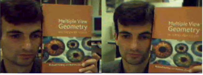
A user mounts two USB cameras on the top of the com-puter monitor so that his face is seen by both cameras (see Figure 1), after which the user runs the selfcalibration mod-ule of the StereoTracker to acquire the relationship between the cameras. For this the user captures his head at the same time with both cameras at the distance to be used in track-ing (Figure 2). When the stereo calibration information has been calculated, the StereoTracker makes use of it to learn robust facial features (Figure 3), and then makes use of it again while tracking the features in 3D (Figure 4).
Before proceeding to the description of the calibration procedure, which is the basis of our stereotracking frame-work, we need to describe notations and properties to be used throughout the paper.
3
Projective vision interlude
3.1
Points, lines and calibration matrix.
According to the projective paradigm, every 2D pixel✞✠✟ ✡☛✌☞✎✍✑✏✓✒
of an image is as associated with the 3D vector✔✕✟ ✡✖✗☞✙✘✚☞✄✛✄✏
✒
which starts at the camera origin and goes though to all 3D space points which are projected to the same pixel
on the image plane.1 A line in an image is represented by
3D vector✜ which is perpendicular to all points✔ belonging
to the line:✜
✒
✔✢✟✤✣ .
The relationship between vector✔ and pixel position✥
of a point in the image is expressed as
✔✦✟★✧★✩✞✫✪ (1)
where✞✩ denotes a 3D vector obtained from a 2D vector✞
by adding one as the last element. Matrix K in this equation, the simplified form of which is written below, is termed the
calibration matrix of the camera. It describes the intrinsic
parameters of the camera, the most important of which are the center of the image ✬
☛✎✭✮☞✯✍✰✭✲✱
measured in pixel coordi-nates, and the focal length of the camera✳ , defined as the
distance from the camera origin to the camera image plane measured in pixels: ✧✴✟ ✵✶ ✳ ✣ ☛✭ ✣ ✳ ✍ ✭ ✣ ✣ ✛ ✷✸ ✪ (2)
Computing the calibration matrix of the camera consti-tutes the calibration process of the camera. The goal of self-calibration is to compute this matrix directly from an im-age sequence without resorting to a formal calibration pro-cedure. One of the ways to do this is by using the concept of the fundamental matrix.
3.2
Stereo and fundamental matrix
When a 3D point✹ in space is observed by two cameras,
it is projected to the image plane of each camera. This gen-erates two vectors✔ and✔✻✺ starting from the origin of each
camera. These vectors are related to each other through the equation ✔ ✒✗✼✾✽❀✿ ✔ ✺ ✟★✣ ☞ (3) where ✼
is the translation vector between the camera posi-tions and
✿
is the rotation matrix. This equation simply states the fact vectors✔ ,
✼
and✔✻✺ are coplanar. In computer
vision, this equation is known as the epipolar constraint and is usually written as ✔ ✒❂❁ ✔ ✺ ✟✤✣ ☞ where (4) ❁❄❃ ✼❅✽❆✿
is termed the essential matrix✪ (5)
The epipolar constraint holds for any two camera setup and is very important for 3D applications, as it defines the relationship between the corresponding points in two cam-era images. For hand made stereo setup with off-the-shelf
1Some authors [11, 8] prefer using vector
❇❈❊❉●❋✑❉✎❍✲■❑❏ instead of ❇❈❊❉●❋▲❉
✁
Figure 2:Images captured by two cameras to be used in selfcali-bration. They should have enough visual features.
cameras,
✼
and
✿
are not known. If the cameras are uncali-brated, then matrix ✧ is not known either. In this case, the
epipolar constraint is rewritten, using Eq. 1, as
✩✞ ✒✗▼ ✩ ✞◆✟✤✣ (6) where✞❖✟✩ ✡ ✥ ☞◗P❘☞✰✛❙✏✓✒ and✞❂✺❚✟✩ ✡ ✥❯✺ ☞ ✥✚✺ ☞✰✛❙✏✓✒
define the raw pixel coordinates of the calibrated vectors✔ and✔✻✺, and
ma-trix ▼ defined as ▼ ❃ ✧ ❁ ✧ ✒ (7) is termed the fundamental matrix of the stereo.
Computing the fundamental matrix constitutes the cali-bration process of the stereo setup. Next section describes this process in detail for the case of low-quality cameras, and below we describe the properties of the fundamental matrix to be used in stereotracking.
3.3
Epipolar lines
Given a point✥ in one image, the fundamental matrix can
be used to compute a line in the other image on which the matching point must lie. This line is called the epipolar line and can be computed as
✜●❱❲✟
▼
✞❳✪ (8)
It is this piece of extra information that makes tracking with two cameras much more robust than tracking with one camera. In order to filter out bad matches, the epipolar
er-ror, defined as the sum of squares of distances of points to
their epipolar lines, can be used [9]. Using Eq. 8, the rela-tionship between epipolar error❨ and fundamental matrix
▼ can be derived as ❨ ❃★❩❭❬ ✬❪✞ ☞ ✜●❱▲❫ ✱✻❴ ❩ ✺ ❬ ✬❪✞✗✺ ☞ ✜❪❱ ✱ ✟❵✬●✞ ✺ ✒ ▼ ✞ ✱ ❬❘❛ ❜ ❝❡❞ ❱▲❢❤❣✐✙❥ ❝❦❞ ❱▲❢❤❣ ❣ ❴ ❜ ❝❦❞♠❧ ❱ ❫❢❤❣✐♥❥ ❝❦❞♠❧ ❱ ❫❢●❣ ❣❭♦ (9)
and the following proposition can be used to make tracking more robust.
Proposition: Provided that fundamental matrix
▼
of the stereo is known, the best pair of matches ✞ and ✞✗✺
corre-sponding to a 3D feature is the one that minimizes the epipo-lar error defined by Eq. 9.
4
Stereo system selfcalibration
The calibration procedure described below is implemented using the public domain Projective Vision Toolkit (PVT) [18] and is based on finding the correspondences in two images captured with both cameras observing at the same static scene. Because off-the-shelf USB cameras are usually of low quality and resolution, extra care is taken to deal with the bad matches by applying a set of filters and using robust statistics. The description of each step follows.
Finding interest points. After two images of the same
scene are taken, the first step is to find a set of corners or interest points in each image. These are the points where there is a significant change in intensity gradient in both the
✖
and
✘
direction. A local interest point operator [26] is used and a fixed number of corners is returned. The final results are not particularly sensitive to the number of corners. Typically there are in the order of 200 corners found in each image.
Matching corners and symmetry filter. The next step
is to match corners between the images. A local window around each corner is correlated against all other corner windows in the adjacent image that are within a certain pixel distance [32]. This distance represents an upper bound on the maximum disparity and is set to 1/3 of the image size. All corner pairs that pass a minimum correlation threshold are then filtered using a symmetry test, which requires the correlation be maximum in both directions. This filters out half of the matches and forces the remaining matches to be one-to-one.
Disparity gradient filter.The next step is to perform local filtering of these matches. We use a relaxation-like process based on the concept of disparity gradient [12] which mea-sures the compatibility of two correspondences between an image pair. It is defined as the ratio
❩✮♣rq ✟ts✉✗✈①✇②✉✗③✗s④⑤s✉⑦⑥✙⑧✮⑨ ⑩ s ☞ (10) where✉ ✈ and✉ ③ are the disparity vectors of two corners, ✉❶⑥✙⑧✮⑨
⑩ is the vector that joins midpoints of these disparity
vectors, and s❸❷✚s designates the absolute value of a vector.
The smaller the disparity gradient, the more the two correspondences in agreement with each other. This filter is very efficient. At a very low computational cost, it removes a significant number of incorrect matches.
Using random sampling.The final step is to use the filtered matches to compute the fundamental matrix. This process must be robust, since it still can not be assumed that all fil-tered correspondences are correct. Robustness is achieved by using a random sampling algorithm. This is a “generate
and test” process in which a minimal set of correspondences, the smallest number necessary to define a unique fundamen-tal matrix (7 points), are randomly chosen [25, 22]. A fun-damental matrix is then computed from this best minimal set using Eq. 6. The set of all corners that satisfy this fun-damental matrix, in terms of Eq. 9, is called the support set. The fundamental matrix with the largest support set is used in stereotracking. Before it can be used however, it needs to be evaluated, because robust and precise tracking tracking is possible only under the assumptions that the computed fundamental matrix correctly represents the current stereo-setup.
4.1
Evaluating the quality of calibration
The evaluation is done using two ways: analytically - by examining the size of the support set, and visually - by visual examination of the epipolar lines.
It has been empirically obtained that for the fundamental matrix to be correct it should have at least 35 matches in the support set. If their number is less, it means that either i) there were not enough visual features present in the images, or ii) cameras are located too far from each other. In this case, cameras have to be repositioned or some extra objects, in addition to the head, should be added in the camera field of view and the calibration procedure should be repeated.
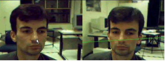
Figure 3 shows the epipolar line (on the right side) cor-responding to the tip of the nose (on the left side) as ob-tained for the stereo setup consisting of two Intel USB web-cams shown in Figure 1. As can be seen, it passes correctly through the nose, thus verifying the correctness of the funda-mental matrix and presenting a useful constraint for locating the nose in the tracking stage.
4.2
Finding the calibration matrix
Knowing matrix
▼
allows one to compute matrix✧ . Under
the assumptions that the intrinsic parameters of both cam-eras are the same, the approach we use is that of [17]. It is based on the fact that matrix
❁
, defined by Eq. 5 and re-lated to matrix
▼
through Eq. 7, has exactly two non-zero and equal eigenvalues. The idea is to find such calibration matrix ✧ that makes the two eigenvalues of
❁
as close as possible. Given two non zero eigenvalues of
❁ : ❹ ❜ and❹ ❬ (❹ ❜⑦❺ ❹ ❬
), consider the difference✬●❹
❜ ✇❻❹ ❬ ✱ ④❼❹ ❜ . Given a fundamental matrix
▼
, selfcalibration proceeds by finding such a calibration matrix that minimizes this dif-ference. This is an optimization problem which is solved by dynamic hill climbing gradient descent approach [16]. In [24] it is shown that this procedure, while quite simple, is not inferior to more complicated approaches to selfcalibra-tion, such as those using the Kruppa’s equation [13].
Knowing matrix✧ and the focal length allows one to
reconstruct spatial relationship of the observed features. For
Figure 3:Learning the features using the epipolar constraints. The nose feature must lie on the epipolar line.
the tracking process however, this information is not re-quired.
5
Stereo feature tracking
We use the pattern recognition paradigm to represent a fea-ture as a multi-dimensional vector made of feafea-ture attributes. In the case of image-based feature tracking, the feature at-tributes are the image intensities obtained by centering a specially designed peephole mask on the position of the fea-ture (as in [6]).
The major advantage of stereotracking, i.e. tracking with two cameras, over tracking with one camera is that of having an additional epipolar constraint which ensures that the ob-served features belong to a rigid body (see Section 3.3). Us-ing this constraint allows us to relax the matchUs-ing constraint used to enforce the visual similarity between the observed and the template feature vectors. The matching constraint is the main reason why feature-based tracking with one cam-era is not robust, and relaxing this constraint makes tracking much more robust.
5.1
Feature learning
In this work, we are not concerned with automatic detection of facial features. All features are manually chosen at the learning stage. During this stage, by clicking with a mouse a user selects a feature in one of the pair images (see Figure 3). This generates an epipolar line in the other image and the template vectors of both the selected feature and the best match of the feature in the other image lying on the epipo-lar line are stored. The examples of learnt templates can be seen in Figure 4 underneath the face images. By visually ex-amining the similarity of these templates, a user can ensure that the stereo setup is well calibrated and that the epipolar constraint indeed provides a useful constraint.
Several features can be selected for tracking. However one of these features must be the tip of the nose. The tip of the nose is a very unique and important feature. As shown in [5], due to its convex shape, this feature is invariant to both the rotation and the scale of the head. If detection of the face
orientation is not required, then robust face tracking in 3D can be achieved using this feature only.
Other features may include conventional edge-based fea-tures such as inner corners of the brows and corners of the mouth. At least two of these features are required in order to track the orientation of the head. These features are not invariant to the 3D motion of the head. Therefore, in or-der to make the tracking of these features robust, the rigid-ity constraint which relates their positions to the nose posi-tion is imposed. This constraint is computed while selecting the features. Another constraint used in stereotracking is the disparity constraint, which defines the allowable dispar-ity values for features during the tracking, thus limiting the area of search. Both the rigidity and the disparity constraints are computed during the selection of features in the learning stage and can be engaged or disengaged during the tracking.
5.2
Tracking procedure
Each selected facial feature is tracked using the following four-step procedure.
Step 1. The area for the local search is obtained using the rigidity constraint and the knowledge of the nose tip po-sition. When the rigidity constraint is not engaged or when the feature is the nose, the local search area is set around the previous position of the feature. If this knowledge is not available (as in the case of mistracking), then the search area is set to the entire image.
Step 2. A set of❽ best candidate matches❾✲✞✗❿✲➀ is
gen-erated in both images by using the peephole mask and cor-relating the local search area with template vector ➁
➂❯➃
learnt in the training. In order to be considered valid, all candi-date matches are required to have the correlation with the template feature larger than a certain threshold. In our ex-periments, the allowable minimum correlation is set to 0.9.
Step 3. Out of❽
❬
possible match pairs between two images, the best ➄ pairs are selected using the
cross-correlation between the images. In our experiments, ❽ is
set to 10 and➄ is set to 5. Increasing❽ or➄ increases the
processing time, but makes tracking more robust.
Step 4. Finally, the proposition of Section 3 is used and the match pair that minimizes the epipolar error ❨ defined
by Eq. 9, is returned by the stereo tracking system. If the re-turned match has the epipolar error less then a certain thresh-old, than the feature is considered successfully tracked. Oth-erwise, the feature is considered mistracked. The value of the maximum allowable epipolar error❨❭➅➇➆r➈ depends on the
quality of stereo selfcalibration and should be determined during the learning stage by observing the epipolar lines at different parts of the image. In the experiments presented in this paper it is set equal to 5 pixels.
When a feature is successfully tracked, its 3D position can be calculated using the essential matrix
❁
as in [9]. The distance between the cameras can be either measured
Figure 4:The StereoTracker at work. The orientation and scale of the virtual man (at the bottom right) is controlled by the position of the observed face.
by hand or set equal to one. In the latter case, the reconstruc-tion will be known up to a scale factor, which is sufficient for most applications
5.3
Experiments
The tracked facial features provide the information about the position and the orientation of the head with respect to the cameras. This information can be used to control a 2D object on the screen, such as a cursor or a turret in a aim-n-shoot game (as in [7]), or it can be used to control a 3D object, examples of which can be found in computer games and avatar-like computer-generated communication programs (as in [19]). The StereoTracker system, which we have developed, allows one to test the applicability of the proposed stereotracking technique to either of these appli-cations.
Figure 4 shows two images which are controlled by the motion of the head. The image on the bottom left is the re-projection of the detected features onto the 2D image plane. Our experiments show that by thinking of a nose as a point-ing device, one can easily pin-point to any pixels on the per-spective view screen. The system is robust to the rotation of the head. This makes it possible to draw a straight line with the nose, represented by the lowest vertex of the triangle in the figure, by simply rotating the head.
The user interface of the StereoTracker allows one also to change the perspective view of the features to the top-down. view. This is used to evaluate the potential of using the third dimension of the tracked features for controlling the size of a cursor or another virtual object on the screen. The image on the bottom right of Figure 4 shows a virtual man, the po-sition of which in a virtual 3D space is controlled by the
mo-tion of the user’s head; the scale of the man is propormo-tional to the distance between the features and the camera and the roll rotation of the man coincides with the roll rotation of the head.
Due to the robustness of the stereotracking, there is quite a wide range of head motion which can be tracked. For example, for the setup shown in Figure 1, the experiments show that within a range from 20 cm to 60 cm the head is tracked successfully. The tracking however become less ro-bust to the rotation of the head, as a user moves further from the original position.
Another observation is that stereotracking with low-quality cameras does not allow one to retrieve the pan and tilt rotation of the head. This however does not come as sur-prise, if we recall that the depth calculation error due to low resolution of the image can be as high as 10% of the mea-sured depth distance depending on the position of the feature [4, 21].
The user interface of the StereoTracker allows one to evaluate the robustness, speed and precision of stereotrack-ing with respect to the internal parameters and constraints of tracking. These parameters can be changed during the tracking stage and include already the mentioned minimum allowable correlation, the number of feature candidates (❽ ),
the number of refined matches after cross-correlation (➄ ),
maximum epipolar error, and also the size of the area for the subpixel refinement, which can be used for the features pos-sessing the continuity property (see [5]), and the maximum color difference between the stored feature pixel and a pixel being scanned. The last constraint is due to the fact that template matching in our system is done with black-n-white images; adding this constraint allows us to use the colour information to reduce the number of feature candidates.
In addition, the facial features can be checked in and out for tracking using the menu of the program. The disparity, rigidity and epipolar constraints can also be engaged and disengaged using the menu. While tracking is performed, the StereoTracker outputs statistics such as minimum and maximum values of correlation, cross-correlation and epipo-lar errors of the detected features as well as the detected 3D position and roll orientation of the head and the position of the cursor controlled by the head.
While the paper presents only the snapshots of our ex-periments, full MPEG videos of the StereoTracker at work are available at our website. The binary code of the program can also be downloaded from the website. In order to run it, a user will only have to have two USB webcams connected to a computer. In our experiments, we used two Intel USB web-cameras. Other USB webcams, such as Logitech, Cre-ative and 3Com, were also tried. Accessing the images is done using the DirectX interface. The resolution of the im-ages is 320 by 240. Lower resolution of 160 by 120 was also tried and found to be sufficient for precise and robust track-ing. Image smoothing is done using the Intel Open Source
CV library [1]. On a Pentium III 800 MHz processor, all processing takes 0.10 ms per frame in average. This allows one to do stereo face tracking in real time.
Figure 5 shows a typical range of head motion which is tracked using our framework along with the position of 2D and 3D objects controlled by the head motion: tilt motion (a), pan motion (b), roll motion (c), and motion further from the cameras (d). Yellow boxes around the features show the areas for local search of the facial features. Using three fea-tures is found most optimal for recovering the orientation of the head; inner corners of the brows being more prefer-able to track than corners of the mouth. Using five features slowed down the processing and often resulted in breaking the rigidity constraint. The figure shows well the precision and the robustness of stereo tracking. By switching on and off the epipolar constraint, we were able to observe that us-ing one camera does not allow one to detect features in the images like those shown in Figure 5.(c)(d), whereas using two cameras does. In a similar fashion, by switching on and off the rigidity constraint, we could see how stereotracking allows one to track robustly even such non-robust features as corners of the brows.
We have experimented with the different baselines be-tween the cameras, and the distance of about 10–20 cm ap-pears to be the most optimal. Larger baselines result in too few matches needed to compute the fundamental matrix, while smaller baselines cause large epipolar errors. It was also observed that the alignment of the cameras is not very critical for our framework, which is is attributed to using the rotation invariant convex-shape nose feature and the combi-nation of the epipolar constraint with the rigidity constraint.
6
Conclusions
In this paper we defined a framework for tracking faces in 3D using two generic web-cameras. The advantages of us-ing two cameras (two “eyes”) for face trackus-ing, as exhibited by our StereoTracker, are summarized below. One can track features:
1. In low quality images. – Low cost plug-n-play USB cam-eras are used.
2. More precisely, with sub-pixel accuracy. – One can move the screen cursor with his/her head one pixel at time on a 360x240 grid.
3. More robustly, with respect to scale and rotations. – Features are tracked for up to almost 40 degrees of rotation of head in all three directions: “yes”(up-down), “no”(left-right), and “don’t know” (clockwise).
4. In real time. – After two cameras have been calibrated, the work of tracking becomes simpler. Calibration can be done automatically, as soon as the head is seen in both cam-eras.
recovered.
Projective vision and robust statistics enable us to deal with uncalibrated cameras (i.e. cameras for which the in-trinsic parameters such as focal length, optical center etc. are not known), which are the most common cameras on the market. The gain in the accuracy and robustness is achieved by using two cameras where only one camera has been used in the past. It is thus believed that the proposed technol-ogy brings high-level computer vision solutions closer for the market.
References
[1] G. Bradski. OpenCV: Examples of use and new applications in stereo, recognition and tracking. In Proc. Intern. Conf. on
Vision Interface (VI’2002), Calgary, May 2002.
[2] D. Burr, M. Morrone, and L. Vaina. Large receptive fields for optic flow detectors in humans. Vision Research, 38(12):1731–1743, 1998.
[3] D. Gorodnichy. Investigation and design of high perfor-mance neural networks. PhD dissertation, Glushkov Cybernetics Center of Ac.Sc. of Ukraine in Kiev (http://www.cs.ualberta.ca/➉ ai/alumni/dmitri/PINN), 1997.
[4] D. Gorodnichy. Vision-based world modeling using a piece-wise linear representation of the occupancy function. PhD
dissertation, Computing Science Dept, University of Alberta (http://www.cs.ualberta.ca/➉ ai/alumni/dmitri/WorldModeling),
2000.
[5] D. Gorodnichy. On importance of nose for face tracking. In Proc. IEEE Intern. Conf. on Automatic Face and Gesture
Recognition (FG’2002), Washington, D.C., May 2002.
[6] D. Gorodnichy, W. Armstrong, and X. Li. Adaptive logic net-works for facial feature detection. In Proc. Intern. Conf. on
Image Analysis and Processing (ICIAP’97), Vol. II (LNCS, Vol. 1311), pp. 332-339, Springer, 1997.
[7] D. Gorodnichy, S. Malik, and G. Roth. Nouse ‘Use your nose as a mouse’ - a new technology for hands-free games and interfaces. In Proc. Intern. Conf. on Vision Interface
(VI’2002), pages 354–361, Calgary, May 2002.
[8] R. Hartley. In defence of the 8 point algorithm. IEEE
Trans-actions on Pattern Analysis and Machine Intelligence, 19(6),
1997.
[9] R. Hartley and A. Zisserman. Multiple view geometry in
computer vision. Cambridge Uinversity Press, 2000.
[10] E. Hjelmas and B. K. Low. Large receptive fields for op-tic flow detectors in humans. Computer Vision and Image
Understanding, 83:236 – 274, 2001.
[11] K. Kanatani. Geometric Computation for Machine Vision. Oxford University Press, 1993.
[12] R. Klette, K. Schluns, and A. Koschan. Computer Vision:
three-dimensional data from images. Springer, 1996.
[13] L. Lourakis and R. Deriche. Camera self-calibration using the svd of the fundamental matrix. Technical Report 3748, INRIA, August 1999.
[14] G. Loy, E. Holden, and R. Owens. 3D head tracker for an automatic lipreading system. In Proc. Australian Conf.
on Robotics and Automation (ACRA2000), Melbourne,
Aus-tralia, August 2000.
[15] Y. Matsumoto and A. Zelinsky. An algorithm for real-time stereo vision implementation of head pose and gaze direc-tion measurement. In Proc. IEEE Intern. Conf. on Automatic
Face and Gesture Recognition (FG2000), 2000.
[16] M. Maza and D. Yuret. Dynamic hill climbing. AI Expert, pages 26–31, 1994.
[17] P. Mendonca and R. Cipolla. A simple technique for self-calibration. In Proc. IEEE Conf. on Computer Vision
and Pattern Recognition (ICPR’99), pages 112–116, Fort
Collins, Colorado, June 1999.
[18] NRC. PVT (Projective Vision Toolkit) website. http://www.cv.iit.nrc.ca/research/PVT, 2001.
[19] M. Pantic and L. Rothkrantz. Automatic analysis of facial ex-pressions: The state of the art. IEEE Transactions on PAMI, 22(12):1424–1445, 2000.
[20] R.Newman, Y. Matsumoto, S. Rougeaux, and A. Zelinsky. Real-time stereo tracking for head pose and gaze estimation. In Proc. IEEE Intern. Conf. on Automatic Face and Gesture
Recognition Gesture Recognition (FG2000), 2000.
[21] J. Rodriguez and J. Aggarwal. Stochastic analysis of stereo quantazation error. 12/5:467–470, 1990.
[22] G. Roth and M. D. Levine. Extracting geometric primitives.
Computer Vision, Graphics and Image Processing: Image Understanding, 58(1):1–22, July 1993.
[23] G. Roth and A. Whitehead. Using projective vision to find camera positions in an image sequence. In Proc. Intern.
Conf. on Vision Interface (VI’2000), pages 87–94, Montreal,
May 2000.
[24] G. Roth and A. Whitehead. Some improvements on two au-tocalibration algorithms based on the fundamental matrix. In Proc. Intern. Conf. on Pattern Recognition (ICPR2002), Quebec City, Canada, 2002.
[25] P. J. Rousseeuw. Least median of squares regression. Journal
of American Statistical Association, 79(388):871–880,
De-cember 1984.
[26] S. Smith and J. Brady. Susan - a new approach to low level image processing. International Journal of Computer Vision, pages 45–78, May 1997.
[27] K. Toyama. Prolegomena for robust face tracking. Techni-cal Report MSR-TR-98-65, Microsoft Research, November 1998.
[28] M. Turk, C. Hu, R. Feris, F. Lashkari, and A. Beall. TLA based face tracking. In Proc. Intern. Conf. on Vision
Inter-face (VI’2002), pages 229–235, Calgary, May 2002.
[29] M. Xu and T. Akatsuka. Detecting head pose from stereo image sequence for active face recognition. In Proc. IEEE
Intern. Conf. on Automatic Face and Gesture Recognition (FG’98), 1998.
[30] J. Yang, R. Stiefelhagen, U. Meier, and A. Waibel. Real-time face and facial feature tracking and applications. In Proc.
AVSP’98, pages 79–84, Terrigal, Australia, 1998.
[31] M. Yang, N. Ahuja, and D. Kriegman. Detecting faces in images: A survey. IEEE Transaction on Pattern Analysis
and Machine Intelligence, 24(1):34–58, 2002.
[32] Z. Zhang, R. Deriche, O. Faugeras, and Q.-T. Luong. A ro-bust technique for matching two uncalibrated images through the recovery of the unkown epipolar geometry. Artificial
a)
b)
c)
d)