Characterizing Grippers for
Transmitting Prosthetic Device for Upper Limbs
by
Michelle X. Chen
Submitted to the Department of Mechanical Engineering
in partial fulfillment of the requirements for the degree of
Bachelor of Science in Mechanical Engineering
at the
MASSACHUSETTS INSTITUTE OF TECHNOLOGY
June 2019
Massachusetts Institute of Technology 2019. All rights reserved.
Signature redacted
A u th o r ...
Department of Mechanical Engineering
May 17, 2019
Signature redacted
Certified by...
Sangbae KimAssdciate Professor
Thesis Supervisor
Signature redacted
A ccep ted by ...
MASSACHUSETTS INSTITUTEOF TECHNOLOGY_ Maria Yang
10
Professor of Mechanical Engineering
JUL 16 2019
Undergraduate Officer
Characterizing Grippers for Wearable Force Transmitting
Prosthetic Device for Upper Limbs
by
Michelle X. Chen
Submitted to the Department of Mechanical Engineering on May 17, 2019, in partial fulfillment of the
requirements for the degree of
Bachelor of Science in Mechanical Engineering
Abstract
In this thesis, I designed and tested various fingertip grippers for a wearable force transmitting prosthetic device. This device uses fluid displacement to provide force feedback to the user, allowing the user to feel how much force they are gripping an object with. The device consists of two molded rubber fingertips filled with fluid and actuated by a motor. Various strengths and shapes of the molded rubber fingertips were tested and characterized by how much force was required to displace a certain volume. With this data, the fingertips can be optimized for compactness in a more wearable design.
Thesis Supervisor: Sangbae Kim Title: Associate Professor
Acknowledgments
I would like to thank Erich Meinig, for his guidance, patience, and mentoring during
this project. I would also like to thank Professor Sangbae Kim, for his support over the past few semesters of working in his lab.
Contents
1 Introduction 13
2 Background 15
2.1 Current Design . . . . 15
2.1.1 Pascal's Principle and Pressure Sensitivity . . . . 15
2.2 Project G oal . . . . 16
3 Experimental Design 19 3.1 Gripper Designs . . . . 19
3.2 Manufacturing Process . . . . 19
3.2.1 Casting and Molding . . . . 19
3.2.2 Machining the Fingertip Base Plates . . . . 22
3.2.3 Sealing and Finishing . . . . 23
3.3 Setup and Testing. . . . . 23
3.3.1 Fluid Setup . . . . 23
3.3.2 Motor and Load Cell Setup . . . . 23
3.3.3 Running the Experiment . . . . 24
4 Results 27 4.1 Comparison of Shapes . . . . 27
4.1.1 Circular vs. Rectangular . . . . 27
4.2 Comparison of Materials . . . . 29
5 Conclusions and Future Work 31
8
List of Figures
3-1 Various gripper designs . . . . 20
3-2 Removing air bubbles with vacuum chamber. . . . . 21
3-3 Section view of rectangular mold . . . . 22
3-4 Fingertip base plate machined out of 10mm thick Delrin. . . . . 22
3-5 Load Cell Voltage to Force Conversion . . . . 24
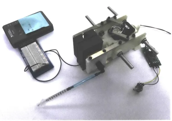
3-6 Experim ental setup . . . . 25
PFRIM I I 1 11 'M I wpm - -l RIPM--, -- ll---'." , - -- Illl 11- wjmmwAmmNmwmmmm"FwmlRRl
List of Tables
3.1 Rubber molding ratios . . . .
4.1 Comparison of Shapes . .. . . . . 20
Chapter 1
Introduction
Many prosthetic devices for upper limbs have been developed in recent years. One feature lacking from many of these, however, is the ability to provide sensory feedback to the user about gripping force.
There are a variety of paths that other prosthetic devices have explored in at-tempting to provide sensory feedback. Some of these target nerves and require in-vasive procedures to attach to the user's nervous system, while others use electrical stimulation to the skin [1]. Few have attempted to provide sensory feedback through force transmission, which allows for a non-invasive device and a method of feedback that mimics the physical action of gripping an object [2]. In the same manner that a human's skin depresses slightly when touching an object, this experiment tests how various rubber-molded robotic fingertips respond to gripping force.
Chapter two describes the current design of the device, as well as the main con-straints on miniaturizing it into a wearable version.
Chapter three describes how the experiment was designed, set up, and run. Chapter four discusses the results of the experiment.
Chapter five discusses the conclusions and future expansions of this work to lead to a fully wearable version of the device.
Chapter 2
Background
2.1
Current Design
The current design of the device was created by Erich Meinig, and involves two robotic fingers actuated by one motor and connected to a hydraulic system and user armrest. The fingertips are made of rubber and filled with fluid, so that they compress and displace a certain fluid volume when gripping. This fluid displacement is carried through a hydraulic system that terminates in two syringes, whose plungers are forced upwards to press into the users arm, allowing them to feel sensory feedback on how much force the object is being gripped with.
The fingertips are hollow hemispheres molded out of Vytaflex 40 rubber, with a thickness of 1.5mm, radius of 18mm, and interior volume of 12.215 x 103 mm3. The
robotic fingers are actuated by a Dynamixel MX-106 motor, which provides max torque of 8.4Nm at 12V. A SyRen 25 motor driver connected to a potentiometer is used to manually control the motor.
2.1.1
Pascal's Principle and Pressure Sensitivity
This system operates on Pascals Principle, meaning that in a hydraulic system with a confined fluid, a pressure change at one end will result in the same pressure change at
of force, the pressure increase causes the rubber finigertips to deform and displace a certain volume of fluid, which then causes a pressure increase at the syringe end of the device. Since Pressure is Force divided by Area, and the fingertip contact area is larger than the syringe contact area, a smaller force at the grippers will result in a larger force on the user's arm.
P1 = P2
F11A1 = F2/A2
With the goal of providing sensory feedback, the first constraint on the devices de-sign is the minimum pressure that can be felt by humans. From prior experimentation
by Erich Meinig, the minimum pressure that can be felt on the human arm is 4kPa.
In this device setup, the contact area of the plungers on the skin is approximately 45mm2
To relate force to volume displacement, we can use Archimedes' Principle for buoyant water force:
Fuoney= pwaterVw,dispg
Substituting this into Pascal's Principle, with Pwater = 1g/mL and g = 9.8m/s2
we can determine the volume displacement required for a given gripper force F1:
P1 = P2 F1 = P2A1 =F 1 Vis, = ----pwg
2.2
Project Goal
The primary goal of this project is to obtain design guidelines for optimizing the size and performance of the robotic fingertip grippers. With a sense of how various
grippers respond to gripping force, they can then be optimized for the desired size and performance.
Chapter 3
Experimental Design
3.1
Gripper Designs
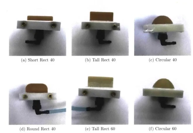
In order to characterize specific attributes of the designs, such as shape or material, six different fingertip molds were tested in total. First, a rectangular design with the same interior volume and mold material as the current hemispherical design was created, in order to isolate the effect of a different gripper shape. Then from this design, the material and height were varied. After this, a rectangular gripper modified with rounded corners and the same height was tested to investigate the effect of corner
stiffness.
3.2
Manufacturing Process
3.2.1
Casting and Molding
To create the rubber fingertips, molds first had to be designed and 3D printed. These molds were then filled with either Smooth-On Vytaflex 40 or Vytaflex 60 liquid ure-thane rubber mixture. The casting process is as follows:
1. Open the molds and spray the insides with mold release. Once they have been
qp
4
(a) Short Rect 40 (b) Tall Rect 40 (c) Circular 40
(d) Round Rect 40 (e) Tall Rect 60 (f) Circular 60
Figure 3-1: Various gripper designs. The short rectangular gripper has a height of 9mm, while all the others have a height of 18mm. The tall rectangular grippers
were designed to have the same interior volume as the circular ones.
Material Vytaflex 40 Vytaflex 60 Smooth-Cast 305 Part A 12g 12g 5.3g Part B 12g 12g 4.7g
iii
Table 3.1: Rubber molding ratios. Each mixture requires a part A and part B to be poured out and mixed to start curing. The Vytaflex are urethane rubbers, while Smooth-Cast is a resin used in this experiment to seal the Vytaflex onto the device's Delrin fingertip base plates.
20 Total 24g 24g log I
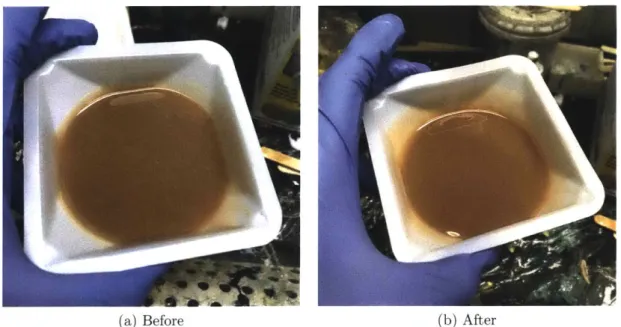
(a) Before (b) After
Figure 3-2: Removing air bubbles with vacuum chamber.
3. Place mixture in vacuum chamber to remove the air bubbles. It takes
approx-imately two to three minutes at 30 PSI. Once the bubbles start to form, they are clearly visible and rise up from the surface of the mixture. When they have mostly disappeared, slowly depressurize the chamber and remove the mixture. It should appear glossy and smooth, with no visible air bubbles inside.
4. Fill a 10mL syringe with the mixture. To ensure there are no air bubbles when filling the mold, which would create holes in the cured rubber, turn the syringe upside down, wait a few seconds for the air bubble inside to rise, then depress the syringe slightly until the air bubble is released. Insert the syringe tip into the matching hole on the mold, and fill until the mixture reaches the gaps in the top. Remove the syringe and fill the rest of the hole until it is even with the top surface.
5. Let the mold cure for sixteen hours at room temperature, or five hours in an
furnace at 70 degrees Celsius.
I -.
Figure 3-3: Section view of the two-part tall rectangular mold. The 10mL syringe inserts into the center hole and dispenses the liquid rubber mixture down, where it then fills the mold channel.
3.2.2
Machining the Fingertip Base Plates
The base plates that the molded tips are sealed onto were machined out of 10mm thick Delrin. From prior experimentation done by Erich Meinig, 3D printed base plates resulted in leakage when the grippers were depressed. Using Delrin prevented this issue, although it requires the extra step of machining.
All of the fingertip designs tested in this project used the same base plate. Using a
1/4" end mill, a rectangular slot was milled to a depth of 2mm. A center through-hole of diameter 7/16" was then drilled and tapped for the requisite valve. See drawings in Appendix B for precise dimensions of the base plates.
Figure 3-4: Fingertip base plate machined out of 10mm thick Delrin.
3.2.3
Sealing and Finishing
Once the rubber grippers are molded and the base plates are machined, they must be attached. The rubber gripper should fit snugly when placed to sit flat in the rectangular slot. Pour and mix the proper ratios of Smooth-Cast 305 resin until the mixture is homogenous. Then simply pour the mixture over the gaps between the rubber and base plate slots. Excess can be poured over the rest of the Delrin surface to ensure a tight seal. Let the Smooth-On cure for thirty minutes.
Once the part is cured, heat-set threaded inserts for M4 must be placed into the holes on the sides of the base plates. When these are finished and cooled, the entire gripper is ready.
3.3
Setup and Testing
3.3.1
Fluid Setup
Attach the valve and tubing to the gripper. Squeezing the gripper flat, submerge the entire gripper in a bucket of water and release the rubber to allow water to fill the chamber. Keeping the tube opening underwater, take a 10mL syringe and fill with a few milliliters of water. Attach the syringe to the tubing and pull the plunger up to remove as many air bubbles as possible from the gripper chamber. Once the plunger can go no further, push the plunger down to re-fill the chamber with fluid, then release the plunger and let it come to rest. Remove the plunger and replace with a 1mL syringe.
3.3.2
Motor and Load Cell Setup
To drive the Dynamixel MX-106 motor, a potentiometer was connected to the control board, allowing the motor to spin in both directions to open and close the gripper.
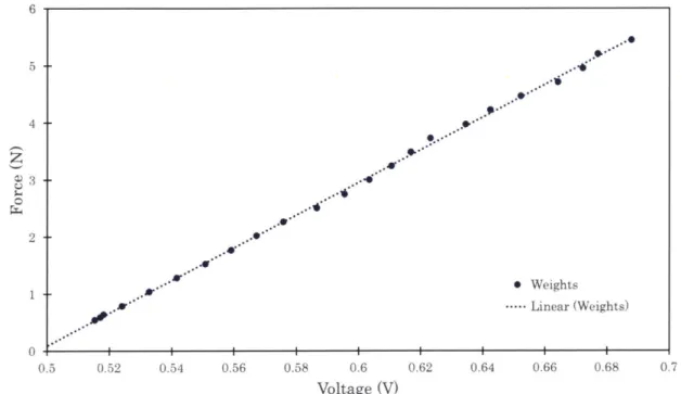
To collect data, a TE Connectivity FC22 load cell was connected to a NI MyRIO and set up in LabView. A 3D-printed enclosure held the load cell in place and
provides voltage readings, and to convert these to force readings, brass weights of known masses ranging from 5g to 500g were placed on the load cell and measured. Using F = mg, with g = 9.8m/s2, the masses were converted from grams to Newtons.
The linear relationship calculated from these measurements was then used to convert the rest of the experiment data from voltage to force.
6 ... 0 e..--. 5 4 ... 0. - Weights .. . . . .----.Linear (Weights) 0 I I I I I I I I 0.5 0.52 0.54 0.56 0.58 0.6 0.62 0.64 0.66 0.68 0.7 Voltage (V)
Figure 3-5: Known masses of weights were placed on the load cell to obtain a conver-sion equation from the readout units of volts to the desired analysis units of Newtons. The linear fit equation is F = 28.604V - 14.208.
3.3.3
Running the Experiment
Each gripper was tested one at a time due to inconsistency in contact area when both grippers were attached simultaneously. The fingertip gripper was pressed flat onto the load cell surface until specific volume displacements were reached. Voltage readings were recorded at intervals of 0.1mL displacements from OmL to 1mL. Three trials were run for each gripper.
26
Chapter 4
Results
Comparing the six different grippers, several categories of analysis can be distin-guished. First, the slopes show how quickly the force required to compress the gripper increases for larger displacements of fluid. Second, the y-intercepts show the mini-mum amount of force needed to begin actuating the grippers at all. For a human to feel any sensory feedback from this device, a minimum of 0.2mL must be displaced.
The slope is essentially a guideline for sensitivity when driving the motor. A larger slope requires greater variation in gripping force. With a motor controlled by a potentiometer, this allows more error for the user when physically turning the poten-tiometer. An accidentally slip of turning the potentiometer too far, and increasing the motor grip force more than intended, would result in a smaller unintentional volume displacement than a gripper with more sensitivity and less room for error.
4.1
Comparison of Shapes
4.1.1
Circular vs. Rectangular
From comparison of the Vytaflex 40 grippers, "Circular 40", "Tall Rectangular 40", "Short Rectangular 40", and "Rounded Rectangular 40", certain characteristics can be noted. The circular gripper requires the least amount of force to compress, which
60 50 ...- .--- .Short Rect 40 ... Tall Rect 40 40 - Round Rect 40 Circular 40 . Tall Rect 60 0 m - . --e -Circular 60
* --.... --Linear (Short Rect 40)
2 0-- -- - --.- . . - L i n e a r ( T a l l R et 4 0 )
Linear (Round Rect 40) ....-- Linear (Circular 40)
10.... - . .. ... -Linear (Tall Rect 60)
- .-.- .... ... -.- .-- Linear (Circular 60)
0 I I I I I I I I I
0 0.1 0.2 0.3 0.4 0.5 0.6 0.7 0.8 0.9 1
Volume Displaced (mL)
Figure 4-1: The amount of force required for specific volume displacements. At least 0.2mL of displacement is necessary for the pressure change to be felt by the user at the other end of the device.
Shape Slopes (N/mL) Y-Intercepts (N)
Tall Rect 40 0.27 20.43
Round Rect 40 0.58 11.048
Circular 40 0.93 4.41
Short Rect 40 2.57 0.73
Table 4.1: Comparison of Vytaflex 40 gripper shapes. The short rectangular shape has by far the largest slope, so it is least sensitive to changes in gripping force.
grippers. Surprisingly, the short rectangular gripper has the largest slope of all. At the larger end of volume displacements, this can be explained by the gripper nearly flattening out as it runs out of internal fluid to displace.
4.1.2 Height of Rectangular Grippers
The tall rectangular grippers have similar slopes, while the short rectangular gripper has a visibly steeper slope. Of all the grippers, the short rectangular gripper requires the least amount of force to begin displacing volume from 0 to 0.2mL, although after that it quickly rises. It also has the largest slope of all, meaning that it is the least
sensitive to changes in gripping force.
28
4.1.3
Rounded Corners on Rectangular Grippers
The rounded rectangular gripper mitigated the stiffness of the original rectangular gripper's corners, requiring about half the gripping force as the tall rectangular gripper made from the same Vytaflex 40 material. Of all the rectangular grippers, it is the most similar to the circular ones.
4.2
Comparison of Materials
The difference between Vytaflex 40 and Vytaflex 60 is starkly clear in the tall rect-angular grippers, with nearly double the amount of force required to compress the Vytaflex 60 for the same shape and volume. For the circular grippers, the difference is less obvious. They have similar slopes, but the circular 60 gripper requires slightly more force to compress, with a 6.ON required to begin compression as opposed to the circular 40's requirement of 4.4N.
30
Chapter 5
Conclusions and Future Work
Characterizing these different grippers helps inform future design decisions in opti-mizing the device for size and wearability. The circular Vytaflex 40 gripper requires the least amount of force to actuate, but some of the rectangular grippers are actually quite similar in performance. In particular, the rounded rectangular gripper has a similar slope, but needs approximately double the force as the circular one.
With a powerful motor such as the Dynamixel MX-106, however, the additional required force does not preclude using the rounded rectangular gripper. Other than the tall rectangular Vytaflex 60, which requires at least 20N more force than any of the other grippers, any gripper can be chosen since the Dynamixel can easily provide enough torque to displace at least lmL of fluid in any of these.
Being able to choose rectangular grippers, as opposed to circular ones, provides several advantages. First, the shape is narrower, and more closely mimics the shape of a human finger. This allows the width of the prosthetic device to be reduced, and more robotic fingers could be added as well. With the reduced width of the rectangular grippers, a smaller motor can also be chosen to reduce the overall width of the device. Second, the surface contact area of the rectangular grippers is larger than the tip of the circular ones. This allows for more friction and less slippage when
picking up objects.
the user. As such, the Vytaflex 40 material is preferable to the Vytaflex 60 because it can be more easily deformed. Additionally, using either the circular or short rect-angular grippers allow for the smallest activation force, particularly at low volume displacements (up to 0.4mL). After 0.4mL, the rounded rectangular gripper is the rectangular gripper that requires the least force.
In future work, other optimizations must be made to make this device fully wear-able. By understanding the characterization of the different grippers, future designs can be modified and a gripper chosen based on use case requirements.
Bibliography
[1] C. Antfolk, M. DAlonzo, B. Rosen, G. Lundborg, F. Sebelius, and C. Cipriani.
Sensory feedback in upper limb prosthetics. Expert Review of Medical Devices, 10(1):45-54, 2013. PMID: 23278223.
[2] F. Cordella, A. L. Ciancio, R. Sacchetti, A. Davalli, A. G. Cutti, E. Guglielmelli, and L. Zollo. Literature review on needs of upper limb prosthesis users. Frontiers