Publisher’s version / Version de l'éditeur:
Vous avez des questions? Nous pouvons vous aider. Pour communiquer directement avec un auteur, consultez la première page de la revue dans laquelle son article a été publié afin de trouver ses coordonnées. Si vous n’arrivez pas à les repérer, communiquez avec nous à [email protected].
Questions? Contact the NRC Publications Archive team at
[email protected]. If you wish to email the authors directly, please see the first page of the publication for their contact information.
https://publications-cnrc.canada.ca/fra/droits
L’accès à ce site Web et l’utilisation de son contenu sont assujettis aux conditions présentées dans le site
LISEZ CES CONDITIONS ATTENTIVEMENT AVANT D’UTILISER CE SITE WEB.
Proceedings of the 9th International Conference on Offshore Mechanics and
Arctic Engineering (OMAE '90), 4, pp. 283-288, 1990
READ THESE TERMS AND CONDITIONS CAREFULLY BEFORE USING THIS WEBSITE. https://nrc-publications.canada.ca/eng/copyright
NRC Publications Archive Record / Notice des Archives des publications du CNRC :
https://nrc-publications.canada.ca/eng/view/object/?id=1e8ab5d5-e51c-4e58-952c-d398de0b4c5b
https://publications-cnrc.canada.ca/fra/voir/objet/?id=1e8ab5d5-e51c-4e58-952c-d398de0b4c5b
NRC Publications Archive
Archives des publications du CNRC
This publication could be one of several versions: author’s original, accepted manuscript or the publisher’s version. / La version de cette publication peut être l’une des suivantes : la version prépublication de l’auteur, la version acceptée du manuscrit ou la version de l’éditeur.
Access and use of this website and the material on it are subject to the Terms and Conditions set forth at
Is minimum creep rate a fundamental material property?
Ser
T H I
A , " .9
9
0
National Research
Conseil national
L D G .
*I
Council Canada
de recherches Canada
-
- -
Institute for
lnstitut de
Research in
recherche en
Construction
construction
Is Minimum Creep Rate a Fundamental
Material Property?
Reprinted by
The American Society of Mechanical Engineers
Book
#
10296F, 1990
pp. 283-288
(IRC Paper No. 1704)
NRCC 32374
N R C-
CISTII
I R C
L I B R A R Y
./Ill 15
!!I91
B I B L I O T H $ Q U E
I R C
C N R C-
IClSTI
-
Les probl&mes de genie des glaces exigent des solutions pour ce qui est des limites
particulikres de contrainte, de ddforrnation ou d'endomrnagement. Les ingCnieurs doivent
connaim l'interdependance des contraintes, de la dkformation, du de& d'endomrnagement
et du temps, dans le cas d'une masse de glace, pour m e distribution des tempkratures et
une
histoire de chargement donnCes. I1 est d'usage courant, lorsqu'il s'agit de dkterminer
les propri6tCs mCcaniques de la glace, d'kvaluer l'influence de la vitesse sur la contrainte
maximale ou Ia dkpendance de la icvitesse minirnale de fluagew l'kgard de la contrainte.
Cette
vitesse minimale de fluage (on parle aussi de fluage usecondairem ou uen rCgime
permarnena) e
t les lois de vitesse, exposants de contrainte et coefficients correspondants
ont une valeur limitke en ce qui concerne les conditions effectives de s e ~ c e .
Ils ne sont pas
v&s utiles non
plus pour consmire des Quations constitutives permettant d'analyser des
problkmes complexes de gknie des glaces. L'ingenieur doit plutat se concentrer sur les
phCnom&nes transitoires liCs
?la structure et
iB
la texture, sur la cinbtique des dommages
causCs
par
Ies fissures et sur les effets attaches, dans le tout premier pour-cent de
ddfomtion
par fluage.
The American Society
of
Mechanical Engineers
Reprinted From
Proceedings of The Ninth International Conference of Offshore Mechanics and Arctic Engineering Editors: 0. A. Ayorinde, N. K. Sinha, and D. S. Sodhi Book No. 10296F
-
1990IS MINIMUM CREEP RATE A FUNDAMENTAL
MATERIAL PROPERTY?
N. K. Sinha
National Research Council of Canada Ottawa, Ontario, Canada
Abstract
lee engineering problems requlre solutions In terms of speclflc design stress, strain or damage [imlts. Engineers must know the interdependence between stress, strain, damage state and time for a given
ice
body at a given temperature distribution and IoadIng history. Common practice of determining the mechanbal properties of ice Is to evaluate the rate sensitivity of maximum stress or the stress dependence of minlmum creep rate. 'Mlnlmum creep rate' (also known as 'Secondary' or 'steady-state') and the corresponding rate laws, stress exponents, and coefficients are of Ilmlted value wlth respect to actual serviceI conditions. Neither are they of much use in building constitutive I equations for analyses of complex ice engineering problems. The engineer must focus instead on the structure and texture-sensitive transient phenomena, kinetics of crack damage and the associated effects within the very first percent of creep deformation.
I
IntroductionCreep and fracture of polycrystalllne
Ice
is part of a larger fleld of study-
deformation and failure of materials at high homologous temperatures. At temperatures greater than 0.3 T,, where T,,, is the meltfng point in Kelvin, total straln, E, can be described phenomsnologlcally in terms of elastic strain, e,,delayed elastlc straln, E,, and permanent or vlscous strain,
q,
An engineering structure or component can be designed to function properly and to achieve the required life under speclfled operating conditions wlthout falure If the creep, creep damage and fracture charackerlstics of a material are known and Eqn. 1 is formulated for
any
loading history taking account of the physical processes involved. To date most treatments for engineerfng design,lnctuding
Ice
engineering, are ernphicalin
nature and based on oversimplified rdeas. These ideas have been challenged recently. Examination of the physical phenomena governing creep deformation and
the
klnetlcs of creep damage has given new directions that are discussed in this paper.Constitutive Eauatlons
Most theoretical treatments, for simplicity, are based on the notion of a steady-state matrix creep rate, is,, and an idealized form of Eqn. 1,
Since steady state creep rate, b
.,
is synonymous with 'minimum creep rate',&,
Eqn. 2 is re4aced by,E = E e + E d + & t (3)
where
.&,,
= Ao"
(4)where A and n are constants,
o
is stress. Eqn. 4, known as Norton's law or simply the power law, was used by Glen (1955) for ice. Since it breaks down at high stresses, Barnes et al. (1971) adopted the unifying Garofalo (1965-proposed for metals) equation, where b is another constant,&,,
= A [sinh (bo)In
Following the ideas of Garofalo (1965) and others that there must be interrelationships between primary and secondary creep in metals, Ashby and Duval (1985) introduced the following expression in ice mechanics,
and proposed a 'modified Sinha equation' in terms of ' Eqn. 6 is based on the popular Monkman and Grant (I&& type expression, where t, is the time to reach
&,,,
kintrn = constant
One of the consequences of the governing Eqn. 4 or 5 and the underlying concept of steady-state is the development of the idea that a 'maximum stress', om, should be obtained if a constant strain rate, 6, is applied,
Polvcrvstalline Ice
Any body containing several crystals is a polycrystalline
body. The crystals
are
commonly referred to as grains and canhave substructures. Polycrystalline ice, including sea ice, can be grouped essentially Into three major types:
-
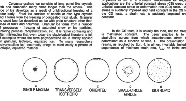
granular, columnar and frazil. A brief description follows on the type of polycrystalline ice encountered in nature and the tests performed to determine mechanical properties.Columnar-grained ice consists of long pencil-like crystals with one dimension many times longer than the others. This type of Ice develops as a result of unidirectional freezing of a water body. Frazil Ice conslsts of needle or disc type crystals and it forms from the freezing of congealed frazil slush. Granular ice could best be described as Ice with grain structure other than those of frazil and columnar. Granular ice forms from a number of processes
-
freezing of saturated snow or ice particles, slntering process, recrystallization, etc. It Is rather confusing and often misleading that even today the glaclologlcal literature is full of examples where the term polycrystalline ice Is sbictly applied for granular, Isotropic, equlaxed Ice. To many researcheffi 'p~lycrystalline ice' incorrectly brings to mlnd solely a picture ofIsotropic, equlaxed material.
As for granular Ice, the situation is rather complicated.
It has been shown that the 'easy' glide crystal orientation of granular ice in compression is a fabric with a small drcle girdle (Gao and Jacka, 1987; Jacka and Budd, 1989) as shown inFig.
Id.Mechanical Tests
Two commonly appled experiments to determine material propertles of ice at a constant temperature for engineering applications are the unlaxlal constant stress (CS) creep and the uniaxlal constant strain or deformation rate (CD) tests. Ideally a stress Is suddenly imposed and held constant in the CS tests; in the CD tests, a strain rate Is suddenly Imposed and held constant.
In the CS tests, it is usually the load, not the stress, that
Is
maintained constant The usual practice is to record straln/time curves from whlch Instantaneous strain rate is determlned as a function of time, t. The presentation of test results, as required by Eqn. 4, is almost invariably limited to the dependence of minimum strainrate,
&,
on inltial stress, o.a
b
c
d
e
SINGLE MAXIMA
TRANSVERSELY
ORIENTED
SMALL-CIRCLE
ISOTROPIC
ISOTROPIC
GIRDLE
Fig. 1 Some commonly obsewed crystal orientation fabrics of ice. Ice Fabric
-
Shaoes and Anan~ements of CrystahPhysical propertles of b depend on the
structure,
texture,fabric, lmpurttles and inclusions of the Ice (see Members, 1980
for definitions), and the nature of the stress state with respect to the crystal structure. A few common crystal orlentatlon fabrics, excluding the multiple maxima, are shown In Fig.1
The
crystals
In one of themwt
commontype
ofW,
S1type columnargrained (Michel and Ramseier, 197f),
are
oriented to have thetr opHc or c-axis tending to be pmflel to the length of the columns-
parallel to the verb'caI plane in an ice cover. Thls ice, therefore, has a fabric wlth a single maximum (Flg.la).
Maxlrnum resistance to flow in thts Ice develops if a load is applied parallel to the long axls of the grains orea~ls.
Thls loadlng configuration Is equivalent to a 'hard' glide. Because the basal planes of the grdns colneEde with the plane of the icecover, a
uniaxlal
load apphcation In a plane at about 45" to fhe axis of the grains Is equlvarent to an 'easy' glide, 1.0. the rnaxfrnum shearstress
being parallel to the basal plane. Slmllarly, 'easy' gllde corresponds to a load application in a planeat about 45" to the long axis of the gram for transversely Isotropic, columnar-grained, S2 type ice (Fig. Ib) because the
basal planes of the grains In fils ice tend to be parallel to the length of the grains.
' H W
or 'easy' glue modes of Icmdlng can ocwr, relatively speaking, in the samewane
(horizontal) In oriented S-3 type landfast, columnar-grained sea ka (Fig. IC) In whlch the caxis of
the
gralns is In the horizontal plane but tending to be parallel to the water current below theIce
cover.lnformation is usually not provided on the magnitude of axial strain, lateral strain and volumetric strain, or any interdependence between strain components, strain rate and time, and their dependence on stress, grain size, structure, texture, etc.
In CD tests, it is usually the displacement rate of the cross-head or the actuator (excepting a few recent tests using closed-loop systems), not the specimen strain rate, that Is malntained constant.
As
requlred by Eqn. 8, maxlmum stresses are reported In terms of nomlnal strain rates estimated from the cross-headrate
and specimen length. Vital lnformation on stiffness characteristics of test systems and histories of stress, specimen strain, cracking activities, etc., are usually not measured, reported or discussed.Problems
A large number of CS studies have been canled out on granular ice. Most of these studies are difficult to understand and analyze because the minimum creep rates were reported without providing a comprehensive picture of the creep-time data. Tests were often conducted over a wide range of stresses and temperatures involving stress- and temperaturedependent complex kinetics of microfracturing and cavitation. Moreover microstructural studies were rarely carried out after the tests.
The tests could, however, be divided into two major groups based primarily on whether any microcracking activities are involved during deformation. Since high temperature embrittlement processes play dominant roles at uniaxial stresses
above about 5 x
lo.",
where E is the Young's modulus, tests at stresses below about 0.5 M N . ~ " could be considered as low stresses for ice.Minimum Creer, Rate at Low Stresses
The cuncepta of &ady state and Eqn. 2
are
Ideallzatfons.The ttansformatfon
of
Eqn. 2 to Eqn. 3, Is a result of practicalnecessity for describlq the pm-ternary creep reglme. Usual forms of Eqn. 3 do, however, glve the impression that creep rate
Is 'believed' to decrease with time approaching a prolonged, quasi steady-state, 'secondmycreep' reglme, assdated with a 'minimum creep rate'.
Recent experimental observations at the University of Melbourne have given an understanding of the creep response of granular ice for low stresses relevant to the deformation of land-based natural ice masses. Initially isotropic ice (Fig. le) shows a monotonid$ dyreasing strain rate until a minimum creep rate of 1.2 x 10 s- Is reached at an octahedral strain of about 0.6% (at-3.3% and 0.2 MN.rnq*), and then the strain
rate
Increases agaln to a quasi-constant strain rate at a strain of about 10% (Jacka and Budd, 1989). However,
an
Initially anlsdroplc Ice, axhibltlng a srndl clrclecrystal
orientation fabric (Fig. Id), exhlblts a rnonotonlcally decreasing straln rate during loading leadlng to a minlmum octahedral creep rate of 3.5 x 1QS-I at octahedral straln of about 10%. Both types of ice exhibit slmllar final crystal fabric patterns with a small circia girdle. Mlnlrnum creep rate lor IsotropFc lee,
therefore,
isol
transitory naturo and does
not
slgnlfy a steady stnts. These and other observations led Jacka and Budd (1989) to conclude that the concept of a steady state secondary creep condltlon islnvalld for initially lsotroplc Ice because of the development d
crystal anisotropy durlng deformation. It seems that the tertiary flow rates for anisotropic Ice are more appropriate for Ice sheet flow than the minimum strain rate is for isotroplc ice (Jacka and I Budd, 1989).
UNLOADED
%
[
g
4
i
TIME. 10 s
I
' d = 4.4 mm
(TESTL141M) GRAIN DIAMRER. d
-
1.5 mmEQUIPXED ICE
a -3.16 x l ~ l - ~ E ( 3 M N m-9 0.96 T," ( M K )
0 1 2 3 4 5
TIME. 10 9
Fig. 2 Observed grain size effect on creep in Isotropic ice.
Minimum C r e e ~ Rate at High Stresses
A significant number of CS studies have been carried out on mechanical properties of ice for stresses, greater than about 0.5 M~.rn-~, relevant to many engineerlng applications (for example, Glen, 1955; Barnes et al., 1972; Gold, 1965; Mellor and Cole, 1982; Sinha, 1989ac). M@anical response of polycrystalline ice In this range is affected by grain-facet size microcracking activities (Cole, 1986, Sinha, 1989b). There Is, however, a tendency towards reporting only rudimentary detalls on the mlcrostructural characterlzatlon. Such llmlted detall Is essentially useless.
TIME, s. 10'
Fig. 3 Observed grain size effect on creep in tansversely isotropic columnargrained ice.
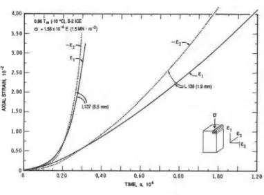
For isotropic, equiaxed, granular ice, the total strain shows a decelerating or primary creep stage followed by a secondary quasi steady state and an accelerating or tertiary stage as can be seen in Fig. 2. A similar response has also been observed for transversely isotropic columnargrained S2 ice (Fig. 3) loaded perpendicular to the columns. Microfracturing activities during deformation have been shown to affect axlal deformation and volumetric strain (dilatation) in the material. Both granular ice (Fig. 4) and columnargralned ice (FQ. 5) exhibit microfracturing and volumetric dilatation during deformation. The entlre creep curve
of
both granular and columnargralned Ice shows slgnlflcant dependence on graln slze (Slnha, 198Ba,b). Primary as well as tertiary creep rate are strongly Influenced by grain size (Figs. 2,3). A knowledgeof &,,
provldes neither the creep rate nor the creep straln during the prlmary creep period or thetertlary
range.Columnar-grained ice, similar to 5-2 type but with a slight anisotropy fabric (tending to be small circle girdle) in the plane normal to the length of the columns has been found to exhibit an accelerating primary weep period before going into decelerating creep (Sinha, unpublished). Initially increasing creep rate
response in columnar-grained ice has also been observed by Gold (1965) at stresses in the range 0.4 to 1.3 M N . ~ - ~ and strains up to 1 x
lo-'.
The same specimens were, however, reported to exhibit lower creep resistance and 'normal' initial decreasing creep rate response on reloading of the damaged specimens. These observations also give clear indications that it would be difficult to formulate the overall creep response on the basls of any steady state.creep concept.I
The d u d o n of
the
secondary weep regime decreaseswlth
Increase in stress for stresses greater than 0.5 MN mQ In uniaxlal tests (Figs. 4, 5). Thesecondary
creep regime disappears with increase in stress and only a transitory minimum creep period followed by an accelerating tertlary creep regime Isnoticed at
stresses
of engineerlng interest as can be seen In Figs. 2 and 3. The 'mlnlmum creep sate' slgnlfles only apolnt on the creep curve and Eqhs. 4 or 5 applles only to
thts polnt. The basic assumption of stable microstructure, ideally associated wlth the concept of steady state, is not valid for minimum creep reglme at stresses of engineering importance. Moreover, experimental results showing significant grain-size effects ralse questions to the valldity of Eqn. 6. Since the usual Eqns. 4 or 5 for
&,,
do not showany
dependence on grdn slze and shape or the ice type, the question raised Is: How useful is Eqn, 6 for real life Ice problems?. Therefore, constitutive equatlons expressed in terms of L,,,such
as Eqn. 6 are of little practical or physical value. In general it would be fair to saythat:
creep is a continuous process and each regime depends on earlier creep history;
use of the term 'minimum creep rate' synonymously for 'Steady-state creep rate' is a 'misuse' of language; 'minlmum creep rate' does not always imply steady state condition.
?
+
UNLOADED 263 K. ISOTROPIC ICE, GRAIN DIAMETER
.
1.6 mmz
Fig. 4 Experimental Dbsemtlons on axlal straln and volurnetttc straln under constant mrnpresslvs load for lsotroplc Ice.
The conoept that
the
rnlnirnum creep rate b abask
quantityIn engineering applications in man-made materials such as
metals, alloys and mramtcs has, however, found Its
way
lnto Icemechanics. Analyses of innumerable problems (ice englnaerlng no exception) have been carried out on the basis of ignoring the fact that It mually occurs only 'momentarily durlng a
creep
test. Consequently, most experimental observations In polycrystalline metals, alloys, cerarnlcs and Ice have beenconducted sxcluslvely to find the stress and temperature dependence of
h,
using uniaxial constant bad tests. Mosttheories in metals. alloys and ceramim have also been developed to satisfy stress and temperature dependence of
'I"'
Aconsequence of these practices Is the profusion o elther ernplrically developed or theoretically formulated mathematical eouations to describe constant stress ICS) creep, as well as
constant strain rate (CD) deformation' experiments. These equations, inadvertently but lnevltably have led to confusion.
ONE GAUGE
FEU OFF
-
-
-
24 2.1 263 K, TRANSVERSELY ISOTROPIC ,S-2 ICE, GRAIN DIA = 2 mm
3.0
I I I t 1 I l l
Fig. 5 Experimental observations on axial strain and volumetric strain under constant compressive load for transversely isotropic ice.
Constant Deformation Rate Test
Hlstodcally, It is the cross-head or the actuator dlsplacernent rate that Is malntalned constant fn CD tests so that the experiments are conducted at constant: 'nominal' strain rates,
i
=ill,
where xis
the cross-head displacementrate
andL,
is t e spedrnen gauge length. This tradition is so strong that often no distinction Is madebetween
specimen strain rate and k,, or todraw attention that the tests are Indeed
not
constant sttarn rate tests. In a CD test, the total displacement after a loading time, t, Is given by the sum of the specimen displacement, x,, and the machinelsystem displacement, x,,k = (x,
+
xm)lt (9)If i- (= x$(Lt)) is the average specimen strain rate to time, t, then Eqn. 9 gives the nominal strain rate as,
If E is the spring constant of the test machinelsystem, A. is the initia cross-sectional area of the specimen and P is the total load, then x, = PIE, and P = a A. where a is the engineering stress. Eqn. 10 then gives,
According to Eqn. 11 the average specimen strain rate to t depends on the geometry of the specimen, stiffness of the Zest system and the time of loading. For a g b n test system
and specimen geometry, k- approaches
e,,
as t increases and equals at t =-,
which, however, corresponds to infinlte strain. Such a responsfi has been observedIn
ice at strain rates less than 5 x 10"s-
.
A quasi-steady state deformation rate and a constantvalue
of stress have been obsetved along
timeafter
the beginning of loading, satisfying, therefore, the underlying concept for transposing Eqn. 4 to 8. These slow CD tests areslrnllar to
CS
tests at stresses less than a b u t 0 5 MN.ma, for whlch a quasl steady-state is reached eventually during loading, justlfylng the assumed equallty between the ldealizatlon (Eqn. 2) and its practical reality (Eqn. 3). The long-term response of the slow CD tests is equivalent to the long-term part oflow
stress CS tests.It should be mentioned here tftat a closed-loop test
system, with the controlling dfsplacement game mounted dlrectly on the specimen, is equivalent to a machlne with very hlgh stlffness and gives
&
= i, instantaneously. At low straln-ratesthe Stress asyrnptoffcally approaches a rnaxlmum value. Nevertheless, the long term response provides neither any basis
of analysis for the system response or any information on the shape of the stress-shah diagram.
For sfraln rates higher
than
5x
lo4
8-', of englneerlnginterest, a finib time,
,
.
-
t
andh e m
a flnlte straln, q,.y is requlred to reach the rnaxlmurn stress,am.
The maxrnum stress actually occurs only 'momentarily' dur~ng a CD tests onIce.
A power-law has Indeed been found to apply for upper-yieldtype of failures. This has strengthened the notions of steady-
state creep and "uctlle Failure', In spite of obsenred severe cracklng activities. Consquently, premature fractures, that did
not follow the expected power-taw, were termed 'Blittie', leading to the concept of 'Ductile-to-Bfittle' transltfon.
A review of experimental results on 5-2 Ice (Slnha. 1981) shows the value of m (3 to 4), in Eqn. 8, nearly equal to
n
(about 3), In Eqn. 4, but the value of M varies signiffcantly (1.8 x $0''
to
1.5 xlo6
at -lO°C) witf~ the stiffness of the testsystem.
M (Eqn. 8) was shown to decrease with an increase in
system
stlffness and to approach the nurnerlcal value of A(Eqn.
4) as the stlffness approaches Infinity. The results obtahed with a conventional machine of flnits sffffness were afso found to agree well with those of a closed-loop machine if average straln rate to upper-yield stress. =+-dh,.
is USECI for analysis. Premature faihres were80und to epend on specimenend
f~nlsh and to occur at lower straln ratesas
the system stlffness increased.Why is M not always equal to A? Why does it depend on external boundary conditions? Why does the ductile-to-brittle transition depend on system stiffness? Why do both failure time,
and failure strain, E
.
decrease with increase in stiffness oft e system? What is%e mechanism of ductile compressive failure? Why are ductile failure strains often less than 1 x
lv3,
similar to those of brittle failures when very stiff machines are used? Why does B provide a better description of the rate sensitivity of upper-ymstress than i,,? Why do the stress-strain curves show rate sensitivity? These and many other questions cannot be answered using conventional wisdom.Most studies on ice, with a few exceptions (Sinha, 1981; Mellor and Cole, 1983), have paid attention only to the correspondence between m and n, and discussed the rate sensitivity of 'strength' in terms of 'secondary or steady-state' creep rate. As a consequence, a considerable amount of effort was made in the past in obtaining results to fit Eqn. 8 and answering irrelevant questions of the form
-
what is the strain rate during an ice-structure interaction? What is the failure envelope7 It was Ignored that the occurrence of a maxlmum.c stress In a laboratory test Is only an Index
-
a translentphase that depends on loadlng hlstory and complex lnteractlons between the machlne and the specimen. lnadeauate A~oroach
In spite of a significant amount of informatlon on the so- called strength and deforrnatlon of Ice, methods of analysls of most ice engineering problems are inadequate. Too much emphasis has been placed on empirically developed equations
that give no consideration to the structure and texture of the material or the physical processes occurring during the deformation.
Predictability of micromechanically based equations are based on simple ideas and assumptions of values for material constants. Material constants are often determined from experiments that seem simple. In fact, experimental conditions are often complicated by interactions between the test specimen and the testing system.
Engineering design incorporates some type of safety factor that is usually based on the allowable deformation or damage under actual operational conditions. Many important ice engineering problems are associated with relatively small strain, dynamic load and stress up to the failure value. The long term information does not provide any fundamental basis to analyze the short-term, transient response required for many engineering applications. Behaviour in the short term depends strongly on grain size, structure and texture. Ice in nature is so variable in structure, fabric and texture that a constitutive equation must Include these factors or state variables. The
success of
a creep or fracture model must thereforebe
ludaed not only on Its compatibility wlth the Eqns. 4 to 8, but also on Its ablllty todescribe the entlre creep curve, prlmaw as well as tertiary.
A more refined constitutive equation would be one that incorporates the state of the material and yet maintains the familiar phenomenological form
-
describing instantaneous recovery, time-dependent recovery and permanent deformation.A general form of Eqn. 1 would be one that expresses elastic, delayed elastic, and viscous components as functions of state variables (Slnha, 1989b), so that,
where E, = E,(O ,T,t,V,)
and
where V, represents internal and external variables that could be influenced by o ,T and t. All the terms in Eqn. 12 are structure and texture sensitive; they could vary during deformation with alterations of the microstructure. A detailed discussion on this subject is outside the scope of this paper. The success of the approach can be judged from the fact that the failure processes can be described under a wide range of loading conditions, including CS as well as CD tests (Sinha, 1988; 1989a-c) and ice- structure interactions (Derradji-Aouat et al., 1990; Marcellus et ai., 1990).
Equation 12 merely recognizes that a material at high homologous temperatures, like ice, experiences irreversible microstructural changes once it Is deformed and that a number of interdependent micromechanisms operate simultaneously. These processes make creep and creep failures very complex. Experiments should be designed a) to measure the axial and lateral strains for estimation of volumetric deformations, b) to carry out measurements of the three strain components (E,, E
and
q)
from strain history after sudden unloading, c) to record fabric, and microstructural details, including substructures and inclusions, before and after the tests, d) to record and to report shape change, if any, to insure 'the uniformity of stress or strain field, and e ) to c a r j out measurements to quantify the damage processes during testing using metalloara~hic,-
-
- .
acoustic emissions &d other techniques.Both Mnlmum
creep
rate' (' ), In constant stress tests,2
and maxlrnum stress (om),
h
conaM
displacement rats tests, represent only transitory phases under specltlc condlilons. Engineers, not famlliw with the detalls of material response, have used these quantities as fundamental material properties for thema!ysls
of wide ranging engineering problems wlthout reallzingthat the assumptions are not valid For the condl~ons undar oxamlnatlon. The concept of
'strength'
Implies a specific materialpropew. This low temperature concept does not apply at the
slevated temperatures relevant to
Ice
engineerlng. It hasretarded growth In the understanding of failure p r o c e s w In ice In genera!. Apptlcation af this concept has misleading Implications, drawing attention away from
one
basic fact: translent or primary creep stage, involving mlwofracturlng and damageaocurnulatim,
plays a domlnant and decisive mle Inmany
engineering problems. Constitutive equations should be based
on state variables to take account of the loading history and the effsct of rnlcro- and mawo-structural
changes
during loading,References
Ashby, M.F. and Duval, P. (1985). The Creep of Polycrystalllne Ice, Cold Regions Sci. Tech. Vol. 11, p. 285-300.
Barnes, P., Tabor, D., and Walker, J.C.F. (1971). The friction and creep of polycrystalline Ice. Proc. Royal Soc. London, Ser. A, Vol. 324, NO. 1557, p. 127-155.
Cole, D.M. (1986). Effect of Grain Size on the Internal Fracturing of Polycrystalline Ice. U.S.Arrny Cold Regions Research and Engineering Laboratory, Hanover, N.H., Report No.86-5, 71 Pages.
Derradjl-Aouat, A., Evgin, E.. and Slnha, N.K. (1990). Flnlte Element Calculations of Ice Pressure on Rigid Structures. Proc. 9th. Int. Conf. Offshore Mechanics and Arctic Eng. (OMAEIASME), Houston, Texas, Feb.18-23, 1990.
Gao, X.Q., and Jacka, T.H. (1987). The Approach to Similar Tertiary Creep Rates for Antarctic Core Ice and Laboratory Prepared Ice. J. de Physique, Colloque CI (Supplement to No. 3), VOI. 48, pp. 289-296.
Garofalo, G.(1965). Fundamentals of Creep and Creep-Frachrre In Metals. Macrnillan Company, New York, Chapter 2, p. 10. Glen, J.W. (1955). Tt-3 Creep of Polycrystalllne Ice. Proc. Royal Soc., London, Ser. A, Vol. 228, No. 1175, pp. 519-538.
Jacka, T.H., and Budd. W.F. (1989). The Use of Tertiary creep Rates in Ice at Hiih Strains in Compression and Shear. IUTAMllAHR Symposium on Ice-Structure Interaction, August 14- 17, 1989, St. John's, Newfoundland.
Marcellus, R.W., Sander, M., Sinha, N.K., and Shah, V.K. (1990). A Theoretical Dynamic Ice Structure Interadion Model for Crushing wlth Extraction. Proc. 9th. Int. Conf. Offshore Mechanics and
Arctlc
Eng. (OMAWASME), Houston, Texas, Feb.18-23. 1990.Mellor, M., and Cole, D.M. (1982). Deformation
and
Failure of Ice Under Constant Stress or Constant Strain-Rate. Cold Reglons Science and Technology, Vol. 5, pp. 201-219.Mellor, M., and Cole, D. M. (1983). StreWStraln/Time Relations for Ice under Uniaxial Compression. Cold Regions Science and Technology, Vol. 6, pp. 207-230.
Members of ICSl working group. (1980). Mechanical Properties of Polycrystalllne Ice: an Assessment of Current Knowledge and Prlorles for Research. Cold Regions Scl. Tech., Vol. 3,
pp
263- 275.Michel, 6. and Ramseier, R.O. (1971). Classification of River and
Lake Ice. Canadian Geotechnical J., Vol. 19, No. 1, pp. 36-45. Monkman, F.C., and Grant, N.J. (1956). Proc. Am. Soc. Test. Mater., Vol. 56, p 593.
Sinha N.K. (1981). Comparative Study of Ice Strength Data Proc. IAHR Int. Syrnp. on Ice, Quebec, Canada Vol. 2, pp. 581-
595.
Sinha, N.K. (1988). Crack-enhanced Creep In Polycrystalllne Material: Strain-rate Sensitive Strength and Deformation of Ice. J. Mater. Sci., vol. 23, No. 12, pp. 4415-4428.
Slnha,
N.K.
(1989a). Iceand
Steel-
a Comparison of Creep andFallure. Mechanics of Creep Brittle Materials
-
1, Proc. Euromech-
239, 15-17 August.1988, Leicester, U.K., Edited by A.C.F. Cocks and A.R.S. Ponter, Elsevier Applied Science Publishers, London, pp. 201-212.Sinha, N.K. (1989b). Microcrack-Enhanced Creep In Polycrystalline Materials at Elevated Temperature. Acta Metall., Vol. 37, No. 1 1, pp. 3107-31 18.
Slnha, N.K. (1989~). Kinetics of Microcracking and Dilatation In Polycrystalline Ice. IUTAWIAHR Symposium on Ice-Structure Interaction, August 14-17, 1989, St. John's, Newfoundland. Gokl, LW. (1965). The Initial Creep of Columnar-Gralned ice,
Part I: Observed Behavior, Part 11: Analysis. Can. J. Physics,