Publisher’s version / Version de l'éditeur:
Concrete International: Design and Construction, 18, 3, pp. 34-38, 1996
READ THESE TERMS AND CONDITIONS CAREFULLY BEFORE USING THIS WEBSITE.
https://nrc-publications.canada.ca/eng/copyright
Vous avez des questions? Nous pouvons vous aider. Pour communiquer directement avec un auteur, consultez la
première page de la revue dans laquelle son article a été publié afin de trouver ses coordonnées. Si vous n’arrivez pas à les repérer, communiquez avec nous à [email protected].
Questions? Contact the NRC Publications Archive team at
[email protected]. If you wish to email the authors directly, please see the first page of the publication for their contact information.
NRC Publications Archive
Archives des publications du CNRC
This publication could be one of several versions: author’s original, accepted manuscript or the publisher’s version. / La version de cette publication peut être l’une des suivantes : la version prépublication de l’auteur, la version acceptée du manuscrit ou la version de l’éditeur.
Access and use of this website and the material on it are subject to the Terms and Conditions set forth at
Durability of repair materials
Cusson, D.; Mailvaganam, N. P.
https://publications-cnrc.canada.ca/fra/droits
L’accès à ce site Web et l’utilisation de son contenu sont assujettis aux conditions présentées dans le site LISEZ CES CONDITIONS ATTENTIVEMENT AVANT D’UTILISER CE SITE WEB.
NRC Publications Record / Notice d'Archives des publications de CNRC:
https://nrc-publications.canada.ca/eng/view/object/?id=b0ba5366-fc29-481b-be55-04eb7695746b https://publications-cnrc.canada.ca/fra/voir/objet/?id=b0ba5366-fc29-481b-be55-04eb7695746b
http://www.nrc-cnrc.gc.ca/irc
Dura bilit y of re pa ir m a t e ria ls
N R C C - 3 8 8 1 7
C u s s o n , D . ; M a i l v a g a n a m , N . P .
J a n u a r y 1 9 9 6
A version of this document is published in / Une version de ce document se trouve dans:
Concrete International: Design and Construction, 18, (3), pp. 34-38, 1996
The material in this document is covered by the provisions of the Copyright Act, by Canadian laws, policies, regulations and international agreements. Such provisions serve to identify the information source and, in specific instances, to prohibit reproduction of materials without written permission. For more information visit http://laws.justice.gc.ca/en/showtdm/cs/C-42
Les renseignements dans ce document sont protégés par la Loi sur le droit d'auteur, par les lois, les politiques et les règlements du Canada et des accords internationaux. Ces dispositions permettent d'identifier la source de l'information et, dans certains cas, d'interdire la copie de documents sans permission écrite. Pour obtenir de plus amples renseignements : http://lois.justice.gc.ca/fr/showtdm/cs/C-42
OveNiew of material and structural characteristics...
Durability of Repair Materials
by Daniel Cusson and Noel Mailvaganam
Repair
Substrate
(e) Longitudinal Crack attheBond Interface
ments, thus further contributing to the problem of premature deterioration.
This article presents an overview of
material and structural characteristics
and other factors that should be consid-ered in the design of the repair process and the selection of patching materials.
Types of failure in
patching systems
Lack of durability in repaired struc-tures manifests itself in spalling, crack-ing, scalcrack-ing, and loss of strength. Three major modes of failure can be
ob-served:
• Tensile cracking through the thick-ness ofthe patch, This type of cracking
causes moisture and salt ingress (Fig.
Ia) and is likely to occur when the
ten-sile strength of the patch is lower tban the strength of both the bond at the in-terface and the substrate concrete. The patch will remain bonded to the
sub-strate concrete until freeze-thaw
cy-cling or dynamic loading cause
delamination.
• Shearing of the substrate concrete be/ow the interface, When this occurs,
failure is manifested as delamination of the patch with a layer of the base con-crete bonded to its underside (Fig. Ib).
Repair
Substrate
(b) Longitudinal Crack in
the Substrate Concrete
Concrete Slab on Grade
lal Transverseernct<
in the Repair Malerial
Fig. 1 - Types of failure in patching systems.
membranes. Patching is done prior to waterproofing in order to level surface irregularities and fill cavities produced by surface degradation or to replace
concrete that had to be removed
be-cause of chloride contamination. Often, readily available proprietary patching materials and specially designed con-crete mixes are used without proper consideration of load-bearing
require-UveLoad
•
p,tc,·,r,,
1:., (bI
Structural lal Non·Stnrctural Compressive ::; .:::: :::; . ...-->--> -<-D
espite the widespread andex-panding need for concrete re-pair, the lack of comprehensive data and suitable guidelines
leaves designerswith some uncertaintyas
to how toprooeedwith the design and
ex-ecution of durable repairs. The extreme climatic conditions in North America make it even more difficult.
To achieve a lasting repair,it is
es-sential that the properties of the repair material and the substrate be properly matched. This helps ensure that the
re-pair material can withstand the stresses
resulting from the volume changes and
load, for a specified environment over a
designated period of time, without ex-periencing distress and deterioration.'
One of the most widely used methods of repair is the patch and waterproof
procedure involving cementitious or
polymeric patches and elastomeric
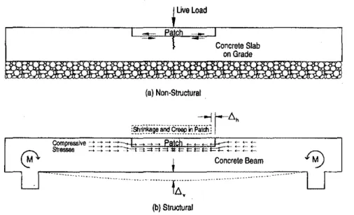
Fig. 2 - Typical nonstructural and structural repairs.
Cementitious Monan Cementitious MortarsPolymerwModified Resinous Mortars
Portland cement (PC) Styrene-butadiene rubber Epoxy
High alumina cement(HAC) Vinyl。」・エ。セ Polyester
PCIHAC mixtur
es
Magnesium phosphate AcrylicExpansion producinggrouts Acrylic Polyurethane
1 j
This is the predominant failure mode when the shear strength of the substrate
concrete is lower than the bond
strength at the interface and the tensile strength of the patch.
• Failure of the bond between the
re-pair material and the base concrete.
This takes place when the bond
strength at the interface is lower than the strength of both the base concrete and the repair material (Fig. Ie).
structural repairs, this phenomenon
can cause a loss of load-bearing ca-pacity. Clearly, the large number of
commercially available repair materi-als with wide variation in mechanical
properties makes proper selection of suitable repair materials a daunting
task - especially for harsh
environ-mental and loading conditions. The major criteria that should be con-sidered in the selection of patching
ma-terials for a given environment include in-service exposure conditions, logistic
considerations, patch installation
pa-rameters, and material characteristics.
In-service exposure
conditions
Some of the in-service exposure
condi-tions that should be considered in a re-pair program are listed below:
• Humidity and temperature
varia-tions. Temperature changes and cycles
of wetting and drying cause
dimension-al expansion and contraction. These conditions may generate tensile stress-es in excstress-ess of the repair materials
ten-sile capacity and thus cause cracking and debonding of the repair material.
• Freeze-thaw cycles. When saturated
and hardened concrete is exposed to low temperatures, the water held in the
Cementirious Polymer-Modified
Mortars Cementitious Resinous Mortars
Mortars 20'50 30-60 50-100 2-5 5-10 10-15 20-30 15-25 10-20 10 10-20 25-30 5-15 0.1-0.5 1-2 >300 tOO-300 40-80 35 Mechanical
PrUI!X'[lies
suring that the repair material is
com-patible with the substrate concrete is crucial, as the repaired member must behave monolithically and carryall stresses in the region of the repair
with-out distress or deterioration.
Selection of a compatible
and durable patching
material
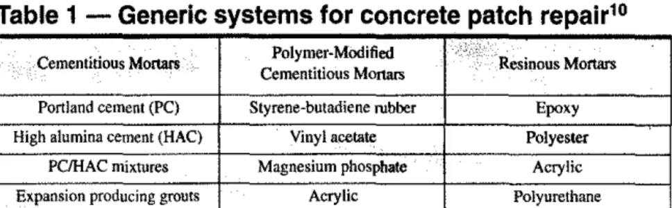
A wide variety of repair materials is now available to the design engineer.' These materials can be categorized into
three groups: cementitious mortars,
polymer-modified cementitious
mor-tars, and resinous mortars. As shown in
Table I, these groups can be further subdivided into generic types of repair products.
Table 2 shows typical values for some important properties for the three groups of repair materials. For a given mechanical property, a large difference in the values for the three different groups of repair materials can be observed. Such differences in the mechanical properties of two bonded materials can give rise to the development of initial tensile stresses as well as the formation of cracks at or near the interface, leading to the de-bonding of the repair material. In
Table 2 - Typical mechanical properties of repair materials
14March 1996
Types of repair: structural
and nonstructural
Although patching is widely used in the rehabilitation of structures, there is little differentiation shown between the types of materials used in
non-structural or non-structural repairs.
Con-crete patching materials are used in two different ways:
• nonstructural repairs, which
im-prove surface appearance, reduce
per-meability, protect reinforcement, or
improve abrasion resistance (Fig. 2a), and
• structural repairs, which restore the design load-bearing capacity of a dam-aged member, or improve the load-bearing capacity of an under-designed member (Fig. 2b).
Significant, or even excessive, stresses can develop in nonstructural
repairs just as easily as in structural
re-pairs. A proper repair design requires the correct combination of properties and dimensions of the bonded
materi-als in order to ensure that for
nonstruc-tural repairs, the interface bond
strength is not exceeded by stresses at the interface, and for structural re-pairs, the repair can carry its design load and allow for any volume chang-es which may take place over time in
service conditions.2
During the repair process and subse-quent curing period, failure to provide support to some of the external dead and live loads by jacking and shoring the memher undergoing repair may
re-sult in some of the internal stresses Compressiveウエイ・ョァセエィ⦅Hセmp⦅。セI
-1----,-,--+--:-:-:,--4--==--1
(which were transferred to the sur- Tensile strength (MPa)rounding substrate concrete when the Elastic modulusin
」ッNZNュMーイ・NNNNZNウMZウゥッMョセiMMM]]LMMKMMZMZMZZMZMMTMM]]MMQ
damaged concrete was removed) re- (GPa)
maining permanently in the substrate セ GGG[|エセFヲNGGッエエィ・エjiャ。ャ・クー。ョウゥッョ
concrete. In such a case, the・ヲヲ・」エゥカ・セ (oC-1 x10⁻⁶
ness in bearing and transmitting the .2.-
1--_-,-,__+_-:--:-0-_4__--:'-';:-__
stresses of the structural repair would Water absorption
be diminished or compromised. (percentby we..:ig:..h:..t)_ _
+__
=:-__I--_==::-_+-_-:=::-__
repaired beams of indeterminate
struc-tures cause redistribution of the
mo-ment (generated by the shrinkage force in the repair material) resulting in greater shrinkage than is found in
de-tenninate structures.4Therefore, where
shrinkage is likely to be restrained, a repair material with low shrinkage po-tential is required.
Material characteristics
Some of the most important properties to consider in the selection of a durable and compatible repair material are list-ed in Table 3 and discusslist-ed below. The reqnired relationship between the prop-erty of the repair material (R) and that of the substrate concrete (C) is identi-fied in parentheses for each property.• Shrinkage strain (R<C). In cement-based materials, most of the shrinkage occurs when the cement paste dries out after setting and hardening. In resin-based materials, shrinkage is a result of cooling following the exothermic reac-tion, particularly for patches with a thickness exceeding 15 rum (0.59 in.). When shrinkage is restrained (Fig. 2b),
permanent tensile stresses develop in the repair material and may cause
ten-Table 3 -
General
requirements of patch
repair materials for
compatibilit
y
lO(b)Extem.1 Load Parallel to the Inlenace
member depends, for the most part, on the strain capacity of the repair materi-al, while the performance of large structural patches depends on both the
strain and stress capacities of the repair
material over the service life of the structure.' For both large and small patches, high stresses can concentrate at edges and at changes in section, and may result in cracking at the bond inter-face and in the patch itself. Thus, a re-pair material with adequate tensile strength should be selected.
• Presence of reinforcement in the
re-pair. The effect of reinforcement on patch repairs is to reduce both the shear slress along the interface between the patch and the substrate as well as the
tensile stress in the substrate concrete.
,
,
,
Low Modulu.
,
,
HighModulu.,
HighModulu. Material
,
,
Mate,lal Matenal,
,
,
jJ,
jJ,
,
,
,
Moderate trans er e strass : Low load-bearing High axial stress :
concentration at inle ace I
,
effectiveness concentration IjJ,
:
,
Low Modulus Material
,
, ) Polenli.1セ
:,
tIe a). :
,,
(a) Extemalload Perpendicular 10 the Interface
Fig. 3 - Effects of mismatching elastic moduli.
capillary pores freezes and expansion occurs. Repeated freeze-thaw cycles have a cumulative effect, causing rapid degradation of the repair material.
• Impact, sustained, or cyclic loads.
Impact loads can cause the concrete to spall because of the different
wave-transmission rates of the material's
several constituents. Sustained loads
can induce additional strains in the
re-pair material because of the differential creep between Ihis material and the substrate concrete. Furthermore, cyclic loads can exceed the fatigue capacity of the repair material and cause its failure.
Logistic considerations
In many instances, the area to be paired may be inaccessible and mayre-quire the use of a self-leveling material Itcanalso provide a strong mechanical Relationship,of,
that flows easily. The repair may also anchorage for the repair material, re- .•• i"S;;,·.· •..•· •..··
..
セB
'itil/lf"
have to be done while the facility re- duce the distortion of the transverse in- ⦅GLUイュ[[ヲLセセwGQHB\GZ[LェセNBLセ[⦅_
mains openl necessitating the use of terface, and
eliminate concentrated
ii.","'·c'}:"·
.
tbconcretesubsttatefast products. These logistic stress zones near the interface.
Howev-(C)
cunng
considerations often dominate others in er, reinforcing bars can introduce new sbrir¢age-,s,ltwn R<C
the selection of repair materials. The problems: restraints imposed on move- Creep coefficient (for R<G
··;;·V"
growing trend for performance rather ment and increased pressure as the re- t:CpairsincOJnP!e§si()n)
than prescription specifications and life suit of corrosion can create large Creepcoefficient R>C
cycle costing may also dictate the use stresses which concentrate around the (for repairs.U:tension)
,'C:>
of low-maintenance repair systems, bars. For these reasons, it is important Thennal eXpansion R=C
to select a repair material that bonds coefficient
Patch installation
sile strength and low permeability.well to steel and that has adequate ten- Modulus of elasticity R=Cparameters
•
Effect ofsection stiffness. Additional Poisson's ratio R=CThe following parameters should be shrinkage stress can be generated in the Tensile strength R>C
considered dUring the design of the re- repair material of a stiff beam because f。エゥァオ・セイエZHIヲエャQスゥjQセセセ R>C
pair program. of the restriction of movement imposed
• Size and geometry of repair patches.
"Adhesibti
.'.'\
9.3·"·,
R>C
by the relatively small amount of
cur-The performance of small patches in- vature of this type of beam. Moreover, pッイッウNゥセ[セ[セェウLエゥカゥエケ R=C
traduced to restore durability to the differences in section stiffness along ChemlC'Ol'mtotNl.tYi R<C •..
Repair Material Subetrate Concrete
(b)later stages·high corrosionsctMtydueto uneven distribution of oxygen and chloride Ions
Fig. 4 - Effects of mismatching porosities.
CI-
cr
0, Substrate Concrete (highporosity) 0, 0, 0,I
I
I
Depletion of oxygen セ セ.+
al the interface OW OW OW セGMMMMセGMMMMGLセ- - _
..⦅MセMMMMMセcr cr
0,,
i Rapidciffusion of oxygen to the rebar and chloride
1ionsto the intenace due to higher permeability
0,
cr cr
(allnWaIstage·,qualCOfIC8Illralion ofoxygen,n<! chlorld'
lon, intllerepair materlal,ndsubstrateoonorete
R,palr Matarlal (low porosity)
Consumption of OWwillcause
thepH of concrete to decrease Fe(OH),
t t t
Fe++ Fe++ Fe++
t t t
Accumulation of positive charges
?
Aebarstress concentration and failure of the • Poisson's ratio (R=C).Poisson's
ra-high modulus materiaL' When the ex- tio controls the magnitude of the
trans-temal load is applied perpendicular to verse strain in relation to the strain in
the bond line (Fig. 3a), the difference in the direction of the applied uniaxial
stiffness between both materials is less loading. The effect of Poisson's ratio is
problematic if the eXlemalload is com- greatest when the bond interface is
per-pressive. However, if the perpendicu- pendicular to the direction of loading
larly-applied external load is tensile, and negligible when the load is parallel
mismatching elastic moduli is likely to to the interface,1O Bonded materials
cause adhesion failure. with mismatched Poisson's ratios can
The higher modulus material impos- generate differential transverse strains
es a severe constraint on the transverse at the bond line if the interface is
per-contraction of the lower modulus mate- pendicular to loading, causing cracking
riaL High concentrated stresses can at the interface. For this reason, it is
im-then locate in the lower modulus mate- P0rlant that both the substrate concrete
rial very close to the interface and ini- and the repair material have similar
tiate failure.9Therefore, when selecting Poisson's ratios.
a repair material, designers should en- • Tensile strength (R>C), A tensile
sure that both substrate concrete and force can be generated in a repair
mate-the repair material possess similar elas- rial by a combination of external
load-tic moduli. ing Hゥュー。」セ sustained and cyclic),
セMMイM
_ _----r_ _
37_1
sile cracking in the material itself, ordelamination at the interface of the
re-pair material and the substrate,5Since
most repair materials are appliedtoan
older substrate concrete tbat has negligible shrinkage, the repair material -which will begin to shrink soon after
casting - must have very low
shrink-age potential.'
• Creep coefficient (R<C or R>Cj,
Creep is the continuous deformation of a member subjected to a sustained
ap-plied load,It can result in reduced
load-bearing effectiveness in the repair ma-terial and also result in load transfer from the repair material to the substrate
concrete, or to a nonstructural element.
In the case of structural repairs loaded in compression (Fig, 2b), the
repairma-terial must possess very low creep
po-tentiaL On the other hand, in the case of repair patches loaded in tension, creep can be beneficial, as it can reduce or cancel the adverse effect of shrinkage
in the repair materiaL7
• Thermal expansion coefficient
(R=C), The coefficient of thermal
ex-pansion is a measure of the change of length in a material when it is subjected
to a change in temperature. When two
materials of different coefficients of thermal expansion are joined together and subjected to significant
tempera-ture changes, stresses are generated in
the composite material. These stresses may cause failure at the interface or in the lower strength material. This is par-ticularly evident in meat processing plants where floors are coated with ep-oxy toppings, Steam cleaning of the floors causes the topping (which has a higher thermal expansion coefficient) to shear off at the interface, Unless the temperature change is expected to be very small, the repair material should possess a thermal expansion coefficient similar to that of the substrate concrete,
• Modulus of elasticity (R=C), The
elastic modulus is a measure of rigidi-ty; low modulus materials deform more than those of high modulus under a giv-en load, Whgiv-en the external load (com-pressive or tensile) is applied parallel to the bond lin" (Fig, 3b), materials with different elastic moduli will transfer stresses from the low modulus material (lower load-bearing effectiveness) to the high modulus material, leading to
March 1996 e '1
,-a s ,I "Selected for reader interest by the editors. volume changes (shrinkage, creep, and
temperature and humidity variations) and mismatches in the properties of the repair material and the substrate con-crete, When any of these forces pro-duce a tensile stress in excess of the repair material's tensile capacity, fail-ure of the material can be expected in the form of tensile cracks, spalling or debonding, Thus, tensile strength -perhaps even more than compressi ve
strength - is an important property to
consider when selecting an appropriate material for a repair project.
• Fatigue peiformance (R>C), Be-cause cyclic loading Be-causes progressive
development and propagation of
cracks, the fatigue strengthofa materi-al is less than its static strength. The number of loading cycles a repair mate-rial can withstand decreases rapidly as the level of stress increases. Unless the repair material is expected to experi-ence only a negligible level of stress, it must have properties that can provide sufficient fatigue performance.
• Adhesion (R>C). Provided that an
adequate match of the bonded materi-als exists, any improvement of the bond will increase the performance of the composite system. Repairs with bond
lines in direct tension have a greater
de-pendency on bonding than do repairs with bond lines in shear, which benefit from the aggregate interlock mecha-nism. The bond strength at the interface can be influenced by the properties of the substrate concrete and its surface
(roughness, cleanness, and curing
state), by the properties of the repair material, including absorption and its ability to adhere to the substrate, and by environmental conditions.I I
• Porosity and resistivity (R=C). The
porosity and resistivity of the patching material may also affect the durability of the patch (Fig. 4). When materials that are dense, impermeable, highly re-sistive. or nonconductive are used, there is a tendency for the repaired area to become isolated from adjacent un-damaged areas. Consequently, there is a large porosity or chloride content dif-ferential between the patched area and the rest of the concrete which, in turn, causes lhe current from the resultant corrosion to become concentrated in a restricted area. The rate of steel corro-sion may then be accelerated, causing premature failure in either the patch or the adjoining concrete." Therefore,
38
when selecting a repair, it is important to ensure that both the substrate con-crete and the repair material possess similar porosities or densities.
• Chemical reactivity (R<C). The
re-activity of the patching material with steel reinforcement and other embed-ded metals, with the aggregate in the concrete, or with specific sealers or protective coatings applied over the patch must also be considered. Patch-ing materials with low to moderate pH provide little protection to concrete while highly alkaline material may at-tack potentially reactive aggregates in the concrete. Therefore, the reactivity of patching materials with both the sub-strate and the surface protection
prod-uct should be checked.3
•!3
Summary
The lack of comprehensive data on the performance of repair products and on the potential incompatibility between repair materials and substrate concrete is at least partly responsible for the large number of premature repair fail-ures in North American concrete struc-tures. Effective and durable repairs can be realized only when a detailed diag-nosis of the causes of deterioration has been made and given full consider-ation in the selection of materials that are both suitable for the particular en-vironment and service conditions, and compatible with the intended
sub-strates. It is the responsibility of the
design engineer to ensure that the se-lected repair material has these quali-ties so that it will last for the intended life of the repair.
References
1. Emmons, P.R and Vaysburd, A.M, "Factors Affecting the Durability of Concrete Repair: The Contractors Viewpoint," Construction and
Build-ing Materials, 80),1994,pp.5-16.
2. Plum, D.R., "The Behavior of Polymer Ma-terials in Concrete Repair, and Factors Influenc-ing Selection," The Structural Engineer, 68(17), 1990. pp. 337-345.
3. Mailvaganam, N.P., Repair and Protection
of Concrete SmKtures,eRePress, Boca Raton, 1992, pp. 47J.
4. Yuan, Y-S. and Marosszeky, M., "Re· strained Shrinkage in Repaired Reinforced Con-crele Elements," Materials and Structures, 27, 1994, pp. 375·382.
5. Yuan, Y.-S. and Marosszeky. M., "Major Factors Influencing the Perfonnance of
Structur-。! Repair," ACI Special Publication SP-J28·50, 2.1991, pp. 819-837.
6. Brill, L., KomIos, K., and Majzlan, B.. "Ear-ly Shrinkage of Cement Paste. Mortars and
Con-crete," Materials and Structures, 13(73), 1980. pp.41-45.
7. Saucier, E, Detriche. c.H.. and Pigeon. M .• "Tensile Relaxation Capacity of a Repair Con-crete," Materials and Structures, 25, 1992. pp. 335-346 (in French),
8. Hewlett, P.c. and Hurley, S.A., The
Conse-quences of Polymer-Concrete Mismatch, Design Life of Buildings, Thomas Telford, London,
1985, pp. 179·196.
9. Good, R. 1., Locus of Failure and its
Impli-cations for Adhesion Measurements, Adhesion Measurement ofThin Films, Thick Films, and Bulk Coatings, ASTM STP 640, K.L. Minai, Ed.•
American Society for Testing and Materials, 78, 1978. pp. 18-29.
10. Emberson, N.K. and Mays, G.C., "Signifi-cance of Property Mismatch in the Patch Repair of Structural Concrete - Part I: Properties of Re-pair Systems," Magazine of Concrete Research, 42(152),1990. pp. 147-160.
II. Saucier,F. and Pigeon, M., Durability of
New-to-Old Concrete Bondings, ACI Special
Publication SP-l2843, I, 1991, pp. 689"705. 12. Gu, P., Fu, Y.• Xie, P.• and Beaudoin, J.J.• "Effect of Uneven Porosity Distribution in Ce" ment Paste and Mortar on Reinforcing Steel Corw
rosion," Cement and Concrete Research,24(6),
1994, pp. 1055-t064.
13. Mailvaganam, N.P., "Studies Aim at Un-derstanding Why Concrete Patches Fail," MaJew
rial News, Material Laboratories, Institute for
Research in Construction, National Research Council Canada, spring1994,p.4.
14.Mays, G. and Wilkinson, W., Polymerr・セ
pairs to Concrete: their Influence on Structural Performance, ACI Special Publication SP-l()()..
22.1,1987. pp. 35t-375.
Daniel Cusson is .a research afllllXli-""
ate with the Re- C
pair Technologies and Strategies. ,,",' lq;roup atlhe Na- ','
tional Research Council's Institute
nstruction
ftom the Univer
ャセᆪNゥ[ヲ
Canada and completed a post-dOC-toral fellowship In Paris on the con-finement of high-strength concretll cohimhs, ,:.
",;K'\c?%k';i.'
Noel Mallvagan-am is a senior re-search officer with the Repair Tech-nologies and Strategies Group at the National Research
Coun-cil'siョゥゥエャiオエャゥセGャGi・ウャャャAセ iセ
Con-struction (NRC/IRC).
Hills
active inCSA, ACl;and
AILEM
committeeson repairs and.isthe author of books
on。、ャャIャNis|NセセャAAセエイウL