Characterization of light and heavy hydrated
magnesium carbonates using thermal analysis
The MIT Faculty has made this article openly available.
Please share
how this access benefits you. Your story matters.
Citation
Unluer, C., and A. Al-Tabbaa. “Characterization of Light and Heavy
Hydrated Magnesium Carbonates Using Thermal Analysis.” Journal
of Thermal Analysis and Calorimetry 115.1 (2014): 595–607.
As Published
http://dx.doi.org/10.1007/s10973-013-3300-3
Publisher
Springer Netherlands
Version
Author's final manuscript
Citable link
http://hdl.handle.net/1721.1/103139
Terms of Use
Article is made available in accordance with the publisher's
policy and may be subject to US copyright law. Please refer to the
publisher's site for terms of use.
1
Characterization of light and heavy hydrated magnesium carbonates using thermal analysis C. Unluera.*., A. Al-Tabbaab
a CSHub, Department of Civil and Environmental Engineering, MIT, 77 Massachusetts Avenue, Cambridge,
MA 02139, USA
b Department of Engineering, University of Cambridge, Trumpington Street, Cambridge, CB2 1PZ, United
Kingdom
* Corresponding author. Tel.: +1 617-901-8501, E-mail address: cise@mit.edu
Abstract:
Upon heating, hydrated magnesium carbonates (HMCs) undergo a continuous sequence of decomposition reactions. This study aims to investigate the thermal decomposition of various commercially produced HMCs classified as light and heavy, highlight their differences, and provide an insight into their compositions in accordance with the results obtained from thermal analysis and microstructure studies. An understanding of the chemical compositions and microstructures, and a better knowledge of the reactions that take place during the decomposition of HMCs was achieved through the use of SEM, XRD, and TG/DTA. The quantification of their CO2 contents was provided by TG and dissolving the samples in HCl acid. Results show that variations exist
within the microstructure and decomposition patterns of the two groups of HMCs, which do not exactly fit into the fixed stoichiometry of the known HMCs in the MgO-CO2-H2O system. The occurrence of an exothermic
DTA peak was only observed for the heavy HMCs, which was attributed to their high CO2 contents and the
relatively delayed decomposition pattern.
2
1. Introduction
Intergovernmental Panel on Climate Change (IPCC)’s Fourth Assessment Report [1] states that green house gas emissions have increased by an average of 1.6% per year over the last three decades and presents different scenarios that would facilitate the stabilization of carbon dioxide (CO2) concentration within the 450-750 ppmv
range. To achieve this, cumulative emissions ranging from 1500 to 3500 GtCO2 need to be captured during this
century. Various methods providing permanent and safe storage of CO2 have been proposed, one of which is
mineral carbonation, involving the synthesis of minerals via reaction of CO2 with Mg-Ca silicate rocks or
hydrated magnesium carbonates [2-5].
Due to their ability to sequester anthropogenically generated CO2 in a stable and long-lasting form, magnesium
carbonates are currently of great interest as a part of the efforts to counter global warming, where the main goal is to capture and store excess CO2, preventing its accumulation in the atmosphere and therefore slowing down
its contribution to climate change. Magnesium carbonates exist in two main forms: hydrated and unhydrated. Unhydrated magnesium carbonate naturally exists as a geological material in its anhydrous carbonate form, magnesite (MgCO3). First discovered in 1808, magnesite is the primary mineral in igneous and sedimentary
rocks. It also occurs in hydrothermal ore veins and oceanic salt deposits. There are two physical forms of magnesite, cryptocrystalline or amorphous magnesite; and crystalline, macrocrystalline or bone magnesite. Its essential elements include carbon (C), magnesium (Mg), and oxygen (O), whereas the common impurities are iron (Fe), manganese (Mn), calcium (Ca), cobalt (Co), and nickel (Ni). Decomposition of magnesite takes place at elevated temperatures, resulting in the formation of magnesium oxide (MgO) and carbon dioxide (CO2):
MgCO3 (s) MgO (s) + CO2 (g)
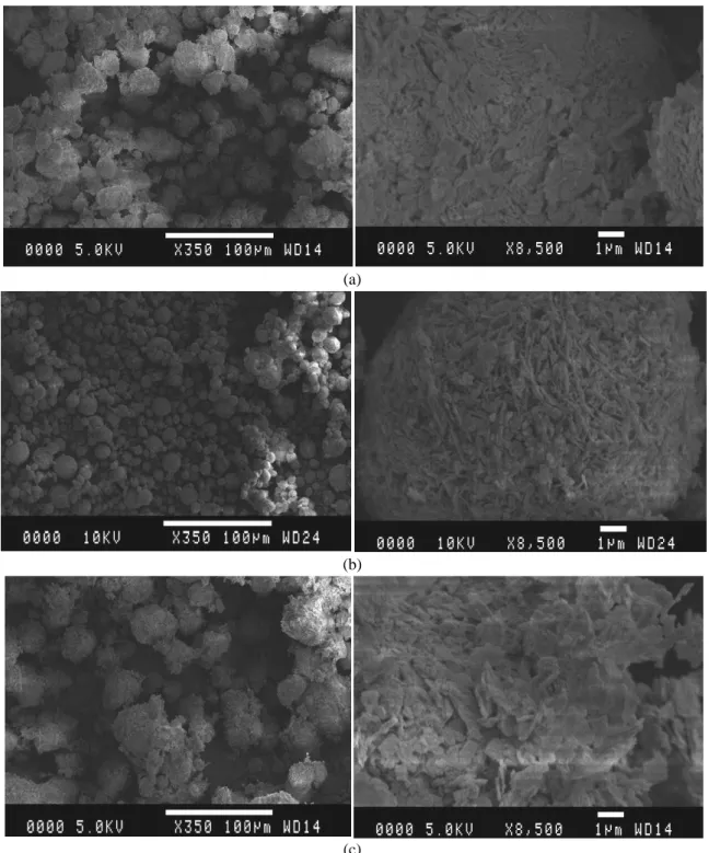
Hydrated magnesium carbonates (HMCs), or magnesium hydroxyl-carbonates, include 40-50% MgO in their formulations and can be defined with the general formula, xMgCO3.yMg(OH)2.zH2O. SEM micrographs of
typical HMCs are shown in Fig. 1. There are two main forms: Light (LHMC), with the empirical formula 4MgCO3.Mg(OH)2.4H2O, corresponding to hydromagnesite; and heavy (HHMC), with the empirical formula
4MgCO3.Mg(OH)2.5H2O, corresponding to dypingite [6]. The light form is 2-2.5 times more bulky than the
heavy. Common uses of these HMCs are in the pharmaceutical, cosmetics and rubber industries, where they are employed as carriers and retainers of products, and as reinforcing agents [7].
Various methods exist for the production of both forms of HMCs [8-12], such as from the calcination of dolomite [13] or from mixing magnesium sulfate or chloride solution with sodium carbonate solution. The light form, also referred to as magnesia alba levis is produced by precipitating in a cold solution; whereas performing this process in a boiling solution leads to the formation of the denser magnesia alba ponderosa, also known as the heavy form.
Although the properties and formation of magnesium carbonates have been widely studied, questions still remain in regard to the complexity of the magnesium carbonate system involving various forms of HMCs. Therefore, the properties and formation of a range of carbonates within the MgO–CO2–H2O system are still not
fully understood mainly due to the complexity of the system, but the stability of HMCs has been studied by many researchers [6, 14, 15, 8, 16-21]. Accordingly, magnesite and brucite are the only stable products in the MgO-CO2-H2O system. Other HMCs form in the system depending on the water content, temperature and the
CO2 concentration they are exposed to. An increase in temperature leads to the transformation of carbonates into
those that are less hydrated than others, whereas a change in CO2 concentration also results in the formation of
different phases [20].
The formation of a range of HMCs observed within MgO-CO2-H2O system is listed in Table 1, depending on
the number of Mg ions they contain within their structures. Having a lower stability field of CO2 concentration
than nesquehonite [22], lansfordite decomposes into nesquehonite when the temperature is above 10 ˚C [8, 17]. At a temperature above 50 ˚C, nesquehonite, whose stability is influenced by the loss of water from the system resulting in the decrease of water activity, transforms into hydromagnesite [8, 21]. However, it has also been stated by Davies and Bubela [15] that protohydromagnesite, a phase similar to dypingite, appears as an
3
intermediate step before hydromagnesite, also confirmed by Botha and Strydom [6] and Power et al. [18]. Canterford et al. [14] stated that a range of intermediate phases between nesquehonite and hydromagnesite may form according to the following equation, where x can range between 4-8 and 11. The resulting component in this equation would correspond to dypingite and giorgiosite when x is equal to 5 and 6, respectively. Finally, hydromagnesite is transformed into magnesite under elevated temperatures (e.g. 126 ˚C) [19]. This
transformation was found to be possible both in ambient and accelerated CO2 atmospheres, although the latter
was seen to trigger the process.
5(MgCO3·3H2O) Mg5(CO3)4(OH)2·xH2O + CO2 + (15-(x+1))H2O [14]
Thermoanalytical techniques such as Differential Thermal Analysis (DTA) and Thermogravimtery (TG) are useful tools in the characterization of raw materials and determination of their fundamental thermodynamic parameters [23-25]. A thermal change taking place during DTA represents either an absorption (endothermic reaction) or release (exothermic reaction) of heat during the temperature interval. The investigation of the hydration and carbonation mechanisms with thermal analysis makes use of the fact that during heating, the cement paste undergoes a continuous sequence of more or less irreversible decomposition reactions [26].
(a) Magnesite [27] (b) Nesquehonite [28]
(c) Dypingite [18] (d) Hydromagnesite [29]
Fig. 1 SEM images of some of the most common magnesium carbonates
When subjected to thermal analysis, HMCs decompose by an endothermic reaction and result in the emission of H2O and CO2. Several studies [6, 30-32] have investigated the thermal decomposition steps of hydromagnesite
and dypingite. According to Sawada et al. [32], the thermal decomposition of hydromagnesite proceeds via dehydration at 100-300°C and decarbonation at 350-650°C toward the end product, MgO. A sharp exothermic peak accompanied with a pronounced mass loss was found at around 500°C during the decarbonation process, referring to the amorphous magnesium carbonate crystallizing to magnesite. During this a rapid evolution of CO2 was observed, explaining the sharp mass loss [8, 33, 21, 34, 11, 12, 32]. According to Dell and Weller [8],
4
atmosphere in which the basic magnesium carbonate loses water to form an amorphous product, followed by the loss of CO2 endothermically. Khan et al. [7], has shown that certain factors such as the heating rate, sample size,
and atmospheric conditions used during thermal analysis influence the exothermic peak. Therefore, these factors were kept constant during the study presented here to observe the occurrence of the exothermic peak for different HMCs.
Table 2 summarizes the steps during the thermal decomposition cycles of these carbonates, where the main component remaining after a complete cycle of thermal decomposition is 5MgO, representing 43.2% and 41.5% of hydromagnesite and dypingite, respectively. Therefore, 56.8% of the initial total mass of hydromagnesite and 58.5% of dypingite is lost during thermal decomposition, as shown in Table 2. In this particular study, TG/DTA, provides a valuable tool for determining the composition of commercially produced HMCs by investigating the H2O and CO2 emitted during the decomposition of the HMCs into MgO.
The aim of this work is to investigate the decomposition of various commercially produced HMCs, shed light on the differences between light and heavy HMCs, and provide an insight into their compositions in accordance with the results obtained from thermal analysis and microstructure studies. The attributions of the different stages associated with thermal analysis are discussed, highlighting deviations from values stated in the literature and the presence of the exothermic phenomenon in the case of heavy HMCs. In addition to thermal analysis, X-ray diffraction (XRD), scanning electron microscopy (SEM), and quantification of CO2 content by hydrochloric
(HCl) acid digestion are used to distinguish between the various HMCs. This research presents the possibility of identifying previously unidentified HMCs whose chemical compositions do not exactly fit into the fixed stoichiometry of the known HMCs within the MgO-CO2-H2O system.
Table 1
Compounds forming in the MgO-CO2-H2O system [35]
Groups No. of MgO moles
No. of H2O
moles
No. of CO2
moles Compound Chemical formula
1 - Brucite Mg(OH)2 - 1 Magnesite MgCO3 Group I 1 2 1 Barringtonite MgCO3·2H2O 3 1 Nesquehonite MgCO3·3H2O 5 1 Lansfordite MgCO3·5H2O Group II 2
1.5 1 Pokrovskite Mg2(CO3)(OH)2·0.5H2O
4 1 Artinite Mg2(CO3)(OH)2·3H2O
Group
III 5
5 4 Hydromagnesite Mg5(CO3)4(OH)2·4H2O
6 4 Dypingite Mg5(CO3)4(OH)2·5H2O
6-7 4 Giorgiosite Mg5(CO3)4(OH)2·5-6H2O
Group
5
Table 2
Thermal decomposition steps of hydromagnesite (H) and dypingite (D) [31]
Step Action Reaction Leaving
mineral Mass loss/% Temp. /°C DTA peak /°C
Dehydration removal of water of crystallisation 4MgCO3·Mg(OH)2·4H2O 4MgCO3·Mg(OH)2 + 4H2O 4H2O (H) 15.4 (H) <250 54 5H2O (D) 18.5 (D) Dehydroxylation decomposition of Mg(OH)2 to MgO 4MgCO3·Mg(OH)2 4MgCO3 + MgO + H2O H2O 3.8 (H) 250-350 259 3.7 (D) Decarbonation decomposition of MgCO3 to MgO
4MgCO3 4MgO + 4CO2 4CO2
37.6 (H) >350 433 and 520 36.3 (D)
2. Materials and methods
Seven different HMCs, acquired from various companies as listed in Table 3, were investigated as a part of this study. Out of these 7, the first 3 (i.e. #1, 2 and 3) were characterized as heavy, whereas the rest (i.e. #4, 5, 6, 7) were light HMCs. Each group was produced through different processes, leading to dissimilarities within the products due to the varying experimental conditions. According to the supplier, LHMCs were precipitated from carbonating a slurry of brucite, forming bicarbonates which were then heated. HHMCs were obtained through precipitation from mixing NaCO3 with MgSO4 and are usually coarser than LHMCs. The microstructure of
representative samples from each HMC was observed by using a scanning electron microscope, JEOL JSM-5800 LV. X-ray diffraction (XRD) was utilized to provide qualitative and quantitative analyses of the crystalline phases present within the mixes. XRD analysis was conducted on a Siemens D500 Diffractrometer. The relative diffraction peaks of various HMCs were identified by using X-ray diffraction analysis under the operating conditions of Cu Kα radiation (40 kV, 40 mA). The instrument used for TG/DTA was a Perkin Elmer STA 6000, controlled by Pyris software. To start the analysis, the powder was placed in a ceramic crucible designed for use with the instrument. TG/DTA was carried out where the samples were heated in air from 40 °C to 800 °C at a rate of 10 °C/minute. The tests were performed under an air flow of 50 ml/min. The change in mass with the increasing temperature was recorded to provide qualitative and quantitative information. Another method to measure the quantity of CO2 absorbed during carbonation was by acid digestion using HCl acid. This process
involved decomposition of the carbonates by reacting them with HCl acid, explained by the following reactions: MgCO3 + 2HCl MgCl2 + CO2 + H2O
6
Table 3
List of all HMCs analyzed in this study
No Company Material Description (provided by the supplier)
1 Sigma-Aldrich Magnesium carbonate basic, heavy, ≥40% MgO
2 Sigma-Aldrich Magnesium carbonate hydroxide hydrate
3 Fisher Chemicals Magnesium carbonate, hydrated basic heavy
4 Acros Organics Magnesium carbonate hydroxide, light, 40-45% MgO
5 Fisher Chemicals Magnesium carbonate, hydrated basic light
6 Riedel-de Haen Magnesium carbonate basic, light, powder, ≥40% MgO
7 Acros Organics Magnesium carbonate, light
3. Results and discussion
The discussion on the classification of the basic magnesium carbonate products will be structured in four main parts, focusing on the microstructure, x-ray analysis, thermal decomposition, and CO2 content quantification of
the seven different HMCs.
3.1. Microstructure
Figs. 2 and 3 show the SEM micrographs of the dry powders of HMCs used at two different magnifications (x350 and x8500), presenting different arrangements of particles within each carbonate and highlighting the differences between LHMCs and HHMCs. These images illustrate the porous nature of the HMCs in general. The HHMCs (Figs. 2(a)-(c)) have a relatively dense microstructure, when compared to those of the LHMCs (Figs. 3(a)-(d)). The differences can further be seen in the way in which the flakes are arranged within the materials, where the HHMCs exemplify an impenetrable structure while LHMCs have a more widely dispersed arrangement of the flakes. While the first three HHMCs (i.e. #1, 2, and 3) and last three LHMCs (i.e. #5, 6, and 7) have very similar microstructures, LHMC #4 has a distinctly more porous structure with smaller particle sizes, even when compared to the other LHMCs. This feature is also reflected by the relatively high standard consistence of this specific HMC, measured as 2.64, compared to an average of 0.7 for the HHMCs and <2.0 for the other LHMCs [36].
3.2. X-Ray analysis
The XRD diffractograms of the HMCs used in this work are shown in Fig. 4, indicating the 2 Theta locations of different intensity peaks for each compound. The similarities between the diffractograms of the different HMCs are clear, presenting a challenge when differentiating between each HMC.
Figs. 5(a) and (b) show the XRD patterns of HHMCs and LHMCs used in this study, respectively. All diffraction peaks are in good agreement with the reported data by the Joint Committee on Powder Diffraction Standards (JCPDS 25-513) of well crystallized hydromagnesite. The main characteristic peaks of this specific HMC, shown by the vertical lines on the bottom of Fig. 5, are located at 15.3˚, 30.8˚, and 39.2˚ 2Theta. Even though these HMCs were categorized under two separate groups of hydromagnesite (LHMCs) and dypingite (HHMCs), the XRD diffractograms reveal similar crystalline patterns for all the 7 HMCs, as it would be expected from Fig. 4, where the considerable overlap between the main peaks of hydromagnesite and dypingite is evident. However, some significant differences are observed in the crystalline patterns of both groups of HMCs. In the case of HHMCs, HMC#2 indicates a unique peak at 2θ = 18.7˚, along with a double peak at 38˚, both corresponding to the characteristic peaks of Mg(OH)2. Alternatively, amongst the LHMCs, HMC#4 has
higher peaks than the other LHMCs at 2θ = 37.2˚ and 43.8˚. These variations also correspond to the different arrangement of particles in the microstructures of these particular HMCs, as explained in Section 3.1.
7 (a)
(b)
(c)
8 (a)
(b)
(c)
(d)
9
10 (a)
(b)
Fig. 5 XRD diffractograms of (a) heavy and (b) light HMCs
0
500
1000
1500
2000
2500
3000
3500
5
15
25
35
45
In
te
n
s
it
y
/a
.u
.
2 Theta/degree
0
500
1000
1500
2000
2500
3000
5
15
25
35
45
In
te
n
s
it
y
/a
.u
.
2 Theta/degree
#4
#5
#6
#7
#1
#2
#3
11
3.3.Simulaneous thermogravimetric analysis and differential thermal analysis
In this study TG/DTA was used to quantify the concentration distributions of Mg(OH)2 and MgCO3 within the
seven differentHMCs, each of which contains a certain percentage of CO2 and H2O that decompose at different
temperatures. Figs. 6(a) and (b) demonstrate the characteristic curves of TG/DTA for the heavy and light HMCs, respectively. The change in mass and the heat flow applied as a function of temperature are indicated,
highlighting the difference between the behaviors of the various HMCs when subjected to a constant rate of heating. Percentage mass loss of each HMC at different peaks is shown in Tables 4(a) and (b). There are three possible scenarios that would correspond to the results obtained from thermal analysis: (i) the decomposition pattern of the HMCs takes place according to the three steps and the temperature ranges stated in the literature, as expressed in Table 2, but the composition of the HMCs tested varies from those of hydromagnesite and dypingite listed in Table 1, (ii) the tested HMCs have the same or very similar compositions as hydromagnesite and dypingite but illustrate a decomposition pattern that does not necessarily fall within the given ranges in Table 2, or (iii) both the decomposition pattern and the composition of HMCs show variations to those stated in literature.
In accordance with the first scenario, data obtained from this analysis, listed in Table 4, demonstrate that the chemical compositions of these HMCs do not exactly fit into the fixed stoichiometry provided in Table 1. In addition to the variations amongst the production methods and atmospheric conditions, impurities within the HMCs may have led to slight differences in the formulations. When compared to hydromagnesite (i.e. 4MgCO3·Mg(OH)2·4H2O containing 5MgO+ 5H2O+ 4CO2) and dypingite (i.e. 4MgCO3·Mg(OH)2·5H2O
containing 5MgO+ 6H2O+ 4CO2), following the same temperature ranges presented in Table 2 and assuming
that all the mass loss was due to the loss of H2O and CO2 within the HMCs, the compositions of the seven
HMCs were found to contain between 3.6-5.3 H2O and 4.2-5.0 CO2. A list of the proposed compositions for all
seven HMCs is provided in Table 5. Similar to the findings of the XRD analysis in Section 3.2, these results suggest a stronger link to hydromagnesite since all the HMCs contain less water than dypingite. However it must be noted that the CO2 content of the tested HMCs was found to be higher than both hydromagnesite and
dypingite. The relatively high water content of HMC#7 as opposed to other HMCs was also reflected in the high total mass loss (i.e. 59.3%). Based on these values, it is highly likely that HMC#7 has a chemical formula resembling dypingite since the total mass loss at the end of the thermal decomposition of dypingite (i.e. 58.5%) is closer to the obtained value of 59.3% than that of hydromagnesite (i.e. 56.8%). The similarities between HMCs #4, 5, and 6 in both temperature ranges shown in Table 4 reveal their similar chemical composition and structure, which demonstrated identical decomposition patterns at each step.
Discrepancy in terms of the chemical composition of HMCs was reported in other studies [17]. One good example to this disagreement is the formula of hydromagnesite, which was given as 4MgCO3·Mg(OH)2·4H2O
[37, 38], whereas other studies confirmed it to have the chemical formula of 3MgCO3·Mg(OH)2·3H2O [39]. The
initial mass loss of all the HMCs at 259-285˚C, ranging between 9.6-16.1%, is much less than the values stated in the literature [6, 30, 31] for the dehydration and dehydroxylation steps (i.e. a total of 22.2% for dypingite and 19.2% for hydromagnesite). This means that not all the water molecules left the system at one single step and this continued until the temperature ranges shown in Table 6 were reached, which leads to the second scenario where the HMCs are assumed to have similar compositions to hydromagnesite and dypingite but follow a different decomposition pattern. As shown in Table 6, where the temperature ranges and associated mass loss that was caused by the loss of H2O and CO2 are indicated, in the case of HHMCs, the removal of water of
crystallization (i.e. 5H2O) was not completed until 350-395˚C, as opposed to the upper limit of 250˚C suggested
by Choudhary et al. [31] for hydromagnesite. This was followed by the decomposition of brucite into MgO, which was completed at 411-417˚C as opposed to 250-350˚C, followed by the final decarbonation step involving the decomposition of HMCs into MgO.
For LHMCs, the removal of initial water of crystallization took place before ~330˚C for HMCs #4, 5, and 6, whereas the same dehydration step took place earlier at 286˚C for HMC#7, as listed in Table 6(b). The same scenario was valid for the dehydroxylation step where brucite decomposed into MgO at ~380˚C for HMCs #4, 5, and 6, and earlier at 342˚C for HMC#7, thereby influencing the starting temperature for the decomposition of magnesite into MgO. HMCs #6 and 7 resulted in a slightly higher total mass loss than that of hydromagnesite (i.e. 56.8%), indicating the presence of extra H2O or CO2, as supported by the proposed formulations in Table 5.
12
The three steps involving the removal of water of crystallization, decomposition of brucite to MgO, and decomposition of MgCO3 to MgO are indicated by distinct endothermic peaks on the DTA curve in Figure 6,
also showing the temperature at which these reactions were completed. The removal of water of crystallization and decomposition of brucite to MgO are indicated by the same peak, followed by the next step of
decarbonation, where a larger peak corresponds to a higher degree of carbonation. The LHMCs indicated endothermic peaks at ~266°C and ~460°C. The first peak was due to the removal of water of crystallization followed by the decomposition of brucite into MgO, whereas the second peak indicated the decomposition of magnesite into MgO. On the other hand, the HHMCs indicated two endothermic peaks at 259-285°C, 413-475°C, and an exothermic peak at 517-525°C. These peaks were in accordance with those suggested by Botha and Strydom [30], taking place at 259˚C, 433˚C, and 520˚C. The first two of these peaks referred to the decomposition of brucite to MgO, and the decomposition of magnesite to MgO, respectively.
The exothermic peak at 520°C, stated to be prominent due to the crystallization of magnesite from the
amorphous phase as mentioned in Section 1, was only apparent in the case of HHMCs and not LHMCs. All the procedural variables that were found to affect the origin of the exothermic peak by Khan et al. [7], such as heating rate, sample size, and atmospheric conditions, were kept constant in this study and therefore did not contribute to the occurrence of the aforementioned peak. One possible explanation for the appearance of the exothermic peak only for the HHMCs could be due to their relatively higher CO2 contents, especially for HMCs
#2 and 3, which is explored further in Section 3.4. As the amount of CO2 released during thermal decomposition
increases, a higher strain is induced on the crystal lattice by the stress related to the volume change, changing the solid-state lattice. Any difficulty that the CO2 experiences while trying to escape leads to an explosion in the
material and release of strain in the form of heat, therefore producing the exothermic peak. The formation of the exothermic peak may have also been triggered by the relatively delayed start of the decarbonation process at 417°C in the case of HHMCs, when compared to that of LHMCs at 386°C, contributing to the overall strain applied.
Table 4
Percentage of mass loss during TG/DTA of (a) heavy and (b) light HMCs (a) Step HMC#1 HMC#2 HMC#3 Peak Temperature/˚C Mass Loss/% Peak Temperature/˚C Mass Loss/% Peak Temperature/˚C Mass Loss/% 1 285 16.1 259 9.6 275 12.9 2 441 18.2 413 & 475 17.3 & 15 437 26 3 518 18.7 525 9 517 12.8
Mass Loss Due to CO2/% 36.9 41.3 38.8
(b) Step HMC#4 HMC#5 HMC#6 HMC#7 Peak Temp./˚C Mass Loss/% Peak Temp./˚C Mass Loss/% Peak Temp./˚C Mass Loss/% Peak Temp./˚C Mass Loss/% 1 266 10.1 267 10.8 260 11.4 266 13.3 2 458 37.6 460 36.6 454 37.2 469 36.5
Mass Loss Due to CO2 /%
13
Table 5
Proposed composition of HMCs according to TG HMCs / Mass
loss/% <250˚C 250-350˚C >350˚C Total Proposed formulation
#1 6.3 12.2 39.8 58.3 5.0MgO·5.0H2O·4.4CO2 #2 5.5 7.9 45.1 58.4 5.0MgO·3.6H2O·5.0CO2 #3 6.1 10.1 41.4 57.6 5.0MgO·4.2H2O·4.4CO2 #4 6.8 9.7 40.8 57.3 5.0MgO·4.3H2O·4.3CO2 #5 6.2 9.9 39.9 56.0 5.0MgO·4.2H2O·4.2CO2 #6 8.0 9.7 41.1 58.8 5.0MgO·4.8H2O·4.5CO2 #7 10.6 9.1 39.6 59.3 5.0MgO·5.3H2O·4.4CO2 Table 6
Breakdown of total mass loss of (a) heavy and (b) light HMCs (a)
Mineral / Theoretical Mass Loss/%
Temperature/˚C
Component HMC#1 HMC#2 HMC#3
18.5 5H2O <350 <395 <387
3.7 H2O 350-411 395-411 387-417
36.3 4CO2 411-800 411-800 417-800
Total Mass Loss/% = 58.5 58.3 58.4 57.6
(b)
Mineral / Theoretical Mass Loss/%
Temperature/˚C
Component HMC#4 HMC#5 HMC#6 HMC#7
15.4 4H2O <331 <335 <313 <286
3.8 H2O 331-386 335-386 313-373 286-342
37.6 4CO2 386-800 386-800 373-800 342-800
14 (a)
(b)
Fig. 6 Characteristic curves of TG/DTA for (a) HHMCs #1-3 and (b) LHMCs #4-7 40 50 60 70 80 90 100 -80 -60 -40 -20 0 20 40 40 80 120 160 200 240 280 320 360 400 440 480 520 560 600 640 680 720 760 800 M a s s /% H e a t F lo w /m W Temperature/˚C #1 #2 #3 40 50 60 70 80 90 100 -80 -60 -40 -20 0 20 40 40 80 120 160 200 240 280 320 360 400 440 480 520 560 600 640 680 720 760 800 M a s s /% H e a t F lo w /m W Temperature/˚C #4 #5 #6 #7 En d o th e rm ic Ex o th e rm ic En d o th e rm ic Ex o th e rm ic
15
3.4. CO2 content
Two methods were primarily employed to measure the CO2 content within the HMCs tested:
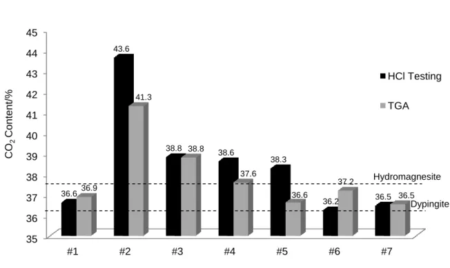
Thermogravimetric analysis and HCl acid digestion, explained further in Section 2. The results obtained by these methods are presented and compared in Fig. 7. The CO2 content of all the HMCs varied between
36.5-41.3% by TG whereas that of HCl acid testing was 36.2-43.6%. The results obtained from HCl acid testing were slightly higher than those from the TG for most of the carbonates, possibly due to the high volatility of the acid and the heat emitted as a result of the rigorous reaction taking place between the HMCs and HCl acid. However, there was in general a good correlation between the results obtained by the two methods.
The highest CO2 content was demonstrated by HMC#2 and 3, possibly contributing to the occurrence of the
exothermic peak discussed in Section 3.3. Considering that the theoretical CO2 content of dypingite and
hydromagnesite is 36.3% and 37.6%, respectively, those of HMCs #4 and 6 obtained by thermal analysis are very close to that of hydromagnesite, whereas HMCs #1, 5, and 7 contained a similar CO2 content to dypingite.
The rest of the HMCs could not be clearly grouped under each one of the two categories since their CO2
contents varied to an extent.
Fig. 7 CO2 contents of HMCs measured by TG and dissolving in HCl acid
4. Conclusions 35 36 37 38 39 40 41 42 43 44 45 #1 #2 #3 #4 #5 #6 #7 36.6 43.6 38.8 38.6 38.3 36.2 36.5 36.9 41.3 38.8 37.6 36.6 37.2 36.5 CO 2 C onte nt/ %
Hydrated Magnesium Carbonates
HCl Testing TGA
Dypingite Hydromagnesite
16
The investigation into the microstructure and thermal decomposition characteristics of seven different
commercially produced HMCs provided an insight into their chemical composition and thermal decomposition patterns involving the dehydration, dehydroxylation, and decarbonation steps. The distinction between heavy and light HMCs were outlined with respect to the results obtained from TG/DTA, SEM, XRD, and HCl acid analyses. The possibility of varying decomposition patterns and chemical compositions were explored in detail, with a discussion on the reasoning behind the occurrence of the exothermic peak. Some of the key findings of this study can be listed as:
1. The two groups of HMCs, characterized as light and heavy, show differences in microstructure. Heavy HMCs present a relatively impenetrable structure, while light HMCs are more porous due to the more widely dispersed arrangement of particles.
2. The three steps involving the removal of water of crystallization, decomposition of brucite to MgO, and decomposition of MgCO3 to MgO, indicated by distinct endothermic peaks on the DTA curve, do not
necessarily follow the decomposition pattern and the temperature ranges stated in the literature. The temperatures at which each reaction takes place differ for heavy and light HMCs.
3. TG results demonstrate that the chemical compositions of the studied HMCs do not exactly fit into the fixed stoichiometry of the known HMCs in the MgO-CO2-H2O system. The certain level of variation amongst the
compositions of HMCs highlighted that other compounds with varying water or carbon dioxide contents may exist in addition to the ones mentioned in literature.
4. The exothermic peak at ~520˚C was only apparent after the thermal decomposition of heavy HMCs, while it did not occur for the light HMCs. This was linked with the higher CO2 contents of the former, along with the
relatively delayed start of the decarbonation process, both placing a strain on the crystal lattice.
Further work aimed at studying the effects of the heating rate, sample size, and atmospheric conditions on the decomposition of these carbonates can be performed to provide a more comprehensive understanding of the decomposition process. Additional analytical techniques such as FTIR spectroscopy can be utilized with TG/DTA to identify and eliminate any uncertainty over the unfamiliar phases observed during thermal analysis, and understand the microstructural and structural changes that take place during the formation and
transformation of each compound within the MgO-CO2-H2O system to the fullest extent.
17
1. Rogner H-H, Zhou D, Bradley R, Crabbé P, Edenhofer O, Hare B et al. Introduction. Cambridge, United Kingdom and New York, NY, USA: Cambridge University Press, 2007.
2. Lackner KS. Carbonate chemistry for sequestering fossil carbon. Annual Review of Energy and the Environment. 2002;27:193–232.
3. Gerdemann SJ, Dahlin DC, O’Connor WK, Penner LR. Carbon dioxide sequestration by aqueous mineral carbonation of magnesium silicate minerals. Albany, OR, 97321: Albany Research Center, 2003.
4. O’Connor WK, Dahlin DC, Rush GE, Dahlin CL, Collins WK. Carbon dioxide sequestration by direct mineral carbonation: process mineralogy of feed and products. Minerals and Metallurgical Processing. 2002;19:95–101.
5. Hales MC, Frost RL, Martens WN. Thermo-Raman spectroscopy of synthetic nesquehonite - implication for the geosequestration of greenhouse gases. Journal of Raman Spectroscopy. 2008;39:1141–9.
6. Botha A, Strydom CA. Preparation of a magnesium hydroxy carbonate from magnesium hydroxide. Hydrometallurgy. 2001;62:175-83.
7. Khan N, Dollimore D, Alexander K, Wilburn FW. The origin of the exothermic peak in the thermal decomposition of basic magnesium carbonate. Thermochimica Acta. 2001;367-368:321-33.
8. Dell RM, Weller SW. The thermal decomposition of nesquehonite MgCO3·H2O and magnesium ammonium
carbonate MgCO3·(NH4)2CO3·4H2O. Transactions of the Faraday Society. 1959;55:2203-20.
9. Raade G. Dypingite, a new hydrous basic carbonate of magnesium, from Norway. The American Mineralogist. 1970;55(9-10):1457–65.
10. Holand W, Heide K. Untersuchung des einflusses der analysenbedingungen auf die zersetzung von 4MgCO3.Mg(OH)2.4H2O und die bildung von magnesit MgCO3. Thermochimica Acta. 1976;15:287-94.
11. Sawada Y, Yamaguchi J, Sakurai O, Uematsu K, Mizutani N, Kato M. Thermal decomposition of basic magnesium carbonates under high-pressure gas atmoshpheres. Thermochimica acta. 1979;32(1-2):277-91. 12. Sawada Y, Uematsu K, Mizutani N, Kato M. Thermal decomposition of hydromagnesite 4MgCO3 -
Mg(OH)2 - 4H2O under different partial pressures of carbon dioxide. Thermochimica acta. 1978;27(1-3):45-59.
doi:10.1016/0040-6031(78)85020-5.
13. Gennardo AR. The Science and Practice of Pharmacy. 17 ed. Remington's Pharmaceutical Sciences. Easton, PA: Mack Publishing Company; 1985.
14. Canterford JH, Tsambourakis G, Lambert B. Some observations on the properties of dypingite, Mg5(CO3)4(OH)2·5H2O, and related minerals. Mineralogical Magazine. 1984;48:437-42.
15. Davies PJ, Bubela B. The transformation of nesquehonite into hydromagnesite. Chemical Geology. 1973;12:289-300.
16. Königsberger E, Königsberger L-C, Gamsjäger H. Low-temperature thermodynamic model for the system Na2CO3-MgCO3-CaCO3-H2O. Geochimica et Cosmochimica Acta. 1999;63(19/20):3105-19.
17. Langmuir D. Stability of carbonates in the system MgO-CO2-H2O. Journal of Geology. 1965;73:730-54.
18. Power IM, Wilson SA, Thom JA, Dipple GM, Southam G. Biologically induced mineralization of dypingite by cyanobacteria from an alkaline wetland near Atlin, British, Columbia, Canada. Geochemical Transactions. 2007;8(13):1-16.
19. Sayles FL, Fyfe WS. The crystallization of magnesite from aqueous solution. Geochimica et Cosmochimica Acta. 1973;37:87-99.
20. Xiong Y, Lord AS. Experimental investigations of the reaction path in the MgO-CO2-H2O system in
solutions with various ionic strengths, and their applications to nuclear waste isolation. Applied Geochemistry. 2008;23:1634-59.
21. Lanas J, Alvarez JI. Dolomitic lime: thermal decomposition of nesquehonite. Thermochimica Acta 2004;421:123-32.
22. Ming DW, Franklin WT. Synthesis of lansfordite and nesquehonite. Soil Science Society of America Journal. 1985;49:1303-8.
23. Mansour SA. Study of thermal stabilization for polystyrene/carbon nanocomposites via TG/DSC techniques. Journal of Thermal Analysis and Calorimetry. 2013;112:579–83.
24. Vágvölgyi V, Frost RL, Hales M, Locke A, Kristóf J, Horváth E. Controlled rate thermal analysis of hydromagnesite. Journal of Thermal Analysis and Calorimetry. 2008;92(3):893–7.
25. Wu J-Y, Lee J-C, Wu Y-T, Wu S-H. Thermal analyses of four adsorption materials for environmental pollution by DSC and TG. Journal of Thermal Analysis and Calorimetry. 2013;112:665–70.
26. Harmathy T. Determining the temperature history of concrete constructions following fire exposure. Journal of the American Concrete Institute. 1968;65(11):959-64.
27. Giammar DE, Jr.R.G. B, Peters CA. Forsterite dissolution and magnesite precipitation at conditions relevant for deep saline aquifer storage and sequestration of carbon dioxide. Chemical Geology. 2005;217:257-76. 28. Ferrini V, De Vito C, Mignardi S. Synthesis of nesquehonite by reaction of gaseous CO2 with Mg chloride
solution: Its potential role in the sequestration of carbon dioxide. Journal of hazardous materials. 2009;168(2-3):832-7.
18
29. Teir S, S. E, C.-J. F, Zevenhoven R. Carbonation of minerals and industrial by-products for CO2
sequestration. 3rd International Green Energy Conference; Sweden, 2007.
30. Botha A, Strydom CA. DTA and FT-IR analysis of the rehydration of basic magnesium carbonate. Journal of Thermal Analysis and Calorimetry. 2003;71:987-95.
31. Choudhary VR, Pataskar SG, Gunjikar VG, Zope GB. Influence of preparation conditions of basic magnesium carbonate on its thermal analysis. Thermochimica Acta. 1994;232:95-110.
32. Sawada Y, Yamaguchi J, Sakurai O, Uematsu K, Mizutani N, Kato M. Thermogravimetric study on the decomposition of hydromagnesite 4MgCO3·Mg(OH)2·4H2O. Thermochimica acta. 1979;33(0):127-40.
doi:10.1016/0040-6031(79)87036-7.
33. Sawada Y, Yamaguchi J, Sakurai O, Uematsu K, Mizutani N, Kato M. Isothermal differential scanning calorimetry on an exothermic phenomenon during thermal decomposition of hydromagnesite 4MgCO3.Mg(OH)2.4H2O. Thermochimica Acta. 1979;34:233-7.
34. Montoya C, Lanas J, Arandigoyen M, Navarro I, Garcia Casado PJ, Alvarez JI. Study of ancient dolomitic mortars of the church of Santa Maria de Zamarce in Navarra (Spain): comparison with simulated standards. Thermochimica Acta. 2003;398:107–22.
35. Liska M. Properties and applications of reactive magnesia cements in porous blocks. Cambridge, UK: Department of Engineering, University of Cambridge, 2009.
36. Unluer C. Enhancing the carbonation of reactive magnesia cement-based porous blocks. Cambridge, UK: University of Cambridge, 2012.
37. Yanat'yeva OK, Rassonskaya IS. Metastable equilibria and solid phases in the CaCO3-MgCO3-H2O system.
Russian Journal of Inorganic Chemistry. 1961;6(6):730-3.
38. Kazakov AV, Tikhomirova MM, Plotnikova VI. The system of carbonate equilibria. International Geology Review. 1959;1(10):1-39.


![Fig. 4 XRD patterns of magnesium compounds in the MgO-CO 2 -H 2 O system [35]](https://thumb-eu.123doks.com/thumbv2/123doknet/14242042.486938/10.892.125.767.90.1114/fig-xrd-patterns-magnesium-compounds-mgo-h-o.webp)